Difference between revisions of "SJ One Board"
(→FreeRTOS Sample Project) |
|||
| Line 386: | Line 386: | ||
<BR/> | <BR/> | ||
| − | == FreeRTOS | + | == FreeRTOS Usage == |
=== Add a Task === | === Add a Task === | ||
<syntaxhighlight lang="cpp"> | <syntaxhighlight lang="cpp"> | ||
| Line 420: | Line 420: | ||
<BR/> | <BR/> | ||
| − | |||
=== Add a Terminal Command === | === Add a Terminal Command === | ||
<syntaxhighlight lang="cpp"> | <syntaxhighlight lang="cpp"> | ||
| Line 456: | Line 455: | ||
output.printf("ERROR for my command\n"); | output.printf("ERROR for my command\n"); | ||
} | } | ||
| + | } | ||
| + | </syntaxhighlight> | ||
| + | |||
| + | <BR/> | ||
| + | === printf() === | ||
| + | The <code>printf()</code> function is interrupt driven if you use FreeRTOS sample project, so you will find that the data is "queued" to be printed rather than be printed immediately. This can be a hassle during debugging because your data may not even print by the time your program crashes. You can, however, print data immediately at the expense of using the CPU cycles. | ||
| + | |||
| + | <syntaxhighlight lang="cpp"> | ||
| + | #include "printf_lib.h" | ||
| + | |||
| + | void freertos_print_immediately(void) | ||
| + | { | ||
| + | u0_dbg_printf("This will print immediately rather than queuing data to be printed later.\n"); | ||
} | } | ||
</syntaxhighlight> | </syntaxhighlight> | ||
Revision as of 23:03, 27 November 2013
Contents
Introduction
This article provides details of the SJ-One Board used by San Jose State University.
Obtain the Board
- If you are a San Jose State University student, you can obtain the board from SCE at Engr294.
- For remote users, you can contact Preet
About the Board
- LPC1758 User Manual
- File:2012SJOneBoardSchematic.pdf
- 512K ROM, 64K RAM, 1M SPI Flash, and Micro-SD for storage.
- Built-in Nordic Wireless (Board-to-Board communication)
- 4 Switches and 4 LEDs (both hard-wired)
- Sensors :
- Temperature, 3-Axis Acceleration, IR (remote control), and Light
- 2-Digit 7-Segment Display
- RTC Crystal with Backup Battery
- Socket for Xbee or Wifi Module (Uart2 or Uart3)
- Many GPIOs with two SPI, Multiple UARTs, and I2C availability
- Power from USB or External Power
Programming the Board
There are three ways to program the board:
- Use Hyperload; the instructions are documented here.
- **Write the programming binary file on SPI Flash or SD Card named "prog.bin"
- Hold the Button 1 & 2 on the board, and press RESET
- **Write the programming binary file on SPI Flash or SD Card
- Use example at "prog_handlers.cpp" or terminal command to flash from this file.
 ** Note about flashing from a file
  * This will only work with updated bootloader (boards shipped after Oct. 2013)
  * You can update the bootloader using FlashMagic
  * The *.bin file should be created as part of your project build/compilation
Board Block Diagrams
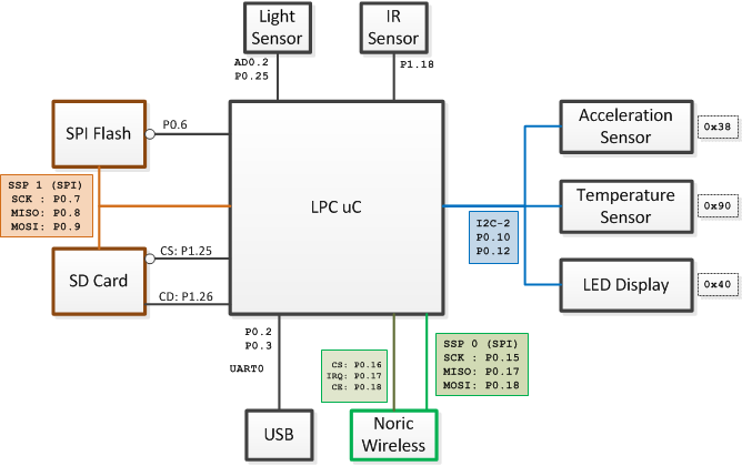
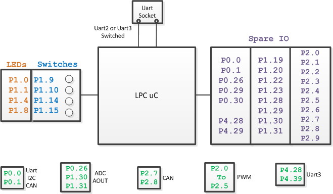
The block diagrams below show the connectivity to various different chips on the PCB, and also show which GPIOs are available to you. The first diagram shows the pins used for on-board sensors or interfaces. The second diagram shows IOs you can use.
Board Connections
Board IO
Board Overlay
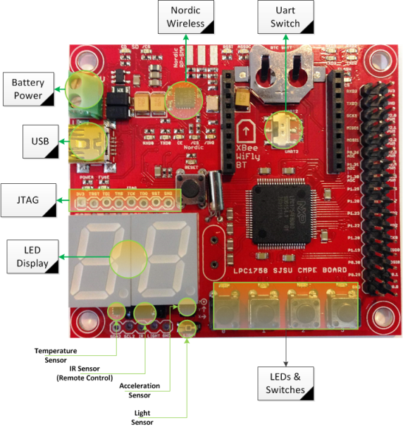
This board overlay can be compared against diagrams above to get an idea of where the IOs are located.
External SPI Devices
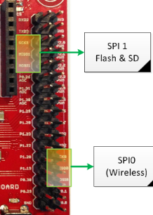
To hook up your external SPI device(s), use SPI#1 connections because there is already a driver in SJ-One sample project for this SPI. See the connections below and the sample code:
#include "spi1.h"

void access_my_spi_device()
{
   // Send 0xDEAD over to SPI device and get 2 bytes back:
   chip_select_my_device(true);
   {
       char byte_0 = spi1_exchange_byte(0xDE);
       char byte_1 = spi1_exchange_byte(0xAD);
   }
   chip_select_my_device(false);

   /**
    * You can use any GPIO for CS (chip-select) signal.
    * This example assumes CS is done through a function:
    *   chip_select_my_device(bool);
    */
} |
External I2C Devices
|
I2C#2 is tied to on-board sensors and you should utilize I2C 2's connection to hook up external I2C devices. See the connections below and the sample code: #include "I2C2.hpp"
void send_byte_to_my_i2c_device()
{
const char my_dev_addr = 0xBA; // Your device address
const char my_dev_reg = 0x01; // Write to 1st register of your device
const char my_dev_data = 0xAB; // Write 0xAB to reg 0x01
I2C2::getInstance().writeReg(my_dev_addr, my_dev_reg, my_dev_data);
} |
External Components
GPIO & High-Power LED
To connect a high-power LED, you will need the help of an external component because the CPU cannot provide enough power on its own. The easiest way is to design a circuit using an N-MOSFET, which is easily available in the market for less than $1 per module. Please click on this demonstration link, and wire-up the GATE, SOURCE, and DRAIN as demonstrated. More details are at this article.
int main(void)
{
    /* Assume we attached our P1.20 to the MOSFETs GATE pin
     * You can use any pin defined at gpio.hpp file and locate that pin
     * on your board. Use "Ctrl+Shift+R" and search for "gpio.hpp" file.
     */
    GPIO pin20(P1_20);   /* Use P1.20 as General Purpose Input/Output (GPIO) */
    pin20.setAsOutput(); /* Use this pin as OUTPUT */

    pin20.setHigh(); /* Turn on voltage to 3.3v */
    pin20.setLow();  /* Turn off voltage to 0v  */
}
Maxbotics EZ Ultrasonic Sensor
See this article for more details.
Buzzer
A buzzer needs a PWM to operate, or you can operate it using a GPIO but it can waste your CPU cycles. Before you start with the code, attach a GPIO or PWM pin to a 1K resistor leading to the buzzer's red wire. The black wire should be connected to ground.
#include "gpio.hpp"
#include "utilities.h"

int main(void)
{
    /* Assume we attached our P1.20 to the buzzer */
    GPIO buzzer(P1_20);   /* Use P1.20 as General Purpose Input/Output (GPIO) */
    buzzer.setAsOutput(); /* Use this pin as OUTPUT */

    while (1) {
        /* Beep for one second */
        for (int i = 0; i < 1000; i+=2) {
            delay_ms(1);
            buzzer.setHigh();
            delay_ms(1);
            buzzer.setLow();
        }
    }

    /* 2nd option: Use a PWM */
}
Motion Sensor
A typical motion sensor like a PIR motion sensor is very easy to attach. Power-up the sensor using 5v, and connect the ground. Then take a resistor, tie one end to 5v, and the other end to the motion's signal. Finally, tie the signal to one of your GPIOs.
#include "gpio.hpp"
#include "utilities.h"

int main(void)
{
    /* Assume we attached our P1.20 to out motion sensor's output pin */
    GPIO motion(P1_20);   /* Use P1.20 as General Purpose Input/Output (GPIO) */
    motion.setAsInput();
    motion.enablePullUp();

    while(1) {
        /* Get average of one second */
        int count = 0;
        for (int i = 0; i < 1000; i++) {
            /* If output is low, then motion has been detected, but it could be false positive */
            if (!motion.read()) {
                count++;
            }
            delay_ms(1);
        }

        /* Test and calibrate yourself: */
        bool motionDetected = (count > 50);
    }
}
Board Sample Code & Experiments
ADC Input
#include “adc0.h”

void adc_read(void)
{
    /*********************************************************
     * ADC is already initialized before main() is called.
     * There are 3 ADC pins labeled on the SJ-One board.
     * You can use one or more channels as illustrated below.
     */

    LPC_PINCON->PINSEL1 |= (1 << 20); // ADC-3 is on P0.26, select this as ADC0.3
    LPC_PINCON->PINSEL3 |= (3 << 28); // ADC-4 is on P1.30, select this as ADC0.4
    LPC_PINCON->PINSEL3 |= (3 << 30); // ADC-5 is on P1.31, select this as ADC0.5

    int adc3 = adc0_get_reading(3); // Read the value of ADC-3
    int adc4 = adc0_get_reading(4); // Read the value of ADC-4
    int adc5 = adc0_get_reading(5); // Read the value of ADC-5
}
File I/O
You can read or write files on the SPI Flash or an SD card. You can open a limited amount of files using standard C libraries. First, at your sys_config.h file, please enable ENABLE_C_FILE_IO
#include "io.hpp"

void file_io()
{
    /* Option 1 : C library I/O (less efficient)
     * 0: is for SPI Flash
     * 1: is for SD Card
     */
    FILE *fd = fopen("0:myfile.txt", "r");
    char line[128] = { 0 };
    if (fd) {
        fgets(line, sizeof(line)-1, fd);
        fclose(fd);
    }


    /* Option 2 : Use "storage" object (more efficient)
     * This option doesn't require 'ENABLE_C_FILE_IO'
     */

    /* Write "hello" to "myfile.txt" */
    Storage::write("0:myfile.txt", "hello", 5, 0))

    /* Read the size of data array from myfile.txt
     * Not using 0: or 1: will default to 0: (SPI Flash)
     */
    char data[16] = { 0 };
    Storage::read("myfile.txt", data, sizeof(data)-1, 0));

    /* Option 3 : Directly use ff.h API that will
     * read/write SD card or SPI Flash
     * Read documentation at : http://elm-chan.org/fsw/ff/00index_e.html
     */
}
LEDs, Switches & LED Display
There are on-board switches and LEDs you may use. Furthermore, you can interface your board to external LEDs or switches as well.
#include "io.hpp"

void led_sw()
{
    if (SW.getSwitch(1)) { /* Check if button 1 is pressed */
        LE.on(1);          /* Turn on LED # 1              */
        LD.setNumber(1);   /* LED display will show "1"    */
    }
    else {
        LE.setAll(0); /* Turn off all LEDs */
        LD.clear();   /* Clear the display */
    }
}
Motor & Servo Control
See the sample code below, and reference this article for more details.
/* Read this include file for more info */
#include "lpc_pwm.hpp"

/**
 * You can control up to 6 servos with hardware signals (and more with sw)
 * Each signal is mapped to from P2.0 to P2.5
 */
void motor_control()
{
    /* Use 1Khz PWM.  Each PWM shares the 1st frequency you set */
    PWM motor1(PWM::pwm1, 1000);
    PWM motor2(PWM::pwm2, 0);

    /* Set to 50% motor speed */
    motor1.set(50);
    motor2.set(50);
}
void servo_control()
{
    /* Use 50Hz PWM for servos.  Each PWM will be 50Hz */
    PWM servo1(PWM::pwm1, 50);
    PWM servo2(PWM::pwm2, 0);

    servo1.set(5.0);  ///< Set to left position
    servo2.set(10.0); ///< Set to right position
}
Sensors
This section provides examples of how to read data values from the sensors.
#include "io.hpp"

void sensors()
{
    int light_value = LS.getRawValue();

    int tilt_x = AS.getX();
    int tilt_y = AS.getY();
    int tilt_z = AS.getZ();

    int temperature_f = TS.getFarenheit();
}
Timer Services
Getting system time using C libraries should work, but you can also get time directly from "rtc.h". Other than this, there are two more timer services you can use as demonstrated in the code sample below.
#include "lpc_sys.h"
#include "soft_timer.hpp"

void timers()
{
    /* You can get the time since the board has been powered in milli-seconds */
    uint64_t uptime_ms = sys_get_uptime_ms();

    /* You can compute time delta in microseconds too */
    uint64_t timer_micro_sec = sys_get_high_res_timer_us();
    delay_ms(100);
    uint64_t delta = sys_get_high_res_timer_us() - timer_micro_sec;

    /* There is also a polling timer available in C++
     * Read "soft_timer.hpp" for more info.
     */
    SoftTimer myTimer(1000);
    if (myTimer.expired()) {
        /* Do something */
    }
}
Uart Socket
You can install BT, Xbee, or RN-XV (Wifi) onto the black socket on the board. The pins can either be routed to UART2 or UART3 using a tiny switch in the middle of the socket. Once the wireless module is installed, you can use the following code to interact with it.
#include "uart2.hpp"
#include "uart3.hpp"

void uart()
{
    Uart2& u2 = Uart2::getInstance();
    Uart3& u3 = Uart3::getInstance();

    u2.init(38400); /* Init baud rate */
    u3.init(19200); /* Init baud rate */

    u2.putline("Hello World\n");
    u3.putline("Hello World\n");

    /* Reference the documentation of Uart2 or Uart3 header file for more functions.
     * Most of the functionality is in a base class called uart_dev.cpp
     */
}
Wireless
This board can communicate to other boards using a very low-powered wireless technology. Here are various resources :
- Code samples are at Interactive Wireless Nodes Project (towards the bottom).
- You can read about Doxygen generated docs or read through wireless.h
- VIDEO : Mesh Network API
FreeRTOS Usage
Add a Task
/* Add this on top of main()
 * Read "scheduler.task" for more documentation
 * Read "examples.cpp" for more examples.
 */
class myTask : public scheduler_task
{
    public:
        myTask (uint8_t priority) : scheduler_task("mytask", 512*8, priority) {
        }

        /* this function will be called in a loop by FreeRTOS */
        bool run(void *p)
        {
            puts("Hello");
            vTaskDelay(1000);
            return true; /* Returning false will suspend the task */
        }
};

int main(void)
{
   // ...
   /* Add your new task here */
   scheduler_add_task(new myTask(PRIORITY_LOW));
   // ...
   scheduler_start(false);
   // ...
}
Add a Terminal Command
/* At terminal.cpp, add the following code at the taskEntry() function */
bool terminalTask::taskEntry()
{
    // ...

    CMD_HANDLER_FUNC(myCmdHandler);
    cp.addHandler(myCmdHandler,   "newcmd",  "This is help message. 'newcmd test' will display: 'OK'");

    // ...
    return true;
}


/* ----------------------------------------------
 * Your source file, such as "my_source.cpp"
 * We will add our command handler function here
 */
#include "command_handler.hpp"

CMD_HANDLER_FUNC(myCmdHandler)
{
    /* cmdParams is a str passed to you after user's command, ie: "newcmd test"
     * output is a UartDev base class that you can use to output a reply message
     * See "handlers.cpp" for more examples
     */
    if(cmdParams == "test") {
        output.printf("OK!\n");
    }
    else {
        output.printf("ERROR for my command\n");
    }
}
printf()
The printf() function is interrupt driven if you use FreeRTOS sample project, so you will find that the data is "queued" to be printed rather than be printed immediately. This can be a hassle during debugging because your data may not even print by the time your program crashes. You can, however, print data immediately at the expense of using the CPU cycles.
#include "printf_lib.h"

void freertos_print_immediately(void)
{
    u0_dbg_printf("This will print immediately rather than queuing data to be printed later.\n");
}
Add Source Code
C++ File
Adding C++ code is simple. Simply add your *.hpp and *.cpp files and you are good to go! The file extensions must be *.hpp or *.cpp
C File
Adding C source code is a bit more hassle since compiling with mixed C/C++ requires some extra headers, so please use the following code as template for your header file. The *.c file doesn't require any extra stuff though.
#ifndef MY_NEW_FILE_H__
#define MY_NEW_FILE_H__

/* need the C++ header */
#ifdef __cplusplus
extern "C"
#endif


/* Now include your function headers */


#ifdef __cplusplus
}
#endif
#endif /* end MY_NEW_FILE_H__ */


