Simple Embedded System Project
Contents
Objective
Work together as a group to create an LED lighting system. You will create hardware that controls power to a 12v LED light (or LED strip), and then write the software to control the LED light.
Think outside the box; you can do much more :
- You can create an alarm clock and turn on LEDs on/off
- Orientation or rotation can turn on/off lights or change colors.
- You can combine your group with another group to make your project look better!
Note that your board contains wireless mesh network allowing you to freely connect many boards together and they can all communicate with each other. This can be useful if you wish to earn extra credit by interacting with multiple boards. For example, a motion sensor on one board can turn on the lights on multiple boards. The API is documented at your board's wikipedia page.
Tools Needed
- Wire wrapping tool - https://www.youtube.com/watch?v=8SSOKppwpAE
- Wire wrapping wire - http://www.adafruit.com/product/1446
- LED strip
- 12 V Power Supply
- SJOne Board(s)
- Resistors
- MOSFET
Connecting the MOSFET
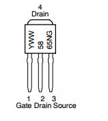
Read the datasheet for the MOSFET - http://www.mouser.com/ds/2/308/on%20semiconductor_ntd5865n-d-327059.pdf
Also, Please click on this demonstration link, and wire-up the GATE, SOURCE, and DRAIN as demonstrated. More details are at this article
LED Strip
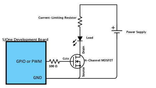
Current limiting resistors as shown in circuit may not be needed if using LED strip instead of single LED. LED strip usually has 2 wires: one for supply (12V) and the other for ground. If you have an RGB LED strip, it will have 4 wires Power supply, Red, Green and Blue. All the Red, Green and Blue are Grounds. Ground the color that you want to use: example: Ground RED to turn on LED strip as RED. Ground all the three colors to get white.
Do NOT use strips that are longer than a meter. cut them to required length before using.
LED strips: http://www.adafruit.com/search?q=LED+strip&b=1
Power Supply
Purchase a 12V/2A adaptor. Cut the power cord at a suitable length to reveal Power and ground lines. Use wire wrapping to connect these lines to the circuit.
Alternate way: Purchase this (http://www.adafruit.com/product/368) component and use wires to connect to the + and - terminals .
Connections
The connections for an LED, MOSFET, board and power supply are shown below:

All connections can be made using the wire wrapping tool. A video describing wire wrapping procedure is given above under the Tools needed section.
Electronic Parts Companies and Useful Engineering Resources
Using the SJOne Board and connecting external components
http://www.socialledge.com/sjsu/index.php?title=SJ_One_Board
This page also has a section for using wireless communication between multiple SJOne boards. In order to use the wireless functionality, an SMA connector needs to be soldered on the board. An antenna can be attached to the SMA connector.
Structure
For simplicity, the minimum requirement is that a team of three is able to have control for an LED strip. It has to be interactive, for example: turning on the LEDs upon light sensor or another trigger.
Requirements
Technical
Your grade will depend on how well you follow the following requirements :
- You must use a
switch / casecode section in your code. - You must use a state machine in at least one of your nodes.
- This could be as simple as a state machine for "Manual Lights" vs. "Automatic Lights"
- All functions used shall be no larger than 50 lines of code.
- Split into smaller sub-functions.
- You must utilize functions that use pass-by-value and pass-by-reference.
- Project should be self-contained
- Project should be enclosed, with no wires visible.
- Project should not require the Hercules Terminal to operate.
- Project should preferably operate with its own independent power source (or battery pack).
- All buttons should be labeled.
- An operator should be able to operate without reading an instruction manual.
Items to Submit
At the end of the project, the following items need to be submitted :
- Full source-code of all the projects
- Individual evaluations about team members and their contribution
- This will be confidential, and you can submit as one per person (at Canvas).
Project Report
You must submit a full, documented report for your project (one per group of six). The following are minimum sections required in your PDF submitted report:
- Introduction
- What does your project do?
- Try to sell your project in this section.
- Add a sub-section called "Features & Communication Table"
- List the features of each node and the communication table.
- At least four unique features per node should be listed.
- Schematics
- List the hardware you used.
- Use "LibreOffice Draw" to draw the schematics
- Implementation
- Show your software workings using a flow-chart
- Use bullets and pictures to show the "how" part.
- Show what Software you used to control your Hardware.
- Testing
- What kind of tests did you perform?
- What kind of problems did you solve?
- Conclusion
- What did you learn?
- What worked, and what didn't work?
- How would you improve your project?
Challenges & Hints
Challenges
Over the course of the project, you will encounter some real-world problems such as :
- How will you design your project to be user friendly?
- How will you collaborate in your team?
- How will you balance your budget and keep parts cost to a minimum?
- How will you make your project more creative? How will it stand out?
