Difference between revisions of "S24: Team Gran Turismo"
(→Project Title) |
(→Hardware Design) |
||
| (75 intermediate revisions by the same user not shown) | |||
| Line 1: | Line 1: | ||
== Project Title == | == Project Title == | ||
| + | |||
<b>Gran Turismo</b> | <b>Gran Turismo</b> | ||
| + | |||
<HR> | <HR> | ||
| − | + | [[File:IMG 4302.jpg]] | |
| − | |||
| − | |||
| − | |||
| − | |||
| − | |||
| − | |||
| − | |||
== Abstract == | == Abstract == | ||
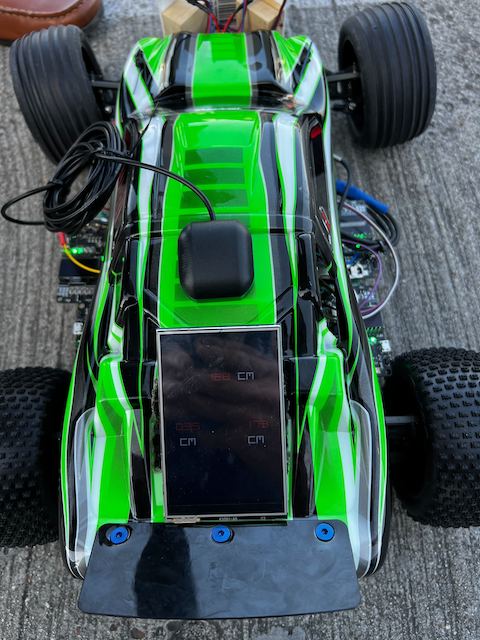
| − | + | "The Gran Turismo" is an autonomous RC car designed to navigate to a specified destination using GPS coordinates, communicated via a mobile application. The car integrates four microcontrollers (Driver, Sensor/Bridge, Geo, and Motor nodes) which communicate over a Controller Area Network (CAN) bus. It utilizes FreeRTOS to manage periodic tasks for data gathering, processing, and decision-making, ensuring effective obstacle detection and avoidance while maintaining the intended path. | |
=== Introduction === | === Introduction === | ||
| − | The project was divided into | + | The project was divided into 5 modules: |
| − | * Sensor | + | * Sensor/Bridge node |
| − | * Motor | + | * Motor node |
| − | * | + | * Geo node |
| − | * Android | + | * Driver node |
| + | * Android App | ||
=== Team Members & Responsibilities === | === Team Members & Responsibilities === | ||
| − | + | [[File:IMG 4285.jpg]] | |
| − | + | Team Members: | |
<BR/> | <BR/> | ||
| − | < | + | Daniel Zhao Yeung <BR/> |
| − | < | + | Suryanto Phienanda <BR/> |
| + | Kaijian Wu <BR/> | ||
| + | Lianshi Gan <BR/> | ||
| − | |||
| − | |||
| − | |||
| − | + | Gitlab Project Link - [https://gitlab.com/lianshi.gan/sjtwo-c-team-gran-turismo C243_GT] | |
| − | + | <BR/> | |
| − | |||
| − | * | + | {| class="wikitable" |
| − | ** | + | |- |
| − | ** | + | ! scope="col"| Team Members |
| + | ! scope="col"| Task Responsibility | ||
| + | |- | ||
| + | ! scope="row" style="text-align: left;"| | ||
| + | * Daniel Zhao Yeung | ||
| + | | | ||
| + | * Geo Node | ||
| + | |- | ||
| + | ! scope="row" style="text-align: left;"| | ||
| + | * [https://www.linkedin.com/in/lianshi-gan-967494116/ Lianshi Gan] | ||
| + | | | ||
| + | * Sensor Node | ||
| + | |- | ||
| + | ! scope="row" style="text-align: left;"| | ||
| + | * Suryanto Phienanda | ||
| + | | | ||
| + | * Motor Node | ||
| + | |- | ||
| + | ! scope="row" style="text-align: left;"| | ||
| + | * Suryanto Phienanda | ||
| + | | | ||
| + | * Driver Node | ||
| + | |- | ||
| + | ! scope="row" style="text-align: left;"| | ||
| + | * Kaijian Wu | ||
| + | | | ||
| + | * Mobile App, Bridge Node | ||
| + | |- | ||
| − | + | |} | |
| − | |||
| − | |||
| − | |||
| − | |||
| − | |||
| − | |||
| − | |||
| − | |||
| − | |||
| − | |||
<HR> | <HR> | ||
<BR/> | <BR/> | ||
| + | |||
== Schedule == | == Schedule == | ||
| Line 77: | Line 89: | ||
* Connect db9 to Busmaster. | * Connect db9 to Busmaster. | ||
* Assign tasks to each team member. | * Assign tasks to each team member. | ||
| − | | <font color = " | + | | <font color = "green">Completed |
|- | |- | ||
| Line 87: | Line 99: | ||
* Get all the sensors and parts. | * Get all the sensors and parts. | ||
* Play with sensors and SJ2 boards. | * Play with sensors and SJ2 boards. | ||
| − | | <font color = " | + | | <font color = "green">Completed |
|- | |- | ||
| Line 98: | Line 110: | ||
* Get Data from different modules(GPS, Sensors). | * Get Data from different modules(GPS, Sensors). | ||
* Starting to check on motor. | * Starting to check on motor. | ||
| − | | <font color = " | + | | <font color = "green">Completed |
|- | |- | ||
| Line 107: | Line 119: | ||
* Develop LCD module. | * Develop LCD module. | ||
* Start working on driver module. | * Start working on driver module. | ||
| − | * | + | * Build libraries for all modules (Bluetooth/WIFI, GPS, Sensor....). |
| − | |||
| − | |||
| − | |||
* Continue work on mobile app. | * Continue work on mobile app. | ||
| − | | <font color = " | + | | <font color = "green">Completed |
|- | |- | ||
| Line 123: | Line 132: | ||
* Create unit/integration tests. | * Create unit/integration tests. | ||
* Continue work on mobile app. | * Continue work on mobile app. | ||
| − | | <font color = " | + | | <font color = "green">Completed |
|- | |- | ||
| Line 133: | Line 142: | ||
* Motors with PID control. | * Motors with PID control. | ||
* Continue work on mobile app. | * Continue work on mobile app. | ||
| − | | <font color = " | + | | <font color = "green">Completed |
|- | |- | ||
| Line 143: | Line 152: | ||
* Integrate bluetooth module | * Integrate bluetooth module | ||
* Continue with mobile app | * Continue with mobile app | ||
| − | | <font color = " | + | | <font color = "green">Completed |
|- | |- | ||
| Line 152: | Line 161: | ||
* Finalize/Connect mobile app with RC car. | * Finalize/Connect mobile app with RC car. | ||
* Obstacle avoidance. | * Obstacle avoidance. | ||
| − | | <font color = " | + | | <font color = "green">Completed |
|- | |- | ||
| Line 161: | Line 170: | ||
* PROTOTYPE 3 | * PROTOTYPE 3 | ||
* Prepare for outdoor tests. | * Prepare for outdoor tests. | ||
| − | | <font color = " | + | | <font color = "green">Completed |
|- | |- | ||
| Line 170: | Line 179: | ||
* PROTOTYPE 4 | * PROTOTYPE 4 | ||
* Perform outdoors tests and recalibrate. | * Perform outdoors tests and recalibrate. | ||
| − | | <font color = " | + | | <font color = "green">Completed |
|- | |- | ||
| Line 178: | Line 187: | ||
| | | | ||
* Final Demo | * Final Demo | ||
| − | | <font color = " | + | | <font color = "green">Completed |
|} | |} | ||
| Line 205: | Line 214: | ||
| 8 | | 8 | ||
| Free Samples | | Free Samples | ||
| + | |- | ||
| + | ! scope="row"| 3 | ||
| + | | Ultrasonic Sensor URM09 from DFRobots | ||
| + | | dfrobot [https://www.dfrobot.com/product-1862.html] | ||
| + | | 4 | ||
| + | | $8 * 4 | ||
| + | |- | ||
| + | ! scope="row"| 4 | ||
| + | | DSD TECH HM-10 Bluetooth 4.0 BLE | ||
| + | | Amazon [https://www.amazon.com/dp/B06WGZB2N4?psc=1&ref=ppx_yo2ov_dt_b_product_details] | ||
| + | | 1 | ||
| + | | $12.00 | ||
| + | |- | ||
| + | ! scope="row"| 5 | ||
| + | | Tilt Compensated Magnetic Compass (CMPS14) | ||
| + | | RobotShop [https://www.robotshop.com/products/tilt-compensated-magnetic-compass-cmps14] | ||
| + | | 1 | ||
| + | | $41 | ||
| + | |- | ||
| + | ! scope="row"| 6 | ||
| + | | GT-U7 GPS Module GPS Receiver | ||
| + | | Amazon [https://www.amazon.com/Navigation-Satellite-Compatible-Microcontroller-Geekstory/dp/B07PRGBLX7?th=1] | ||
| + | | 1 | ||
| + | | $15 | ||
| + | |- | ||
| + | ! scope="row"| 7 | ||
| + | | Bingfu Waterproof Active GPS Navigation Antenna | ||
| + | | Amazon [https://www.amazon.com/gp/product/B083D59N55/ref=ppx_yo_dt_b_search_asin_title?ie=UTF8&th=1] | ||
| + | | 1 | ||
| + | | $41 | ||
|- | |- | ||
|} | |} | ||
| Line 210: | Line 249: | ||
<HR> | <HR> | ||
<BR/> | <BR/> | ||
| + | |||
== Printed Circuit Board == | == Printed Circuit Board == | ||
<Picture and information, including links to your PCB> | <Picture and information, including links to your PCB> | ||
| Line 221: | Line 261: | ||
=== Hardware Design === | === Hardware Design === | ||
<Show your CAN bus hardware design> | <Show your CAN bus hardware design> | ||
| + | |||
| + | |||
=== DBC File === | === DBC File === | ||
| − | + | [[DBC file]https://gitlab.com/lianshi.gan/sjtwo-c-team-gran-turismo/-/blob/GT_infrastructure/dbc/project.dbc?ref_type=heads] | |
| − | < | + | |
| + | <pre> | ||
| + | BO_ 100 DRIVER_CMD: 3 DRIVER | ||
| + | SG_ DRIVER_CMD_heartbeat : 0|1@1+ (1,0) [0|0] "" SENSOR,MOTOR | ||
| + | SG_ DRIVER_CMD_steer : 1|4@1+ (1,-5) [-5|5] "degrees" MOTOR | ||
| + | SG_ MOTOR_CMD_drive : 5|4@1+ (1,-2) [-2|5] "kph" MOTOR | ||
| + | |||
| + | BO_ 105 GPS_CURRENT_COORD : 8 GPS | ||
| + | SG_ GPS_CURRENT_COORD_lat_degree : 0|8@1- (1,-90) [-90|90] "degrees" BRIDGE | ||
| + | SG_ GPS_CURRENT_COORD_lat_minutes : 8|6@1+ (1,0) [0|60] "minutes" BRIDGE | ||
| + | SG_ GPS_CURRENT_COORD_lat_seconds : 14|16@1+ (0.001,0) [0|60] "seconds" BRIDGE | ||
| + | SG_ GPS_CURRENT_COORD_long_degree : 30|9@1- (1,-180) [-180|180] "degrees" BRIDGE | ||
| + | SG_ GPS_CURRENT_COORD_long_minutes : 39|6@1+ (1,0) [0|60] "minutes" BRIDGE | ||
| + | SG_ GPS_CURRENT_COORD_long_seconds : 45|16@1+ (0.001,0) [0|60] "seconds" BRIDGE | ||
| + | |||
| + | BO_ 110 GPS_DESTINATION_LOCATION: 8 BRIDGE | ||
| + | SG_ GPS_DESTINATION_LOCATION_lat_degree : 0|8@1- (1,-90) [-90|90] "degrees" GPS | ||
| + | SG_ GPS_DESTINATION_LOCATION_lat_minutes : 8|6@1+ (1,0) [0|60] "minutes" GPS | ||
| + | SG_ GPS_DESTINATION_LOCATION_lat_seconds : 14|16@1+ (0.001,0) [0|60] "seconds" GPS | ||
| + | SG_ GPS_DESTINATION_LOCATION_long_degree : 30|9@1- (1,-180) [-180|180] "degrees" GPS | ||
| + | SG_ GPS_DESTINATION_LOCATION_long_minutes : 39|6@1+ (1,0) [0|60] "minutes" GPS | ||
| + | SG_ GPS_DESTINATION_LOCATION_long_seconds : 45|16@1+ (0.001,0) [0|60] "seconds" GPS | ||
| + | |||
| + | BO_ 120 COMPASS_CURRENT: 7 COMPASS | ||
| + | SG_ COMPASS_CURRENT_heading : 0|12@1+ (1,0) [0|359.9] "degrees" DRIVER | ||
| + | SG_ COMPASS_CURRENT_bearing : 12|12@1+ (1,0) [0|359.9] "degrees" DRIVER | ||
| + | SG_ COMPASS_CURRENT_distance_to_dest : 24|32@1+ (0.1,0) [0|0] "meters" DRIVER | ||
| + | BO_ 200 SENSOR_SONARS: 8 SENSOR | ||
| + | SG_ SENSOR_SONARS_front_left : 0|13@1+ (0.1,0) [0|520] "cm" DRIVER | ||
| + | SG_ SENSOR_SONARS_front_right : 13|13@1+ (0.1,0) [0|520] "cm" DRIVER | ||
| + | SG_ SENSOR_SONARS_front_middle : 26|13@1+ (0.1,0) [0|520] "cm" DRIVER | ||
| + | SG_ SENSOR_SONARS_rear : 39|13@1+ (0.1,0) [0|520] "cm" DRIVER | ||
| + | BO_ 300 MOTOR_CMD: 2 MOTOR | ||
| + | SG_ MOTOR_CMD_speed_kph : 0|8@1+ (1,0) [0|35] "kph" DEBUG | ||
| + | SG_ MOTOR_CMD_angle : 8|8@1+ (1,0) [-5|5] "degrees" DEBUG | ||
| + | |||
| + | </pre> | ||
<HR> | <HR> | ||
<BR/> | <BR/> | ||
| − | == Sensor ECU == | + | |
| − | + | == Sensor and Bridge ECU == | |
| + | [https://gitlab.com/lianshi.gan/sjtwo-c-team-gran-turismo/-/merge_requests/2 Sensor Gitlab] | ||
=== Hardware Design === | === Hardware Design === | ||
| + | [[File:20240516 173629.jpg]] | ||
| + | |||
| + | <HR> | ||
| + | Connection Diagram | ||
| + | [[File:sensor hw.png]] | ||
| + | |||
| + | ==== Ultrasonic Sensor ==== | ||
| + | |||
| + | [[File:MFG SEN0388.jpeg|200px]] | ||
| + | |||
| + | Selecting the appropriate distance sensor is crucial for the success of the project. Our team chose the Ultrasonic Sensor URM09 from DFRobots due to its ease of use and cost-effectiveness. The URM09 offers multiple communication protocols, and we opted for the I2C package to simplify the configuration and reading process, allowing us to focus on the overall system integration. | ||
| + | |||
| + | * Ultra-Sonic Sensor URM09 (I2C Protocol) | ||
| + | ** '''Supply Voltage:''' 3.3~5.5V DC | ||
| + | ** '''Operating Current:''' 20mA | ||
| + | ** '''Operating Temperature Range:''' -10℃~+70℃ | ||
| + | ** '''Measurement Range:''' 2cm~500cm (can be set) | ||
| + | ** '''Resolution:''' 1cm | ||
| + | ** '''Accuracy:''' 1% | ||
| + | ** '''Frequency:''' 50Hz Max | ||
| + | ** '''Dimension:''' 47mm × 22 mm/1.85” × 0.87” | ||
| + | |||
| + | ==== Bluetooth Module ==== | ||
| + | For the communication between the Mobile app and the RC car. We use the DSD TECH HM-10 Bluetooth 4.0 BLE module. This module communicate with the SJ2 board by using UART. It transmits raw data between mobile app and bridge. It is lightweight and has small size. | ||
| + | |||
| + | [[File:DSD TECH HM-10 Bluetooth 4.0 BLE.jpg|200px]] | ||
| + | |||
| + | |||
| + | * DSD TECH HM-10 Bluetooth 4.0 BLE | ||
| + | ** '''Operating voltage:''' 3.3V | ||
| + | ** '''Core module:''' MH-10 | ||
| + | ** '''Support device:''' iOS device(iphone and ipad). But does not support the version is lower than the android 4.3 phone(it don't support classic bluetooth 2.0 spp features) | ||
=== Software Design === | === Software Design === | ||
| − | < | + | Preiocally tasks |
| + | * receiving data | ||
| + | ** Current coordinate from Geo ECU (Geo node) | ||
| + | ** Destination coordinates, command data from Mobile App (App) | ||
| + | ** Sensor data from sensor (Ultrasonic Sensor URM09) | ||
| + | * sending data: | ||
| + | ** Destination coordinates, sensor data to Driver ECU (Driver node) | ||
| + | ** Sensor data to app (App) | ||
| + | |||
| + | |||
| + | <pre> | ||
| + | void periodic_callbacks__1Hz(uint32_t callback_count) { | ||
| + | if (can__is_bus_off(can1)) { | ||
| + | can__reset_bus(can1); | ||
| + | gpio__toggle(board_io__get_led0()); | ||
| + | } | ||
| + | can_bus_handler__receive_current_gps(); | ||
| + | can_bus_handler_service_mia_1Hz(); | ||
| + | const dbc_GPS_CURRENT_COORD_s current_coord = can_bus_handler__get_received_current_gps(); | ||
| + | |||
| + | bluetooth__send_current_gps_to_app(current_coord); | ||
| + | bluetooth__send_sensor_data_to_app(); | ||
| + | } | ||
| + | |||
| + | void periodic_callbacks__10Hz(uint32_t callback_count) { | ||
| + | bluetooth__receive_all_data_from_app(); | ||
| + | |||
| + | can_bus_handler__transmit_sensors(); | ||
| + | can_bus_handler__transmit_command(); | ||
| + | can_bus_handler__transmit_destination_gps(); | ||
| + | } | ||
| + | </pre> | ||
| + | |||
=== Technical Challenges === | === Technical Challenges === | ||
| − | < | + | ==== Bluetooth Module ==== |
| + | *''' Challenge:''' : Due to its design, it can read/send a string up to 20 characters at a time. Any string more than 20 characters will be break into 2 lines automatically and process. The datasheet provides limited information when developing the Bluetooth module. | ||
| + | *''' Solution:''' On SJ2 board side, we break out data into serval strings and pad '0' into some data string to ensure it is send in exact 20 characters. | ||
| + | |||
| + | ==== Sensor Module ==== | ||
| + | ===== Transmitting Sensor Data ===== | ||
| + | Since there are some "printf" were set up for debugging sensor data, we transmitting data on 5Hz in order to avoid crashing the SJ2 board. It wasn't any issue when we doing unit testing and obstacle avoiding testing run. However, the low 5 Hz cause turning delay when we actually run the RC car in high speed. Remember to ensure sensor data transmitting at least 10 to 20 Hz. | ||
| + | |||
| + | <pre> | ||
| + | void periodic_callbacks__10Hz(uint32_t callback_count) { | ||
| + | bluetooth__receive_all_data_from_app(); | ||
| + | |||
| + | |||
| + | can_bus_handler__transmit_sensors(); | ||
| + | |||
| + | can_bus_handler__transmit_command(); | ||
| + | can_bus_handler__transmit_destination_gps(); | ||
| + | } | ||
| + | </pre> | ||
| + | |||
| + | ===== Configure 4 ADC channels ===== | ||
| + | We load the distance sensor data by ADC channel. | ||
| + | There are only 3 channels ready to use on SJ2 board. | ||
| + | Need to modify P0_26 as below to unlock ADC: | ||
| + | |||
| + | <pre> | ||
| + | static void distance__configure_all_adc_pins(void) { | ||
| + | LPC_IOCON->P0_25 &= ~(3 << 3); | ||
| + | LPC_IOCON->P0_25 &= ~(1 << 7); | ||
| + | |||
| + | LPC_IOCON->P0_26 &= ~(3 << 3); | ||
| + | LPC_IOCON->P0_26 &= ~(1 << 16); | ||
| + | LPC_IOCON->P0_26 &= ~(1 << 7); | ||
| + | |||
| + | LPC_IOCON->P1_30 &= ~(3 << 3); | ||
| + | LPC_IOCON->P1_30 &= ~(1 << 7); | ||
| + | |||
| + | LPC_IOCON->P1_31 &= ~(3 << 3); | ||
| + | LPC_IOCON->P1_31 &= ~(1 << 7); | ||
| + | } | ||
| + | </pre> | ||
<HR> | <HR> | ||
<BR/> | <BR/> | ||
| + | |||
== Motor ECU == | == Motor ECU == | ||
<Picture and link to Gitlab> | <Picture and link to Gitlab> | ||
| Line 259: | Line 443: | ||
== Geographical Controller == | == Geographical Controller == | ||
| − | + | [https://gitlab.com/lianshi.gan/sjtwo-c-team-gran-turismo/-/merge_requests/4 Geo Gitlab] | |
=== Hardware Design === | === Hardware Design === | ||
| + | ====Tilt Compensated Magnetic Compass (CMPS14)==== | ||
| + | [[File:Cmps14.png]] | ||
| + | * Features a 3-axis gyro and 3-axis magnetometer | ||
| + | * Offers equally impressive performance to the CMPS12 | ||
| + | * Allows the calibration to be stopped and instead rely on a static calibration profile | ||
| + | The CMPS14 Tilt Compensated Magnetic Compass is equipped with a three-axis magnetometer, gyroscope, and accelerometer. It uses the advanced BNO080 to run algorithms that correct for any errors caused by the PCB tilting. Additionally, the module offers the option to halt calibration and use a static calibration profile instead. | ||
| + | |||
| + | |||
| + | ====Bingfu Waterproof Active GPS Navigation Antenna==== | ||
| + | [[File:Bingfu_antenna.png|200px]] | ||
| + | |||
| + | * Antenna: Radio | ||
| + | * Brand: BINGFU | ||
| + | * Color with U.FL Cable | ||
| + | * Impedance: 50 Ohm | ||
| + | * Maximum Range: 3 Meters | ||
| + | |||
| + | The Bingfu Waterproof Active GPS Navigation Antenna is a durable, water-resistant antenna with an adhesive mount and an SMA male connection. It comes with a 6-inch coaxial cable that connects from U.FL IPX IPEX to an SMA female connector. This antenna is designed for use with GPS modules and receivers to enhance tracking capabilities. | ||
| + | |||
| + | |||
| + | ====GT-U7 GPS Module GPS Receiver==== | ||
| + | [[File:Gt-u7.png|200px]] | ||
| + | |||
| + | * Brand: Geekstory | ||
| + | * Map Type: Satellite | ||
| + | *Item Weight: 0.2 Ounces | ||
| + | |||
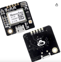
| + | The GT-U7 is a compact GPS module with low power usage and high sensitivity. It uses a 7th generation chip and is compatible with NEO-6M software. This module excels in difficult environments like urban canyons and dense forests, providing precise location tracking. It includes a USB interface for easy connection to a computer using a standard phone cable, and comes with an active antenna. | ||
=== Software Design === | === Software Design === | ||
| − | + | ||
| + | Periodic callbacks are scheduled at 10 Hz. | ||
| + | |||
| + | void periodic_callbacks__10Hz(uint32_t callback_count) { | ||
| + | can_bus_handler__handle_all_messages(); | ||
| + | can_bus_handler__transmit_gps(); | ||
| + | can_bus_handler__transmit_compass(); | ||
| + | } | ||
| + | |||
| + | |||
| + | Preiocally tasks | ||
| + | * receiving data | ||
| + | ** Heading from compass (cmps14) | ||
| + | ** Destination coordinates from Mobile App | ||
| + | ** Current coordinates from GPS receiver (gt-u7) | ||
| + | * sending data: | ||
| + | ** Current coordinates to mobile app | ||
| + | ** Distance and bearing (from calculation of current and destination coordinates) to driver controller | ||
| + | ** Heading (from cmps14) to driver controller | ||
=== Technical Challenges === | === Technical Challenges === | ||
| − | + | * Getting accurate data of compass | |
| + | ** Follow the calibration procedure in the CMPS14 user manual. | ||
| + | ** Avoid areas with excessive wiring or magnets nearby. | ||
| + | ** Use the LED on the SJ2 board to indicate the calibration level. | ||
| + | ** Only transfer data when the `readyBit` is greater than 0. | ||
<HR> | <HR> | ||
<BR/> | <BR/> | ||
| − | + | == Communication LCD == | |
| − | |||
| − | == Communication | ||
<Picture and link to Gitlab> | <Picture and link to Gitlab> | ||
| Line 289: | Line 521: | ||
<HR> | <HR> | ||
<BR/> | <BR/> | ||
| − | == | + | |
| + | == Driver Module == | ||
<Picture and link to Gitlab> | <Picture and link to Gitlab> | ||
=== Hardware Design === | === Hardware Design === | ||
| + | [[File:IMG 4314.jpg]] | ||
| + | [[File:IMG 4309.jpg]] | ||
| + | [[File:IMG 4311.jpg]] | ||
| + | [[File:IMG 4312.jpg]] | ||
=== Software Design === | === Software Design === | ||
| Line 304: | Line 541: | ||
<HR> | <HR> | ||
<BR/> | <BR/> | ||
| + | |||
== Mobile Application == | == Mobile Application == | ||
| − | + | [https://github.com/kwu5/243_s2024_gran_turismo_app Github Mobile link] | |
| + | |||
| + | === Software Design === | ||
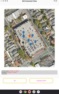
| + | We develop an Android React Native app on with the support from Expo. The app is responsible for receiving the current GPS location of the RC car, as well as the sensor data from the SJ2 board for debug purpose. The app also send command with the destination data to the the Bridge to tell the RC car where to go. | ||
| + | |||
| + | [[File: mobileapp.jpg|200px]] | ||
| + | |||
| + | ==== Feature ==== | ||
| + | * Current destination location, check point locations are marked on the map. | ||
| + | * Sensor data are also shown in the app. | ||
| + | * Click on the map to mark a location and press 'GO' will send out the command and destination to the car. After data is send, the button title will change to "STOP". "Emergency STOP" button is also provided. | ||
| − | |||
| − | + | The command data sent from the app is either "GO!!" or "STOP". In the "GO!!" case, the app also render the destination data that the user mark on the app to the Bridge. Example of data sent will be "GO!!","LAT:37.720681","LONG: -122.422832","STOP". | |
| − | |||
=== Technical Challenges === | === Technical Challenges === | ||
| − | + | *''' Challenge:''' We are facing a issue that when the data is sent from the bridge in 10Hz or 5Hz, the app will stop responding after running for a certain time. | |
| − | + | *''' Solution:''' We move the bridge data transmitting function so it is called in 1Hz instead. | |
<BR/> | <BR/> | ||
| Line 321: | Line 567: | ||
<HR> | <HR> | ||
<BR/> | <BR/> | ||
| + | |||
== Conclusion == | == Conclusion == | ||
<Organized summary of the project> | <Organized summary of the project> | ||
Latest revision as of 06:27, 24 May 2024
Contents
Project Title
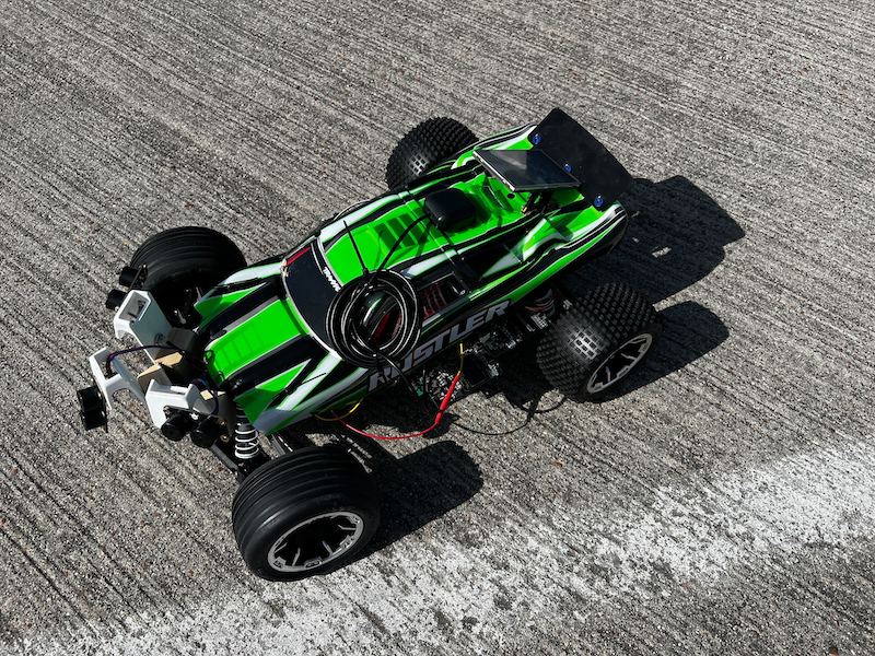
Gran Turismo
Abstract
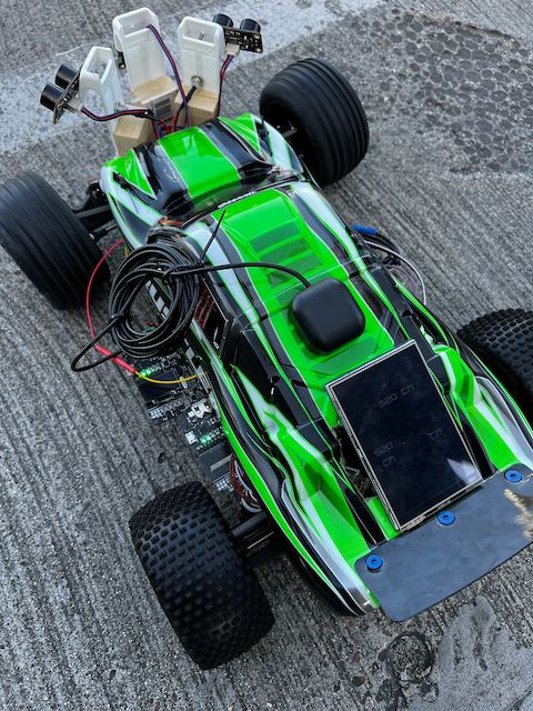
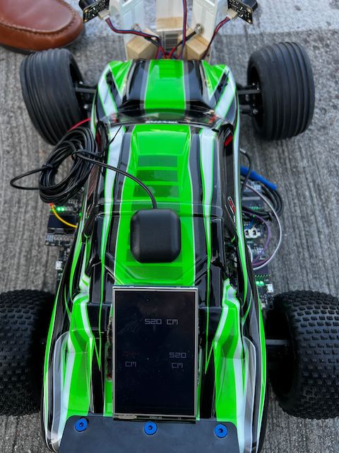
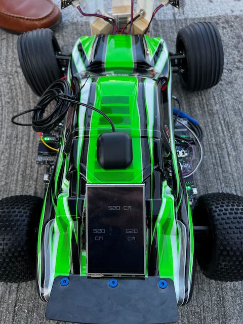
"The Gran Turismo" is an autonomous RC car designed to navigate to a specified destination using GPS coordinates, communicated via a mobile application. The car integrates four microcontrollers (Driver, Sensor/Bridge, Geo, and Motor nodes) which communicate over a Controller Area Network (CAN) bus. It utilizes FreeRTOS to manage periodic tasks for data gathering, processing, and decision-making, ensuring effective obstacle detection and avoidance while maintaining the intended path.
Introduction
The project was divided into 5 modules:
- Sensor/Bridge node
- Motor node
- Geo node
- Driver node
- Android App
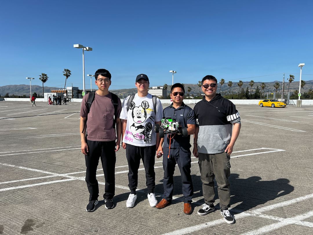
Team Members & Responsibilities
Team Members:
Daniel Zhao Yeung
Suryanto Phienanda
Kaijian Wu
Lianshi Gan
Gitlab Project Link - C243_GT
| Team Members | Task Responsibility |
|---|---|
|
|
| |
|
|
|
|
|
|
Schedule
| Week# | Start Date | End Date | Task | Status |
|---|---|---|---|---|
| 1 | 03/04/2024 | 03/10/2024 |
|
Completed |
| 2 | 03/11/2024 | 03/17/2024 |
|
Completed |
| 3 | 03/18/2024 | 03/24/2024 |
|
Completed |
| 4 | 03/25/2024 | 03/31/2024 |
|
Completed |
| 5 | 04/01/2024 | 04/07/2024 |
|
Completed |
| 6 | 04/08/2024 | 04/14/2024 |
|
Completed |
| 7 | 04/15/2024 | 04/21/2024 |
|
Completed |
| 8 | 04/22/2024 | 04/28/2024 |
|
Completed |
| 9 | 04/29/2024 | 05/05/2024 |
|
Completed |
| 10 | 05/06/2024 | 05/12/2024 |
|
Completed |
| 11 | 05/13/2024 | 05/19/2024 |
|
Completed |
Parts List & Cost
| Item# | Part Desciption | Vendor | Qty | Cost |
|---|---|---|---|---|
| 1 | RC Car | Traxxas | 1 | $250.00 |
| 2 | CAN Transceivers MCP2551-I/P | Microchip [1] | 8 | Free Samples |
| 3 | Ultrasonic Sensor URM09 from DFRobots | dfrobot [2] | 4 | $8 * 4 |
| 4 | DSD TECH HM-10 Bluetooth 4.0 BLE | Amazon [3] | 1 | $12.00 |
| 5 | Tilt Compensated Magnetic Compass (CMPS14) | RobotShop [4] | 1 | $41 |
| 6 | GT-U7 GPS Module GPS Receiver | Amazon [5] | 1 | $15 |
| 7 | Bingfu Waterproof Active GPS Navigation Antenna | Amazon [6] | 1 | $41 |
Printed Circuit Board
<Picture and information, including links to your PCB>
CAN Communication
<Talk about your message IDs or communication strategy, such as periodic transmission, MIA management etc.>
Hardware Design
<Show your CAN bus hardware design>
DBC File
BO_ 100 DRIVER_CMD: 3 DRIVER
 SG_ DRIVER_CMD_heartbeat : 0|1@1+ (1,0) [0|0] "" SENSOR,MOTOR
 SG_ DRIVER_CMD_steer : 1|4@1+ (1,-5) [-5|5] "degrees" MOTOR
 SG_ MOTOR_CMD_drive : 5|4@1+ (1,-2) [-2|5] "kph" MOTOR

BO_ 105 GPS_CURRENT_COORD : 8 GPS
 SG_ GPS_CURRENT_COORD_lat_degree : 0|8@1- (1,-90) [-90|90] "degrees" BRIDGE
 SG_ GPS_CURRENT_COORD_lat_minutes : 8|6@1+ (1,0) [0|60] "minutes" BRIDGE
 SG_ GPS_CURRENT_COORD_lat_seconds : 14|16@1+ (0.001,0) [0|60] "seconds" BRIDGE
 SG_ GPS_CURRENT_COORD_long_degree : 30|9@1- (1,-180) [-180|180] "degrees" BRIDGE
 SG_ GPS_CURRENT_COORD_long_minutes : 39|6@1+ (1,0) [0|60] "minutes" BRIDGE
 SG_ GPS_CURRENT_COORD_long_seconds : 45|16@1+ (0.001,0) [0|60] "seconds" BRIDGE

BO_ 110 GPS_DESTINATION_LOCATION: 8 BRIDGE
 SG_ GPS_DESTINATION_LOCATION_lat_degree : 0|8@1- (1,-90) [-90|90] "degrees" GPS
 SG_ GPS_DESTINATION_LOCATION_lat_minutes : 8|6@1+ (1,0) [0|60] "minutes" GPS
 SG_ GPS_DESTINATION_LOCATION_lat_seconds : 14|16@1+ (0.001,0) [0|60] "seconds" GPS
 SG_ GPS_DESTINATION_LOCATION_long_degree : 30|9@1- (1,-180) [-180|180] "degrees" GPS
 SG_ GPS_DESTINATION_LOCATION_long_minutes : 39|6@1+ (1,0) [0|60] "minutes" GPS
 SG_ GPS_DESTINATION_LOCATION_long_seconds : 45|16@1+ (0.001,0) [0|60] "seconds" GPS

BO_ 120 COMPASS_CURRENT: 7 COMPASS
  SG_ COMPASS_CURRENT_heading : 0|12@1+ (1,0) [0|359.9] "degrees" DRIVER
  SG_ COMPASS_CURRENT_bearing : 12|12@1+ (1,0) [0|359.9] "degrees" DRIVER
  SG_ COMPASS_CURRENT_distance_to_dest : 24|32@1+ (0.1,0) [0|0] "meters" DRIVER

BO_ 200 SENSOR_SONARS: 8 SENSOR
 SG_ SENSOR_SONARS_front_left : 0|13@1+ (0.1,0) [0|520] "cm" DRIVER
 SG_ SENSOR_SONARS_front_right : 13|13@1+ (0.1,0) [0|520] "cm" DRIVER
 SG_ SENSOR_SONARS_front_middle : 26|13@1+ (0.1,0) [0|520] "cm" DRIVER
 SG_ SENSOR_SONARS_rear : 39|13@1+ (0.1,0) [0|520] "cm" DRIVER

BO_ 300 MOTOR_CMD: 2 MOTOR
 SG_ MOTOR_CMD_speed_kph : 0|8@1+ (1,0) [0|35] "kph" DEBUG
 SG_ MOTOR_CMD_angle : 8|8@1+ (1,0) [-5|5] "degrees" DEBUG
Sensor and Bridge ECU
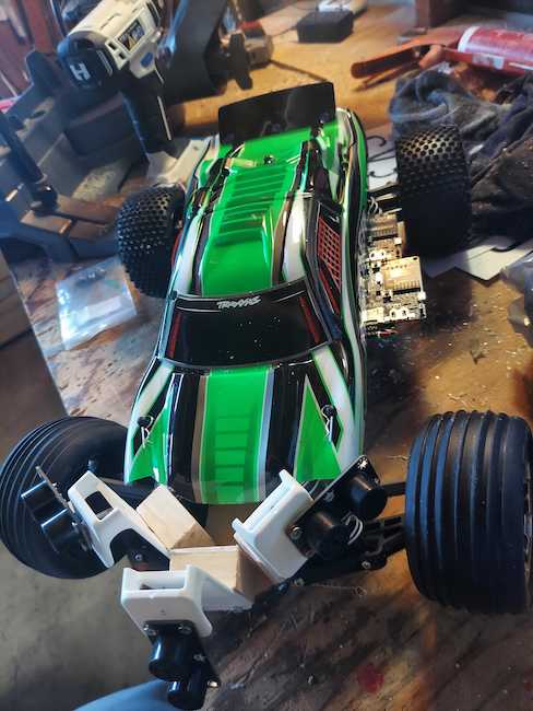
Hardware Design
Ultrasonic Sensor
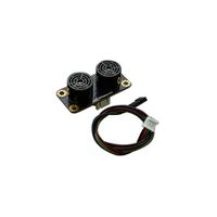
Selecting the appropriate distance sensor is crucial for the success of the project. Our team chose the Ultrasonic Sensor URM09 from DFRobots due to its ease of use and cost-effectiveness. The URM09 offers multiple communication protocols, and we opted for the I2C package to simplify the configuration and reading process, allowing us to focus on the overall system integration.
- Ultra-Sonic Sensor URM09 (I2C Protocol)
- Supply Voltage: 3.3~5.5V DC
- Operating Current: 20mA
- Operating Temperature Range: -10℃~+70℃
- Measurement Range: 2cm~500cm (can be set)
- Resolution: 1cm
- Accuracy: 1%
- Frequency: 50Hz Max
- Dimension: 47mm × 22 mm/1.85” × 0.87”
Bluetooth Module
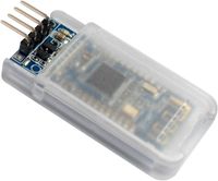
For the communication between the Mobile app and the RC car. We use the DSD TECH HM-10 Bluetooth 4.0 BLE module. This module communicate with the SJ2 board by using UART. It transmits raw data between mobile app and bridge. It is lightweight and has small size.
- DSD TECH HM-10 Bluetooth 4.0 BLE
- Operating voltage: 3.3V
- Core module: MH-10
- Support device: iOS device(iphone and ipad). But does not support the version is lower than the android 4.3 phone(it don't support classic bluetooth 2.0 spp features)
Software Design
Preiocally tasks
- receiving data
- Current coordinate from Geo ECU (Geo node)
- Destination coordinates, command data from Mobile App (App)
- Sensor data from sensor (Ultrasonic Sensor URM09)
- sending data:
- Destination coordinates, sensor data to Driver ECU (Driver node)
- Sensor data to app (App)
void periodic_callbacks__1Hz(uint32_t callback_count) {
  if (can__is_bus_off(can1)) {
    can__reset_bus(can1);
    gpio__toggle(board_io__get_led0());
  }
  can_bus_handler__receive_current_gps();
  can_bus_handler_service_mia_1Hz();
  const dbc_GPS_CURRENT_COORD_s current_coord = can_bus_handler__get_received_current_gps();

  bluetooth__send_current_gps_to_app(current_coord);
  bluetooth__send_sensor_data_to_app();
}

void periodic_callbacks__10Hz(uint32_t callback_count) {
  bluetooth__receive_all_data_from_app();

  can_bus_handler__transmit_sensors();
  can_bus_handler__transmit_command();
  can_bus_handler__transmit_destination_gps();
}
Technical Challenges
Bluetooth Module
- Challenge: : Due to its design, it can read/send a string up to 20 characters at a time. Any string more than 20 characters will be break into 2 lines automatically and process. The datasheet provides limited information when developing the Bluetooth module.
- Solution: On SJ2 board side, we break out data into serval strings and pad '0' into some data string to ensure it is send in exact 20 characters.
Sensor Module
Transmitting Sensor Data
Since there are some "printf" were set up for debugging sensor data, we transmitting data on 5Hz in order to avoid crashing the SJ2 board. It wasn't any issue when we doing unit testing and obstacle avoiding testing run. However, the low 5 Hz cause turning delay when we actually run the RC car in high speed. Remember to ensure sensor data transmitting at least 10 to 20 Hz.
void periodic_callbacks__10Hz(uint32_t callback_count) {
  bluetooth__receive_all_data_from_app();


  can_bus_handler__transmit_sensors();

  can_bus_handler__transmit_command();
  can_bus_handler__transmit_destination_gps();
}
Configure 4 ADC channels
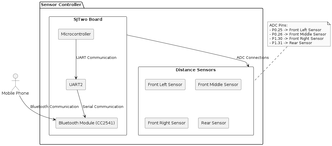
We load the distance sensor data by ADC channel. There are only 3 channels ready to use on SJ2 board. Need to modify P0_26 as below to unlock ADC:
static void distance__configure_all_adc_pins(void) {
  LPC_IOCON->P0_25 &= ~(3 << 3);
  LPC_IOCON->P0_25 &= ~(1 << 7);

  LPC_IOCON->P0_26 &= ~(3 << 3);
  LPC_IOCON->P0_26 &= ~(1 << 16);
  LPC_IOCON->P0_26 &= ~(1 << 7);

  LPC_IOCON->P1_30 &= ~(3 << 3);
  LPC_IOCON->P1_30 &= ~(1 << 7);

  LPC_IOCON->P1_31 &= ~(3 << 3);
  LPC_IOCON->P1_31 &= ~(1 << 7);
}
Motor ECU
<Picture and link to Gitlab>
Hardware Design
Software Design
<List the code modules that are being called periodically.>
Technical Challenges
< List of problems and their detailed resolutions>
Geographical Controller
Hardware Design
Tilt Compensated Magnetic Compass (CMPS14)
- Features a 3-axis gyro and 3-axis magnetometer
- Offers equally impressive performance to the CMPS12
- Allows the calibration to be stopped and instead rely on a static calibration profile
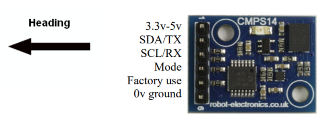
The CMPS14 Tilt Compensated Magnetic Compass is equipped with a three-axis magnetometer, gyroscope, and accelerometer. It uses the advanced BNO080 to run algorithms that correct for any errors caused by the PCB tilting. Additionally, the module offers the option to halt calibration and use a static calibration profile instead.
- Antenna: Radio
- Brand: BINGFU
- Color with U.FL Cable
- Impedance: 50 Ohm
- Maximum Range: 3 Meters
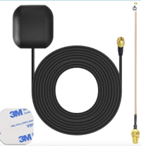
The Bingfu Waterproof Active GPS Navigation Antenna is a durable, water-resistant antenna with an adhesive mount and an SMA male connection. It comes with a 6-inch coaxial cable that connects from U.FL IPX IPEX to an SMA female connector. This antenna is designed for use with GPS modules and receivers to enhance tracking capabilities.
GT-U7 GPS Module GPS Receiver
- Brand: Geekstory
- Map Type: Satellite
- Item Weight: 0.2 Ounces
The GT-U7 is a compact GPS module with low power usage and high sensitivity. It uses a 7th generation chip and is compatible with NEO-6M software. This module excels in difficult environments like urban canyons and dense forests, providing precise location tracking. It includes a USB interface for easy connection to a computer using a standard phone cable, and comes with an active antenna.
Software Design
Periodic callbacks are scheduled at 10 Hz.
 void periodic_callbacks__10Hz(uint32_t callback_count) {
 can_bus_handler__handle_all_messages();
 can_bus_handler__transmit_gps();
 can_bus_handler__transmit_compass();
 }
Preiocally tasks
- receiving data
- Heading from compass (cmps14)
- Destination coordinates from Mobile App
- Current coordinates from GPS receiver (gt-u7)
- sending data:
- Current coordinates to mobile app
- Distance and bearing (from calculation of current and destination coordinates) to driver controller
- Heading (from cmps14) to driver controller
Technical Challenges
- Getting accurate data of compass
- Follow the calibration procedure in the CMPS14 user manual.
- Avoid areas with excessive wiring or magnets nearby.
- Use the LED on the SJ2 board to indicate the calibration level.
- Only transfer data when the `readyBit` is greater than 0.
Communication LCD
<Picture and link to Gitlab>
Hardware Design
Software Design
<List the code modules that are being called periodically.>
Technical Challenges
< List of problems and their detailed resolutions>
Driver Module
<Picture and link to Gitlab>
Hardware Design
Software Design
<List the code modules that are being called periodically.>
Technical Challenges
< List of problems and their detailed resolutions>
Mobile Application
Software Design
We develop an Android React Native app on with the support from Expo. The app is responsible for receiving the current GPS location of the RC car, as well as the sensor data from the SJ2 board for debug purpose. The app also send command with the destination data to the the Bridge to tell the RC car where to go.
Feature
- Current destination location, check point locations are marked on the map.
- Sensor data are also shown in the app.
- Click on the map to mark a location and press 'GO' will send out the command and destination to the car. After data is send, the button title will change to "STOP". "Emergency STOP" button is also provided.
The command data sent from the app is either "GO!!" or "STOP". In the "GO!!" case, the app also render the destination data that the user mark on the app to the Bridge. Example of data sent will be "GO!!","LAT:37.720681","LONG: -122.422832","STOP".
Technical Challenges
- Challenge: We are facing a issue that when the data is sent from the bridge in 10Hz or 5Hz, the app will stop responding after running for a certain time.
- Solution: We move the bridge data transmitting function so it is called in 1Hz instead.
Conclusion
<Organized summary of the project>
<What did you learn?>
Project Video
Project Source Code
Advise for Future Students
<Bullet points and discussion>
Acknowledgement
=== References ===
