Difference between revisions of "S18: Spark - MP3 Music Player with Audio Spectrum"
Proj user9 (talk | contribs) m (→Audio Analyzer) |
Proj user9 (talk | contribs) m (→Audio Analyzer) |
||
| Line 211: | Line 211: | ||
[[File:CMPE244_spark_freq_dec_Interface.png|thumb|500x250px|right|Interface between LED and SJOne Board]] | [[File:CMPE244_spark_freq_dec_Interface.png|thumb|500x250px|right|Interface between LED and SJOne Board]] | ||
| − | This | + | This analyser takes input from Audio decoder for left and right side music. SJOne outputs values of RS and ST pins and reads input data from S pin which is connected to ADC pin (P0.26) of SJOne. |
Audio Analyzer S pin -> SJOne P0.26 pin (ADC) | Audio Analyzer S pin -> SJOne P0.26 pin (ADC) | ||
Revision as of 19:21, 23 May 2018
Contents
- 1 Spark - MP3 Music Player with Audio Spectrum
- 2 Abstract
- 3 Objectives & Introduction
- 4 Schedule
- 5 Parts List & Cost
- 6 Design & Implementation
- 7 Testing & Technical Challenges
- 8 Conclusion
- 9 References
Spark - MP3 Music Player with Audio Spectrum
Abstract
The project aims to build an embedded system based music system using SJOne (LPC1758) board. The system will play music through a speaker interfaced with the board. A mobile application will be used to remotely control the system using Bluetooth. The app will be able to send the start and stop signal to play music as well as switch the song and modify volume. The playlist for music will be stored on an SD card mounted on the SJOne board. An audio decoder is required as a mediator between speaker and SJone board. It will read data from SD card using SPI interface, convert this data into audio data and send to the speaker. RGB Spectrum of Audio will be shown on the LED.
Objectives & Introduction
Show list of your objectives. This section includes the high level details of your project. You can write about the various sensors or peripherals you used to get your project completed.
Team Members & Responsibilities
- Sucheta Iyer
- Interfacing the SJONE board with speakers via the audio decoder
- Sneha Sharma
- Interfacing the SJONE board with speakers via the audio decoder
- Android application
- Krishna Sai Anirudh Katamreddy
- PCB design
- Ashwini Bhargava
- Interfacing the SJONE board with RGB Display
- Doyal Patel
- Interfacing the SJONE board with RGB Display
- Android application
Schedule
Show a simple table or figures that show your scheduled as planned before you started working on the project. Then in another table column, write down the actual schedule so that readers can see the planned vs. actual goals. The point of the schedule is for readers to assess how to pace themselves if they are doing a similar project.
| Week# | Date | Task | Actual |
|---|---|---|---|
| 1 | 4/3/2018 | Project Abstract | Completed |
| 2 | 4/17//2018 | Order Components (MP3 Decoder,16*32 LED Display) | Completed |
| 3 | 4/24//2018 | Initialize LED screen with different colors.
Read music data from SD card through SPI. |
Completed |
| 4 | 5/1/2018 | Initializing single LED and testing it with sample algorithm with different colors(completed)
Initialize the Audio Decoder through SPI communication and read manufacturer ID - (completed) Read from Sjone board and play sample song - (completed) Read from Memory card(SJone) and play sample song - (in progress) Designed a PCB which can hold MP3 player shield and two SJOne boards. Connected circuits between MP3 player shield and one SJOne, LED matrix and second SJOne board. Communicating SJOne with android application using bluetooth. |
Completed |
| 5 | 5/8/2018 | Get audio spectrum values and display on LED.
Pass the song data received through SD card to the audio decoder Listen to sample music on headphone/speaker. Added Audio Analyzer to the PCB design. Reviewed all the circuit connections and dimensions between components pins. Ordered the PCB. Developing user interface on android application. |
Completed |
| 6 | 5/15/2018 | Testing and Bug Fixing
Soldering the PCB. Final Report |
In Progress |
Parts List & Cost
| Sr. No. | Component | Cost |
|---|---|---|
| 1 | SJONE board | $80 |
| 2 | Audio Decoder | $24.95 |
| 3 | 16*32 RGB Screen | $32.42 |
| 4 | PCB | $80.00 |
| 4 | Total | $297.37 |
Design & Implementation
The design section can go over your hardware and software design. Organize this section using sub-sections that go over your design and implementation.
Hardware Design
Discuss your hardware design here. Show detailed schematics, and the interface here.
Audio Decoder
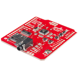
The Sparkfun MP3 Player Shield was used in this project. This includes the VS1053B MP3 audio decoder IC which decodes the supplied audio files. The audio decoder is capable of decoding audio data of various formats such as WAV, MP3, MIDI and AAC. Audio data in MP3 format is chosen for this project.
Input: MP3 audio file transmitted through SPI
Output: Audio to the headphone jack and header pins.
Bluetooth Module and Android App
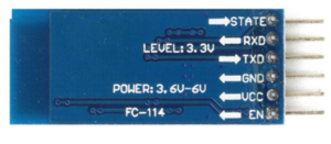
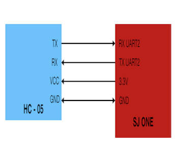
The Bluetooth Module connects with the SJOne Board via UART and the data received is transmitted via Bluetooth to the SparkMusicPlayer Android App. Similarly, data sent via Bluetooth by the App is communicated via UART to the SJOne board. The entire flow is displayed below.
1. Bluetooth Module
The HC-05 Bluetooth module is used in this project. This module is capable of serial communication with the microcontroller over UART and is capable of sending and receiving information via Bluetooth from paired devices.
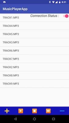
2. SparkMusicPlayer Android App
Native Android app that connects with HC-05 module (and thereby to the SJOne Board) via Bluetooth.
Data Received by the App: A list of songs available on the SD Card mounted on the SJOne board.
Data Transmitted by the App: Control signals - Play, Pause, Stop, Volume Up/Down and Song Selection from the received list of songs.
The screen of the Android app is as shown below.
Frequency Decoder
The frequency decoder module uses the MSGEQ7 graphic equalizer display IC to split the music into 7 frequency bands. The 7 frequency bands are: 63Hz, 160Hz, 400Hz, 1kHz, 2.5kHz, 6.25kHz and 16kHz. The peak level of each band is detected and multiplexed to the output to provide a DC representation. The strobe and reset pins are used to select the DC peak output. Reset high resets the multiplexor. Reset low enables the strobe pin. At the leading edge of the first strobe, the first frequency band 63Hz is on the output. On each additional leading edge strobe the next frequency band(160Hz, 400Hz, 1kHz, 2.5kHz, 6.25kHz, 16kHz) is detected.
LED Matrix
Text
Text
Text
Text
Text
PCB Design
PCB is being used to connect Sparkfun MP3 player shield, LED Matrix and Audio Analyzer with two SJOne boards.
Hardware Interface
In this section, you can describe how your hardware communicates, such as which BUSes used. You can discuss your driver implementation here, such that the Software Design section is isolated to talk about high level workings rather than inner working of your project.
Audio Decoder
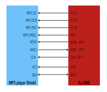
The Audio Decoder breakout board communicates with the SJOne board over SPI and is interfaced with the SPI-1 pins of the SJOne board as follows:
Clock Pin (Pin 13) - SJOne SPI-1 Clock Pin
MISO Pin (Pin 12) - SJOne SPI-1 MISO Pin
MOSI Pin (Pin 11) - SJOne SPI-1 MOSI Pin
MP3 CS: This is the Chip Select Pin for the audio decoder which is to be activated while sending control signals.
MP3 DCS: This is the Chip Select Pin for the audio decoder which is to be activated while sending audio data signals.
MP3 RST: This is the Reset pin for the audio decoder.
MP3 DREQ: This is the Data Request Pin through which the audio decoder signals that it is ready to accept another 32 bytes of audio data.
VCC pin - SJOne 3.3V pin
GND pin - SJOne GND Pin
Bluetooth and Android App
The HC-05 Bluetooth module is used in this project. It communicates with the SJOne board over UART and is interfaced with the UART2 pins of the SJOne board as follows:
HC-05 RX pin - SJOne UART2 TX pin
HC-05 TX pin - SJOne UART2 RX pin
VCC pin - SJOne 3.3V pin
GND pin - SJOne GND Pin
Audio Analyzer
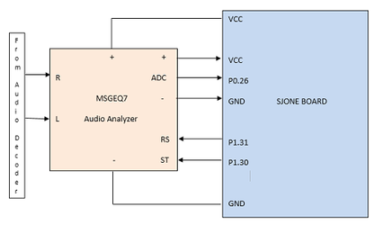
This analyser takes input from Audio decoder for left and right side music. SJOne outputs values of RS and ST pins and reads input data from S pin which is connected to ADC pin (P0.26) of SJOne.
   Audio Analyzer S pin  -> SJOne P0.26 pin (ADC)
   Audio Analyzer RS pin   -> SJOne P1.31 pin
   Audio Analyzer ST pin   -> SJOne P1.30 pin
   Audio Analyzer + pin    -> SJOne VCC pin
   Audio Analyzer - pin    -> SJOne GND pin
LED Matrix
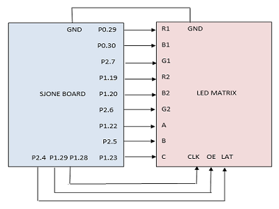
To display frequency spectrum of music input adafruit’s 16 x 32 LED Matrix is used. It is interfacing with LPC1758 using multiple GPIO pins. The LED matrix is connected to LPC1758 board by connecting three select pins to select rows (A, B and C), selection of colors using (R1,B1,R2,B2,G1,G2), Clock (clk), OE (Output enable), and Latency (LAT) of the LED matrix to GPIO pins of LPC1758 board shown as bellow:
LED matrix R1 pin   -> SJOne P0.29 pin
LED matrix B1 pin   -> SJOne P0.30 pin
LED matrix G1 pin   -> SJOne P2.7 pin
LED matrix R2 pin   -> SJOne P1.19 pin
LED matrix B2 pin   -> SJOne P1.20 pin
LED matrix G2 pin   -> SJOne P2.6 pin
LED matrix A pin    -> SJOne P1.22 pin
LED matrix B pin    -> SJOne P2.5 pin
LED matrix C pin    -> SJOne P1.23 pin
LED matrix Clk pin  -> SJOne P1.28 pin
LED matrix OE pin   -> SJOne P1.29 pin
LED matrix LAT pin  -> SJOne P2.4 pin
PCB Design
PCB is designed to connect SparkFun MP3 Player Shield, LED Matrix, Audio Analyzer between two SJOne boards.
Software Design
Show your software design. For example, if you are designing an MP3 Player, show the tasks that you are using, and what they are doing at a high level. Do not show the details of the code. For example, do not show exact code, but you may show psuedocode and fragments of code. Keep in mind that you are showing DESIGN of your software, not the inner workings of it.
Audio Decoder
The audio decoding works in two phases which is divided into two tasks - GetSong and PlaySong.
GetSong: This task reads the audio data from the SD Card mounted on the SJOne board through SPI. 512 bytes of data are read at a time and this data is pushed to a FreeRTOS Queue (SongQueue).
PlaySong: This task sleeps on the SongQueue. When data is available it is parceled into 32 byte chunks (from 512 bytes input chunk from queue) and transmitted over SPI to the audio decoder breakout board.
Bluetooth and Android App
The project requires that the Android phone pair with the HC-05 Bluetooth device prior to using the SparkMusicPlayer App. Following this, communication follows these steps:
1. On launch the Android device forms a successful connection with the HC-05 Bluetooth device.
2. The App receives the list of songs available on the SD Card from the SJOne board and displays them as a list.
3. The App can now transmit control signals to the SJOne board - change song by clicking on the appropriate song on the list, pause, play, stop, fast forward and change volume. At each action an Android Toast message confirms the action taking place.
Frequency Analyzer
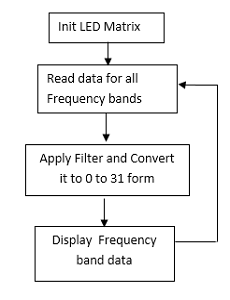
The implementation of Frequency analyzer is as follow:
1. Init LED matrix.
2. Start task to get audio frequency data and send it to LED Matrix.
2.1. Get audio frequency data for all band at once.
2.2. For each data in ith band.
2.2.1. Apply filter and divide result by 128 to get proper data between 0 to 32.
2.2.2. Send row, color and frequency information to update matrix.
Implementation
This section includes implementation, but again, not the details, just the high level. For example, you can list the steps it takes to communicate over a sensor, or the steps needed to write a page of memory onto SPI Flash. You can include sub-sections for each of your component implementation.
Audio Decoder
Text
Bluetooth and Android App
Implementation from the Android App side is as follows:
1. Try to form a successful Bluetooth connection with the HC-05 module. On success, change the 'Connection Status' indicator to indicate this. At any point if the Bluetooth Connection fails, change the Connection Status indicator and prevent all further communication with Toast error messages while trying to continuously reconnect. This functionality runs as a separate thread on the App.
2. On successful connection, receive, parse and display the song list as a List.
3. Transmit control signals as per user's activity to the SJOne board.
Frequency Decoder
The software Implementation to Init frequency analyzer is as follow:
1. Select ADC pin 2. Select GPIO pin direction for reset pin and ST pin
   adc.adcSelectPin(adc.ADC_PIN_0_26);
   LPC_GPIO1->FIODIR  |= (1 << RS) | (1 << ST);
The software Implementation to Getting data for all bands are as frequency analyzer is as follow:
1. reset ST pin. 2. Give delay required to get data. 3. Read data from ADC pin. 4. Set ST pin.
    LPC_GPIO1->FIOPIN &= ~(1 << ST);
    delay_us(40);
    val[i] = adc.readADCVoltageByChannel(3);
    LPC_GPIO1->FIOPIN |= (1 << ST);
LED Matrix
The software Implementation to Init LED matrix is as follow:
1. Set Direction of all GPIO pin to output mode
2. Set GPIO pins to 0.
   LPC_GPIO0->FIODIR  |= (1 << r1) | (1 << b1);
   LPC_GPIO1->FIODIR  |= (1 << r2) | (1 << b2);
   LPC_GPIO1->FIODIR  |= (1 << clk) | (1 << oe);
   LPC_GPIO1->FIODIR  |= (1 << a) | (1 << c);
   LPC_GPIO2->FIODIR  |= (1 << b);
   LPC_GPIO2->FIODIR  |= (1 << g1)|(1 << g2)
   LPC_GPIO2->FIODIR  |= (1 << lat);
   LPC_GPIO1 ->FIOCLR = (1 << a);
   LPC_GPIO1 ->FIOCLR = (1 << b);
   LPC_GPIO1 ->FIOCLR = (1 << c);
   LPC_GPIO1->FIOCLR = (1 << clk);
   LPC_GPIO1->FIOCLR = (1 << oe);
   LPC_GPIO2->FIOCLR = (1 << lat);
The software Implementation to update LED matrix is as follow:
1. Disable output.
2. Disable latch.
3. Select the row using A,B and C pins.
4. Reset all the LED’s in selected row.
Light up colored row depending on value of frequency band and it’s value.
5. Enable output.
6. Enable latch.
   LPC_GPIO1->FIOSET = (1 << oe);
   LPC_GPIO2->FIOSET = (1 << lat);
   (select_line & 0x1) ? LPC_GPIO1 ->FIOSET = (1 << a) : LPC_GPIO1 ->FIOCLR = (1 << a);
   (select_line & (0x1<<1)) ? LPC_GPIO2 ->FIOSET = (1 << b) : LPC_GPIO2 ->FIOCLR = (1 << b);
   (select_line & (0x1<<2)) ? LPC_GPIO1 ->FIOSET = (1 << c) : LPC_GPIO1 ->FIOCLR = (1 << c);
   for (int i = 32; i > 0; i--) {
       if (i > len1) {
           LPC_GPIO0 ->FIOCLR = (1 << r1) | (1 << b1);
           LPC_GPIO2 ->FIOCLR = (1 << g1);
       }
       else {
           (color &  0x1) ? LPC_GPIO0 ->FIOSET= (1 << r1) : LPC_GPIO0 ->FIOCLR = (1 << r1);
           (color & (0x1<<1)) ? LPC_GPIO0 ->FIOSET= (1 << b1) : LPC_GPIO0 ->FIOCLR = (1 << b1);
           (color & (0x1<<2)) ? LPC_GPIO2 ->FIOSET= (1 << g1) : LPC_GPIO2 ->FIOCLR = (1 << g1);
       }
       if (i > len2) {
           LPC_GPIO1 ->FIOCLR = (1 << r2) | (1 << b2);
           LPC_GPIO2 ->FIOCLR = (1 << g2);
       }
       else {
           (color &  0x1) ? LPC_GPIO1 ->FIOSET= (1 << r2) : LPC_GPIO1 ->FIOCLR = (1 << r2);
           (color & (0x1<<1)) ? LPC_GPIO1 ->FIOSET= (1 << b2) : LPC_GPIO1 ->FIOCLR = (1 << b2);
           (color & (0x1<<2)) ? LPC_GPIO2 ->FIOSET= (1 << g2) : LPC_GPIO2 ->FIOCLR = (1 << g2);
       }
       LPC_GPIO1->FIOSET = (1 << clk);
       LPC_GPIO1->FIOCLR = (1 << clk);
   }
   LPC_GPIO1->FIOCLR = (1 << oe);
   LPC_GPIO2->FIOCLR= (1 << lat);
Testing & Technical Challenges
1. Understanding the speed of communication between SJOne-memory card and SJOne-MP3 decoder. It was a producer-consumer problem that we were facing which was playing the song is a distorted way. We had a hard time figuring out which communication had the timing issue.
2. Care needs to be taken to have mutual exclusion while using the SPI bus between the task that reads data from SD card and the task that transmits data to the audio decoder.
Suggestions:
1. If someone would want to use this particular decoder, then we would recommend looking through sample Arduino code that comes as part of the software package to C code. It would give a good head-start to how the decoder operates on default parameters.
<Bug/issue name>
1. Late arrival of PCB.
Conclusion
Conclude your project here. You can recap your testing and problems. You should address the "so what" part here to indicate what you ultimately learnt from this project. How has this project increased your knowledge?
Project Video
Upload a video of your project and post the link here.
Project Source Code
References
Acknowledgement
Any acknowledgement that you may wish to provide can be included here.
References Used
List any references used in project.
Appendix
You can list the references you used.
