S18: Spark - MP3 Music Player with Audio Spectrum
Contents
Spark - MP3 Music Player with Audio Spectrum
Abstract
The project aims to build an embedded system based music system that also displays 7 bands of frequency spectrum on an LED display. Two SJOne (LPC1758) boards have been used in this project. The mp3 system plays music through a speaker interfaced with the board. A mobile application is used to remotely control the mp3 system using Bluetooth. The app sends the control signals like the start and stop signal to play music as well as switch the song and modify volume. The playlist for music will be stored on an SD card mounted on the SJOne board. An audio decoder is required as a mediator between speaker and SJone board. It will read data from SD card using SPI interface, convert this data into audio data and send to the speaker. Another SJOne board reads the audio frequency and divides into 7 bands that is displayed on 16X32 RGB LED.
Objectives & Introduction
Introduction
The project is divided into five different parts which include the following functionalities implemented:
1. Audio Decoder
- Reading the songs from memory card
- Sending the song to the audio decoder
- Reading commands from the Android app and perform appropriate actions like play, pause, volume etc
2. Audio Frequency Analyzer
- Converting the audio input into an ADC output.
- Parsing and then making a valid data of it that can be represented in the RGB LED Matrix.
3. RGB LED Matrix
- Displaying the dynamic frequencies of the audio signals in multiple colors
4. Android App
- Creating a basic Android App for the operation of our mp3 player
5. PCB design
- Create an innovative PCB design where we could just plug the components in the PCB
All the above tasks were worked on in parallel among all the team members.
NOTE: All the drivers that we have used in this project are the ones we have written as a part of our assignment.
Objectives
- Identify the pins and interface the following circuit
- Audio Decoder
- Audio Frequency Decoder
- RGB LED matrix
- Understand the data sheet and implement the following functionalities
- Create Sample Android App
- Audio Decoder - Play one sample song, connect with Android App
- Audio Frequency Decoder - Recognise Individual frequencies from a given sample song
- RGB LED matrix - Light up the LED and try displaying a random pattern
- Complete Each Functional Block and Integrate
- Integrate audio decoder and audio frequency decoder
- Integrate equalizer and RGB LED matrix
- Once the complete circuit works, design PCB
- Test the complete system for end-to-end functionality
- Make the project Demo-Ready
Team Members & Responsibilities
- Sucheta Iyer
- Interfacing the SJONE board with speakers via the audio decoder
- Soldering
- Graphic Equalizer Interfacing w/ Audio Decoder
- Sneha Sharma
- Interfacing the SJONE board with speakers via the audio decoder
- Android application
- Krishna Sai Anirudh Katamreddy
- Designed the hardware schematic
- Design and testing the PCB
- Soldering
- Ashwini Bhargava
- Interfacing the SJONE board with RGB Display
- Doyal Patel
- Interfacing the SJONE board with RGB Display
- Graphic Equalizer Interfacing w/ Audio Decoder
Schedule
| Week# | Dates Assigned for the Tasks | Task To Be Achieved | State of Tasks |
|---|---|---|---|
| 1 | 4/3/2018 | Project Abstract | Completed |
| 2 | 4/17//2018 | Order Components (MP3 Decoder,16*32 LED Display) | Completed |
| 3 | 4/24//2018 | Initialize LED screen with different colors.
Read music data from SD card through SPI. |
Completed |
| 4 | 5/1/2018 | Initializing single LED and testing it with sample algorithm with different colors(completed)
Initialize the Audio Decoder through SPI communication and read manufacturer ID - (completed) Read from Sjone board and play sample song - (completed) Read from Memory card(SJone) and play sample song - (in progress) Designed a PCB which can hold MP3 player shield and two SJOne boards. Connected circuits between MP3 player shield and one SJOne, LED matrix and second SJOne board. Communicating SJOne with android application using bluetooth. |
Completed |
| 5 | 5/8/2018 | Get audio spectrum values and display on LED.
Pass the song data received through SD card to the audio decoder Listen to sample music on headphone/speaker. Added Audio Analyzer to the PCB design. Reviewed all the circuit connections and dimensions between components pins. Ordered the PCB. Developing user interface on android application. |
Completed |
| 6 | 5/15/2018 | Soldering the PCB
Testing and Bug Fixing Final Wiki Report |
Completed |
Parts List & Cost
| Sr. No. | Component | Cost |
|---|---|---|
| 1 | SJONE board | $80 |
| 2 | Audio Decoder | $24.95 |
| 3 | 16*32 RGB Screen | $32.42 |
| 4 | PCB | $80.00 |
| 4 | Total | $297.37 |
Design & Implementation
A. Hardware Design
Audio Decoder
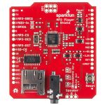
The Sparkfun MP3 Player Shield was used in this project. This includes the VS1053B MP3 audio decoder IC which decodes the supplied audio files. The audio decoder is capable of decoding audio data of various formats such as WAV, MP3, MIDI and AAC. Audio data in MP3 format is chosen for this project.
Input: MP3 audio file transmitted through SPI from SJOne Board.
Output: Audio to the headphone jack and header pins (that are given to spectrum decoder).
Bluetooth Module and Android App
The Bluetooth Module connects with the SJOne Board via UART and the data received is transmitted via Bluetooth to the SparkMusicPlayer Android App. Similarly, data sent via Bluetooth by the App is communicated via UART to the SJOne board.
1. Bluetooth Module
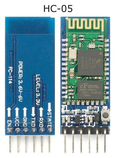
The HC-05 Bluetooth module is used in this project. This module is capable of serial communication with the microcontroller over UART and is capable of sending and receiving information via Bluetooth from paired devices.
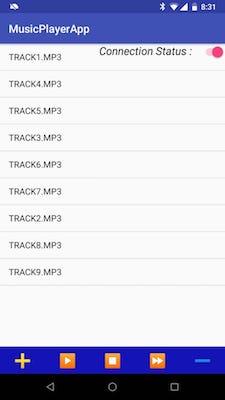
2. SparkMusicPlayer Android App
Native Android app that connects with HC-05 module (and thereby to the SJOne Board) via Bluetooth.
Data Received by the App: A list of songs available on the SD Card mounted on the SJOne board.
Data Transmitted by the App: Control signals - Play, Pause, Stop, Volume Up/Down and Song Selection from the received list of songs.
Audio Frequency Analyzer
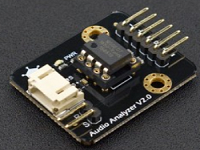
The audio analyser module uses the MSGEQ7 graphic equalizer display IC to split the music into 7 frequency bands.
The 7 frequency bands are: 63Hz, 160Hz, 400Hz, 1kHz, 2.5kHz, 6.25kHz and 16kHz.
The peak level of each band is detected and multiplexed to the output to provide a DC representation. The strobe and reset pins are used to select the DC peak output.
LED Matrix
LED display is a flat panel display, which uses an array of light-emitting diodes as pixels for a video display.
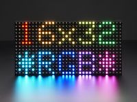
We are using the LED Matrix that has 512 RGB LEDs arranged in a 16x32 grid. It requires 12 digital pins - 6 bit data and 6 bit control.
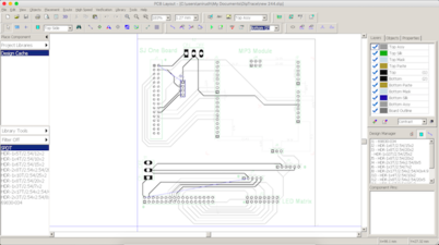
PCB Design
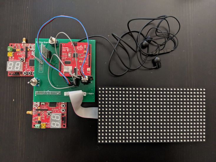
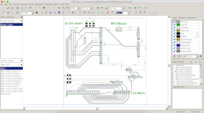
- PCB is being used to connect Sparkfun MP3 player shield, LED Matrix and Audio Analyzer with two SJOne boards.
- Using DipTrace Software to design the circuit and produce the files required to manufacture the PCB.
- Open Circuit trace lines width: 0.33 mm
- Circuit lines passing in between connection holes: 0.2 mm
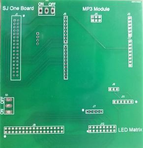
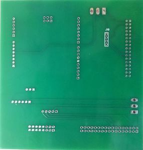
Boards and Components Placements on PCB:
- Two SJOne boards can be fitted into the top left and bottom left two 2*16 pins under SJONE Board name printed text.
- SJOne board on the Top left is connected to MP3 Player Shield and Bluetooth
- MP3 Player goes on pins below MP3 Module printed text on top right of the board.
- Bluetooth goes into four pins between SJOne and MP3 Player Shield on top left of the board.
- Second SJOne board on the bottom left is connected LED Matrix and Audio Frequency Analyzer.
- LED Matrix is connected to 2*8 pins next LED Matrix printed text on the bottom right side of the board.
- Audio Frequency Analyzer is placed into J11 and J7 in between MP3 Player and LED Matrix.
- Two switches are being used to supply voltage from SJOne boards to MP3 Player and LED Matrix
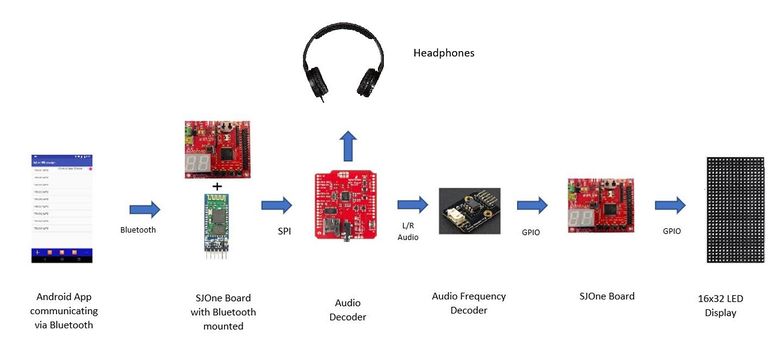
B. Hardware Interface
The following block diagram gives the system overview of the entire project.
Audio Decoder
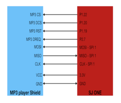
The Audio Decoder breakout board communicates with the SJOne board over SPI and is interfaced with the SPI-1 pins of the SJOne board as follows:
- Clock Pin (Pin 13) - SJOne SPI-1 Clock Pin
- MISO Pin (Pin 12) - SJOne SPI-1 MISO Pin
- MOSI Pin (Pin 11) - SJOne SPI-1 MOSI Pin
- MP3 CS: Chip Select Pin for the audio decoder to be activated while sending control signals.
- MP3 DCS: Chip Select Pin for the audio decoder to be activated while sending audio data signals.
- MP3 RST: Reset pin for the audio decoder.
- MP3 DREQ: Data Request Pin. Audio decoder signals that it is ready to accept next 32 bytes of audio data.
- VCC pin - SJOne 3.3V pin
- GND pin - SJOne GND Pin
Bluetooth and Android App
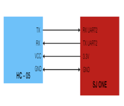
The HC-05 Bluetooth module is used in this project. It communicates with the SJOne board over UART and is interfaced with the UART2 pins of the SJOne board as follows:
- HC-05 RX pin - SJOne UART2 TX pin
- HC-05 TX pin - SJOne UART2 RX pin
- VCC pin - SJOne 3.3V pin
- GND pin - SJOne GND Pin
Audio Frequency Analyzer
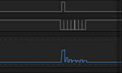
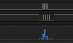
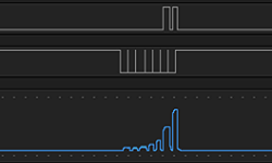
In the audio analyser, strobe and reset pins are used to select the DC peak output. Reset high resets the multiplexor. Reset low enables the strobe pin. At the leading edge of the first strobe, the first frequency band 63Hz is on the output. On each additional leading edge strobe the next frequency band(160Hz, 400Hz, 1kHz, 2.5kHz, 6.25kHz, 16kHz) is detected.
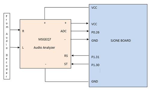
This analyser takes input from Audio decoder for left and right side music. SJOne outputs values of RS and ST pins and reads input data from S pin which is connected to ADC pin (P0.26) of SJOne.
- Audio Analyzer S pin -> SJOne P0.26 pin (ADC)
- Audio Analyzer RS pin -> SJOne P1.31 pin
- Audio Analyzer ST pin -> SJOne P1.30 pin
- Audio Analyzer + pin -> SJOne VCC pin
- Audio Analyzer - pin -> SJOne GND pin
LED Matrix
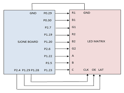
To display frequency spectrum of music input adafruit’s 16 x 32 LED Matrix is used. It is interfacing with LPC1758 using multiple GPIO pins. The LED matrix is connected to LPC1758 board by connecting three select pins to select rows (A, B and C), selection of colors using (R1,B1,R2,B2,G1,G2), Clock (clk), OE (Output enable), and Latency (LAT) of the LED matrix to GPIO pins of LPC1758 board shown as bellow:
C. Software Design
Audio Decoder
The audio decoding works in following phases which are divided into following functionalities
- Send Song list to App once upon Bluetooth Connection.
- BluetoothReceive Task: This task receives the commands from Android App via Bluetooth
- GetSong Task: This task reads the audio data from the SD Card mounted on the SJOne board through SPI. 512 bytes of data are read at a time and this data is pushed to a FreeRTOS Queue (SongQueue).
- PlaySong Task: This task sleeps on the SongQueue. When data is available it is parceled into 32-byte chunks (from 512 bytes input chunk from the queue) and transmitted over SPI to the audio decoder breakout board.
- Change Controls: This task runs in alternate with PlaySong Task because at one time we can either send the song or the control, not both at the same time. So based on what command we receive from Android App, the command parameters are changed. When this task runs, it refreshes the parameters with new parameters.
The list of all the commands that we can change are:
- Select Song from list displayed on the App
- Play
- Pause
- Stop
- Volume up
- Volume Down
- Fast Forward
Bluetooth and Android App
The project requires that the Android phone pair with the HC-05 Bluetooth device prior to using the SparkMusicPlayer App. Following this, communication follows these steps:
1. On launch, the Android device forms a successful connection with the HC-05 Bluetooth device.
2. The App receives the list of songs available on the SD Card from the SJOne board and displays them as a list.
3. The App can now transmit control signals to the SJOne board - change the song by clicking on the appropriate song on the list, pause, play, stop, fast forward and change volume. At each action an Android Toast message confirms the action taking place.
4. Following is the interpretation of the commands received from Android App.
- *0\n ->STOP
- *1\n ->START
- *2\n ->PAUSE
- *3\n ->Volume ++
- *4\n ->Volume --
- *5\n ->Fast Forward
- *SONG_NAME ->Play that song
Audio Frequency Analyzer and LED Display
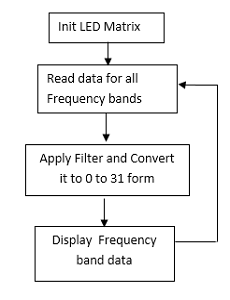
The implementation of the audio analyzer is as follow:
- Init LED matrix.
- Start task to get audio frequency data and send it to LED Matrix.
- Get audio frequency data for all band at once.
- For each data in i'th band.
- Apply filter and divide the result by 128 to get proper data between 0 to 32.
- Send row, color and frequency information to update matrix.
       // Get array pointer for all 7 frequency band result
       val = an.get_data();
       // send this data to Led Matrix
       for (int i = 0; i < 7; i++) {
           //Scalling of Input
           result = val[i] * (0.9);
           // To reduce noice
           if(result < 500)
               result = 0;
           // To convrt it in the range of 0 to 31 as we have 32 Leds in a row
           result = result / 128;
             ---- Decide rows to be choosen, and it's color, ----
           //if no leds should be on than make result to zero else number of LEDs are on
           myled.updateMatrix(color,row,result for lower row, result for upper row);
         }
In this project for each band 2 rows are used. First and Last row is used as border (7 * 2 = 14 and 2 rows for border = 16).
D. Implementation
Audio Decoder
We have a memory map of the audio decoder defined as:
  SCI_MODE 0x00
  SCI_STATUS 0x01
  SCI_BASS 0x02
  SCI_CLOCKF 0x03
  SCI_DECODE_TIME 0x04
  SCI_AUDATA 0x05
  SCI_WRAM 0x06
  SCI_WRAMADDR 0x07
  SCI_HDAT0 0x08
  SCI_HDAT1 0x09
  SCI_AIADDR 0x0A
  SCI_VOL 0x0B
  SCI_AICTRL0 0x0C
  SCI_AICTRL1 0x0D
  SCI_AICTRL2 0x0E
  SCI_AICTRL3 0x0F
Pseudo code for initialization of decoder with default parameters:
 set SCI_MODE (0x4800)
 set SCI_CLOCKF (0xBBE8)
 set SCI_VOL  (0x2222)
 set SCI_BASE (0x0076)
 set SCI_AUDATA (0xAC80)
Bluetooth Receive Task (Highest Priority):
 Receive the commands from Android App via Bluetooth
 Make changes to the control parameters that will be picked up in "change control" task
PlaySongTask (Medium Priority):
 Receive 4k Bytes in a queue with depth = 1
 if(DREQ is high)
    --Take SPI Semaphore--
    send 32 bytes of data to the audio decoder
    --Give SPI Semaphore--
 else
    run the "change control" task to change the SCI register values for audio decoder
GetSongTask (Lowest Priority):
 --Take SPI Semaphore--
 Read 4k Bytes from 'Song Name' file
 --Give SPI Semaphore--
 Send it in a queue with depth = 1
 Repeat this process till song ends
 Once the song ends, start reading the same song from the beginning.
For example,
Volume max = 0000 Volume min = FEFE XXYY, where XX is left channel and YY, is the right channel so SCI_VOL will have a volume ranging from 0000 to FEFE for a maximin to minimum range.
Bluetooth and Android App
Implementation of the Android App is as follows:
1. Try to form a successful Bluetooth connection with the HC-05 module. On success, change the 'Connection Status' indicator to indicate this. At any point if the Bluetooth Connection fails, change the Connection Status indicator and prevent all further communication with Toast error messages while trying to continuously reconnect. This functionality runs as a separate thread on the App.
2. On successful connection, receive, parse and display the song list as a List.
3. Transmit control signals as per user's activity to the SJOne board.
Audio Frequency Analyzer
Audio frequency analizer is working is most important task in order to get correct value. Incorrect initilization and in efficient delays may cause error. In this project Init and reading of data at each frequncy band is implemented based on timing diagram shown as bellow:
The software Implementation to Init frequency analyzer is as follow:
Steps:
1. Select ADC pin
2. Select GPIO pin direction for reset pin and STOBE pin
3. rest Audio frequency analizer
Implementation:
   adc.adcSelectPin(adc.ADC_PIN_0_26);
   LPC_GPIO1->FIODIR  |= (1 << RS) | (1 << ST);
   reset();
Implementation for Reset of Audio frequency analizer
       LPC_GPIO1->FIOPIN |= (1 << RS);
       delay_us(1);
       LPC_GPIO1->FIOPIN &= ~(1 << RS);
       delay_us(72);
       LPC_GPIO1->FIOPIN |= (1 << ST);
The software Implementation to Getting data for all bands are as frequency analyzer is as follow:
Steps:
1. Reset STOBE pin.
2. Give delay required to get data.
3. Read data from ADC pin.
4. Set STOBE pin.
Implementation:
    LPC_GPIO1->FIOPIN &= ~(1 << ST);
    delay_us(40);
    val[i] = adc.readADCVoltageByChannel(3);
    LPC_GPIO1->FIOPIN |= (1 << ST);
LED Matrix
The software implementation to Init LED matrix is as follow:
Steps :
1. Set Direction of all GPIO pin to output mode
2. Set GPIO pins (For a,b and c select pins and for cLK, OE, and LAT) to 0.
Implementation:
   LPC_GPIO0->FIODIR  |= (1 << r1) | (1 << b1);
   LPC_GPIO1->FIODIR  |= (1 << r2) | (1 << b2);
   LPC_GPIO1->FIODIR  |= (1 << clk) | (1 << oe);
   LPC_GPIO1->FIODIR  |= (1 << a) | (1 << c);
   LPC_GPIO2->FIODIR  |= (1 << b);
   LPC_GPIO2->FIODIR  |= (1 << g1)|(1 << g2)
   LPC_GPIO2->FIODIR  |= (1 << lat);
   LPC_GPIO1 ->FIOCLR = (1 << a);
   LPC_GPIO1 ->FIOCLR = (1 << b);
   LPC_GPIO1 ->FIOCLR = (1 << c);
   LPC_GPIO1->FIOCLR = (1 << clk);
   LPC_GPIO1->FIOCLR = (1 << oe);
   LPC_GPIO2->FIOCLR = (1 << lat);
The software Implementation to update LED matrix is as follow:
To update Led Matrix Row number, Color , Length of LED spectrum value for upper row and lower row is given.
Steps :
1. Disable output.
2. Disable latch.
3. Select the row using A,B and C pins.
4. Reset all the LED’s in selected row.
Light up colored LEDS in the row depending on value of frequency band's value.
5. Enable output.
6. Enable latch.
Implementation:
   LPC_GPIO1->FIOSET = (1 << oe);
   LPC_GPIO2->FIOSET = (1 << lat);
   (select_line & 0x1) ? LPC_GPIO1 ->FIOSET = (1 << a) : LPC_GPIO1 ->FIOCLR = (1 << a);
   (select_line & (0x1<<1)) ? LPC_GPIO2 ->FIOSET = (1 << b) : LPC_GPIO2 ->FIOCLR = (1 << b);
   (select_line & (0x1<<2)) ? LPC_GPIO1 ->FIOSET = (1 << c) : LPC_GPIO1 ->FIOCLR = (1 << c);
   for (int i = 32; i > 0; i--) {
       if (i > len1) {
           LPC_GPIO0 ->FIOCLR = (1 << r1) | (1 << b1);
           LPC_GPIO2 ->FIOCLR = (1 << g1);
       }
       else {
           (color &  0x1) ? LPC_GPIO0 ->FIOSET= (1 << r1) : LPC_GPIO0 ->FIOCLR = (1 << r1);
           (color & (0x1<<1)) ? LPC_GPIO0 ->FIOSET= (1 << b1) : LPC_GPIO0 ->FIOCLR = (1 << b1);
           (color & (0x1<<2)) ? LPC_GPIO2 ->FIOSET= (1 << g1) : LPC_GPIO2 ->FIOCLR = (1 << g1);
       }
       if (i > len2) {
           LPC_GPIO1 ->FIOCLR = (1 << r2) | (1 << b2);
           LPC_GPIO2 ->FIOCLR = (1 << g2);
       }
       else {
           (color &  0x1) ? LPC_GPIO1 ->FIOSET= (1 << r2) : LPC_GPIO1 ->FIOCLR = (1 << r2);
           (color & (0x1<<1)) ? LPC_GPIO1 ->FIOSET= (1 << b2) : LPC_GPIO1 ->FIOCLR = (1 << b2);
           (color & (0x1<<2)) ? LPC_GPIO2 ->FIOSET= (1 << g2) : LPC_GPIO2 ->FIOCLR = (1 << g2);
       }
       LPC_GPIO1->FIOSET = (1 << clk);
       LPC_GPIO1->FIOCLR = (1 << clk);
   }
   LPC_GPIO1->FIOCLR = (1 << oe);
   LPC_GPIO2->FIOCLR= (1 << lat);
Testing & Technical Challenges
Testing
1. Music Player:
Different scenarios were tested:
  play
  pause
  stop
  volume up
  volume down
  fast forward
  play a different song from list
2. Audio Analyzer:
To test output of audio analyzer Logic analyzer is used. Audio of different frequency bands are choosen and given to audio decoder which gives input to Audio decoder. The screen-shots based on different audio input as follow:
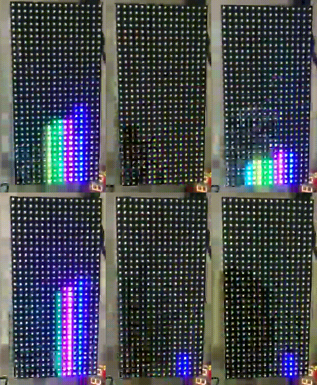
LED Matrix which will take all values from 7 frequency bands and display it on LED matrix. The output of LED matrix is as follow:
Technical Challenges
- Problem 1: Song was playing in a distorted way and we were unable to zero down on the source of the problem.
- Solution: Figuring out which of the following was causing the problem was a little difficult for us:
- Speed of communication between SJOne-memory card and SJOne-MP3 decoder. We had a hard time figuring out which communication had the timing issue.
- It was a producer-consumer problem as well.
- Another valuable takeaway during solving this issue - Care needs to be taken to have mutual exclusion while using the SPI bus between the task that reads data from SD card and the task that transmits data to the audio decoder.
- Solution: Figuring out which of the following was causing the problem was a little difficult for us:
- Problem 2: Issue faced to get output from the audio analyzer.
- Solution: To get output from audio frequency analyzer is tricky. It requires delay after strobe pin goes high. If the delay is not proper, the output can be wrong. To Solve this we tried to give little extra delay than the minimum requirement. To test this solution, we used Logic Analyzer with different frequency inputs.
- Problem 3: There was a lot of electrical noise that was being captured in the Spectrum Decoder.
- Solution: Trying to minimize that was a challenge for our team as the source of the noise was not easy to isolate. We tried to get minimum noise and discarded it. We have also used averaging of three continuous output at each band which gave us a better result. On testing with PCB circuit, we realized that the noise was considerably reduced.
- Problem 4: PCB arrived late so we had to do the soldering and hardware setup in just a couple hours. Delivery of the complete product turned out to be time critical for us.
Suggestions
- We would recommend first playing a sample song from SJOnce board to the audio decoder and get it to play. It can be as simple as recording "Hello World" as a character array and getting it to play as an output. It would give a good head-start on how the decoder operates on default parameters.
- Once you have successfully done that, then try and read data from memory card and send it to the audio decoder. Breaking the tasks into small problems helps debug the code easy.
- Remember to guard you SPI bus with a mutex as the memory card and audio decoder use the same SPI bus.
Conclusion
Executing this project was a great experience. We learnt about operating multiple devices using a single SPI bus and dealing with producer-consumer issues. Further we had the experience of interfacing multiple devices such as Bluetooth, Audio Decoder, Spectrum Analyzer and an LED matrix. An important lesson we learned was that the PCB must be ordered as early as possible so that it may arrive on time!
Project Video
Project Source Code
Source Code for the Audio Decoder
Source Code for the Frequency Spectrum Analyzer and LED Matrix
References
Acknowledgement
All these people deserve a shout out without whom this project would not have been completed.
- First and foremost, Preet for his guidance throughout this project and for being an awesome professor.
- All the ISA team, Prashant, Shruthi, Mohdi, Pushpender and Venkat, for replying to our queries as fast as possible.
- The fellow members of the class for having good discussions during the course that led to resolving many problems. Also, many thanks to members of fellow teams for providing valuable feedback.
