S16: OpenSJ Bluz
Contents
Grading Criteria
- How well is Software & Hardware Design described?
- How well can this report be used to reproduce this project?
- Code Quality
- Overall Report Quality:
- Software Block Diagrams
- Hardware Block Diagrams
- Schematic Quality
- Quality of technical challenges and solutions adopted.
OpenSJ Bluz
Abstract
This section should be a couple lines to describe what your project does.
Objectives & Introduction
Show list of your objectives. This section includes the high level details of your project. You can write about the various sensors or peripherals you used to get your project completed.
Team Members & Responsibilities
- Dhruv Kakadiya
- Surojit Sengupta
Schedule
Show a simple table or figures that show your scheduled as planned before you started working on the project. Then in another table column, write down the actual schedule so that readers can see the planned vs. actual goals. The point of the schedule is for readers to assess how to pace themselves if they are doing a similar project.
Team Schedule
| SI No. | Start Date | End Date | Task | Team Member | Status | Actual Completion Date |
|---|---|---|---|---|---|---|
| 1 | 03/12/2016 | 03/22/2016 |
|
- | Completed | 03/21/2016 |
| 2 | 03/22/2016 | 03/27/2016 | Following up on hardware components procurement through team discussions, PCB design | Dhruv | Completed | 03/26/2016 |
| 3 | 03/27/2016 | 03/29/2016 | Finding out a way to program Bluefruit Module using SW(serial wire) interface. | Dhruv | Completed | 03/30/2016 |
| 4 | 03/29/2016 | 04/1/2016 | Implement HRS(Heart Rate Sensor) Profile on BlueFruit Module | Dhruv, Surojit | Completed | 04/1/2016 |
| 5 | 04/1/2016 | 04/4/2016 | Implement Nordic UART Service to send and receive data from UART ( Wireless UART ) and check communication using Nordic Master Control Panel Application | Dhruv, Surojit | Completed | 04/4/2016 |
| 6 | 04/4/2016 | 04/10/2016 | Create individual BLE profile for each sensor (Accelerometer, Temperature, Light etc.) | Dhruv, Surojit | Completed | 04/12/2016 |
| 7 | 04/10/2016 | 04/25/2016 | Create simple BLE Android application to receive sensor data in appropriate BLE service | Dhruv, Surojit | Incomplete | - |
| 8 | 04/25/2016 | 04/30/2016 | Create user defined GATT services and broadcast individual sensor data in individual services and plot real time graphs on Android | Surojit | Incomplete | - |
| 9 | 04/30/2016 | 05/10/2016 | PCB and Firmware testing and debugging, Pushing all data to the cloud | Dhruv, Surojit | Incomplete | - |
Parts List & Cost
Give a simple list of the cost of your project broken down by components. Do not write long stories here.
Design & Implementation
The design section can go over your hardware and software design. Organize this section using sub-sections that go over your design and implementation.
Hardware Design
Discuss your hardware design here. Show detailed schematics, and the interface here.
Technical Specifications for Bluefruit BLE module
- Nordic nRF51822 - ARM Cortex M0 core running at 16MHz
- 256KB flash memory
- 32KB SRAM
- Peak current draw <20mA (radio actively transmitting/receiving)
- Transport: UART typically @ 9600 baud with HW flow control (Configurable)
- 5V-safe inputs
- On-board 3.3V voltage regulation
- Bootloader with support for safe OTA firmware updates
- Supports Central and Peripheral mode
- Supports Bluetooth Smart protocol stacks
- On air compatible with nRF24L series
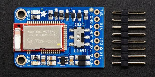
Front side breakouts
Power pins
- VIN - This is the power supply for the module, supply with 3.3-16V power supply input. This will be regulated down to 3.3V to run the chip
- GND - The common/GND pin for power and logic
UART pins
- TXO - This is the UART Transmit pin out of the breakout (Bluefruit LE --> SJOne), it's at 3.3V logic level.
- RXI - This is the UART Receive pin into the breakout (SJOne--> Bluefruit LE). This has a logic level shifter on it, you can use 3-5V logic.
- CTS - Clear to Send hardware flow control pin into the the breakou (SJOne--> Bluefruit LE). Use this pin to tell the Bluefruit that it can send data back to the SJOne over the TXO pin. This pin is pulled high by default and must be set to ground in order to enable data transfer out! If you do not need hardware flow control, tie this pin to ground it is a level shifted pin, you can use 3-5V logic
- RTS - Read to Send flow control pin out of the module (Bluefruit LE --> SJOne). This pin will be low when its fine to send data to the Bluefruit. In general, at 9600 baud we haven't seen a need for this pin, but you can watch it for full flow control! This pin is 3.3V out
Other pins
- MOD - Mode Selection. The Bluefruit has two modes, Command and Data. You can keep this pin disconnected, and use the slide switch to select the mode. Or, you can control the mode by setting this pin voltage, it will override the switch setting! High = Command Mode, Low = UART/DATA mode. This pin is level shifted, you can use 3-5V logic
- DFU - Setting this pin low when you power the device up will force the Bluefruit LE module to enter a special firmware update mode to update the firmware over the air. Once the device is powered up, this pin can also be used to perform a factory reset. Wire the pin to GND for >5s until the two LEDs start to blink, then release the pin (set it to 5V or logic high) and a factory reset will be performed.
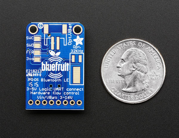
Reverse side breakouts
- Reverse side pin outs for Bluefruit module is as per below.
- Opt VBat - If you fancy, you can solder on a JST 2-PH connector, this will let you easily plug in a Lithium Ion or other battery pack. This connector pad is diode protected so you can use both Vin and VBat and the regulator will automatically switch to the higher voltage
- Opt. 32 KHz - If you're doing some funky low power work, we wanted to give you the option of solderin in a 32khz oscillator. Our firmware doesn't support it yet but its there!
- SWC - This is the SWD clock pin, 3v logic - for advanced hackers!
- SWD - This is the SWD data pin, 3v logic - for advanced hackers!
- 3Vo - This is the output from the 3V regulator, for testing and also if you really need regulated 3V, up to 250mA available
- FCR - This is the factory reset pin. When all else fails and you did something to really weird out your module, tie this pad to ground while powering up the module and it will factory reset.
Hardware Interface
In this section, you can describe how your hardware communicates, such as which BUSes used. You can discuss your driver implementation here, such that the Software Design section is isolated to talk about high level workings rather than inner working of your project.
Software Design
Show your software design. For example, if you are designing an MP3 Player, show the tasks that you are using, and what they are doing at a high level. Do not show the details of the code. For example, do not show exact code, but you may show psuedocode and fragments of code. Keep in mind that you are showing DESIGN of your software, not the inner workings of it.
Needed Software tools to program nRF51822 Bluefruit module
- nRFgo Studio
- nRF51 Software Development Kit (SDKv8.0.0)
- Keil IDE
- S110 nRF51822 SoftDevice
- S110 SoftDevice programming tools
- Nordic Master Control Panel Android/iOS application
- Segger J-Link Programmer
Implementation
This section includes implementation, but again, not the details, just the high level. For example, you can list the steps it takes to communicate over a sensor, or the steps needed to write a page of memory onto SPI Flash. You can include sub-sections for each of your component implementation.
Testing & Technical Challenges
Describe the challenges of your project. What advise would you give yourself or someone else if your project can be started from scratch again? Make a smooth transition to testing section and described what it took to test your project.
Include sub-sections that list out a problem and solution, such as:
My Issue #1
Discuss the issue and resolution.
Conclusion
Conclude your project here. You can recap your testing and problems. You should address the "so what" part here to indicate what you ultimately learnt from this project. How has this project increased your knowledge?
Project Video
Upload a video of your project and post the link here.
Project Source Code
References
Acknowledgement
Any acknowledgement that you may wish to provide can be included here.
References Used
List any references used in project.
- Adafruit Bluefruit LE UART Friend module datasheet
- nRF51822 Documentation
- nRF51_SDK_v10 - Software Development Kit for Nordic BLE development
- Nordic Development Tutorials and forum
- Nordic Training Videos
- Segger J Link Debugger tool
- Bluefruit LE Sniffer
- Python api for BLE sniffer
- DFU Updates
- Sample firmware images for Bluefruit module
- Bluefruit Arduino example codes
Appendix
You can list the references you used.
Scratch pad
1. Collect sensor data from all the sensors a. IMU b. Temp c. Light
Collect values and transmit over individual BLE service nrf51822 -> no OS. Put OS on top of that and replace NORDIC BLE UART , with own ble service and use specific UUID
Profiles ->
Light Sensor (Notify/Indicate/Raw read)
Reading for BLE overview - http://mbientlab.com/blog/bluetooth-low-energy-introduction/
BLE Part https://www.adafruit.com/product/2479
Try and implement FreeRTOS / RTX on the AdaFruit BLE nordic Part
Surojit - Start with the Android side of things [04/23/2016] ==> Balance a ball based on mobile app based on IMU reading from board. ==> Real time graph for each of the Sensor Readings. ==> Push data on to cloud
- Dhruv- 1 sensor and BLE nordic and tune it , Make BLE profile (Temperature) [04/23/2016]
- Dhruv- 1 more sensor and BLE nordic , Make BLE profile (Light) [04/23/2016]
- Surojit - 1 more sensor and BLE nordic , Make BLE profile (IMU) [04/17/2016]
- Dhruv - FreeRTOS [04/23/2016]
Extra Credit Over the Air Update (OTA)

