S14: Modular Security System
Contents
MODULAR SECURITY SYSTEM
Abstract
Most people lack security systems in their homes or they have outdated security systems. The main thing preventing them is the high cost of alarm systems and the cost of professional installation. The Modular Security System can monitor the homes and alert user via an email message anytime there is any in intrusion. The security system will also provide the users capability to control the system via an Android App.
Objectives & Introduction
The aim of this project is to deliver a low-powered security system that can be controlled wirelessly through common consumer electronic devices, such as desktop and laptop computers, tablets, or phones. Intrusion detection will be performed by various sensors that will communicate wirelessly to a base station. The base station will then push detection events to the user’s devices.
Most security systems on the market forward alerts to alarm companies that then inform users of alert events as a service provided for their continued security subscription. This project aims to change the industry standard by providing a security system that provides direct alerts to users. In pushing this project into fruition, the topics of embedded systems and microcontrollers, mesh networks, wireless fidelity and TCP/IP, and mobile applications will be explored. This development team hopes to gain skills from working on this project and to pass on the knowledge gained from this experience through this report.
Team Members & Responsibilities
- Team Member 1: Surinder Pal Singh
- Sensor Node Implementation
- Interface MP3 Decoder with Base Station
- Design Android App
- Testing
- Report and Documentation
- Team Member 2: Tianxiong Zhao
- FreeRTOS Implementation of MP3
- Testing
- Team Member 3: Nathaniel Natividad
- Base Station Implementation
- Email Alert to User
- Testing
- Report and Documentation
Schedule
Show a simple table or figures that show your scheduled as planned before you started working on the project. Then in another table column, write down the actual schedule so that readers can see the planned vs. actual goals. The point of the schedule is for readers to assess how to pace themselves if they are doing a similar project.
| Week# | Date | Task | Actual |
|---|---|---|---|
| 1 | 3/28 |
|
Completed? Problems Encountered? |
| 2 | 04/04 |
|
|
| 3 | 04/11 |
|
|
| 4 | 04/18 |
|
|
| 5 | 04/25 |
|
|
| 6 | 05/02 |
|
|
| 7 | 05/09 |
|
|
| 8 | 05/16 |
|
Parts List & Cost
| Part | Quantity | Cost Each | Total Cost |
|---|---|---|---|
| SJSU ONE Board | 1 | $60 | $60 |
| Custom Designed Board for Sensor Node | 1 | $70 | $70 |
| PIR Motion Sensor | 1 | $9.95 | $9.95 |
| Magnetic Contact Sensor | 1 | $4.99 | $4.99 |
| MP3 Decoder | 1 | $39.99 | $39.99 |
| Wi-Fi Module | 1 | $39.95 | $39.95 |
| Battery Packs | 2 | $4.99 | $9.98 |
| LCD Display | 1 | $19.99 | $19.99 |
Design & Implementation
Hardware Design
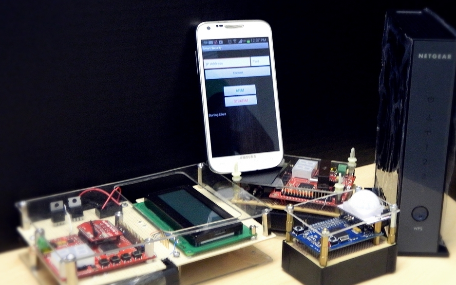
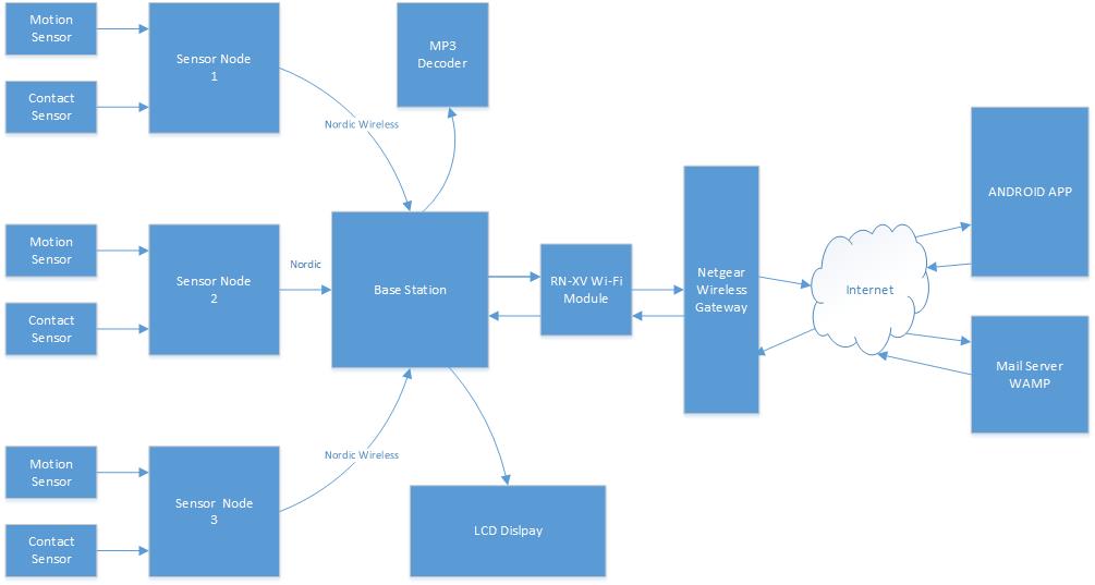
The security system is composed of several different components like sensor nodes, base station, web server,mp3 decoder and an android application. The sensor nodes contain a PIR motion detector and magnetic contact sensor. Anytime the node detects any motion activity or instruction via contact sensor, it sends a message to base station via Nordic Wireless. The base station analyzes the message and it alerts the user by sending an email message to the web server. The base station establishes connection to the web server via Wi-Fi, which is interfaced to the base station via UART. The web server then alerts the user about the intrusion via email within couple of seconds. The base station also updates the status on the LCD. Anytime the System is armed, disarmed or the alarm is triggered, the MP3 decoder plays the sound.
System Design
Base Station Schematic
Sensor Node Schematic
Hardware Interface
In this section, you can describe how your hardware communicates, such as which BUSes used. You can discuss your driver implementation here, such that the Software Design section is isolated to talk about high level workings rather than inner working of your project.
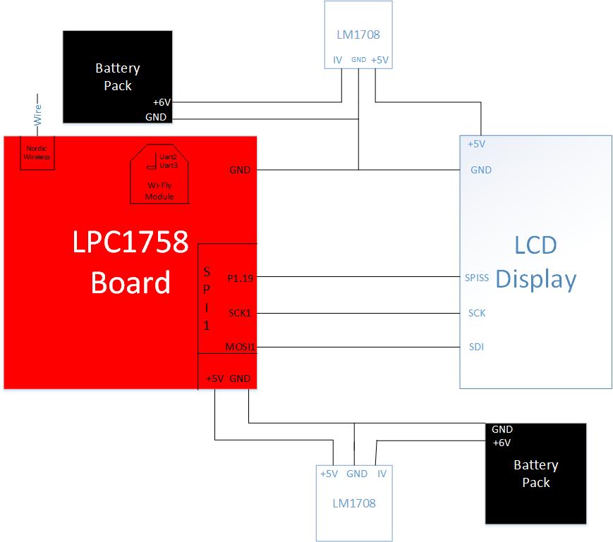
The modular security system consists of many different hardware components. For the base station, the SJSU One Micron-controller is interfaced to a LCD, MP3 Decoder, a Wi-Fi module. The LCD is interfaced via Serial Peripheral Interface Bus. The port connections are shown in Table 1. The RN-XV WI-Fly module is interfaced to the micro-controller via UART2. The MP3 decoder is interfaced to the GPIO pins P0.0 and P0.1. The sensor nodes have a magnetic contact sensor and a PIR motion sensor interfaced to P0.0 and P0.1 respectively. Table 2 shows the interface connections between the micro-controller and the MP3 decoder.
| SJSU One Board - LPC1758 | LCD |
|---|---|
| P1.19 | Pin1 - SPISS (Slave Select) |
| SCK1 | Pin3 - SCK |
| MOSI | Pin4 - SDI (Serial Data In) |
| GND | Pin5 - GND |
Table 1
| SJSU One Board - LPC1758 | MP3 Decoder Board |
|---|---|
| P0.0 | P1.19 |
| P0.1 | P1.17 |
| GND | GND |
Table 2
Software Design
Show your software design. For example, if you are designing an MP3 Player, show the tasks that you are using, and what they are doing at a high level. Do not show the details of the code. For example, do not show exact code, but you may show psuedocode and fragments of code. Keep in mind that you are showing DESIGN of your software, not the inner workings of it.
Base Station
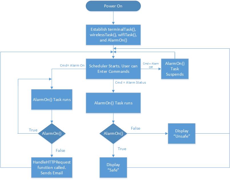
Software Architecture Design Base Station
Sensor Node
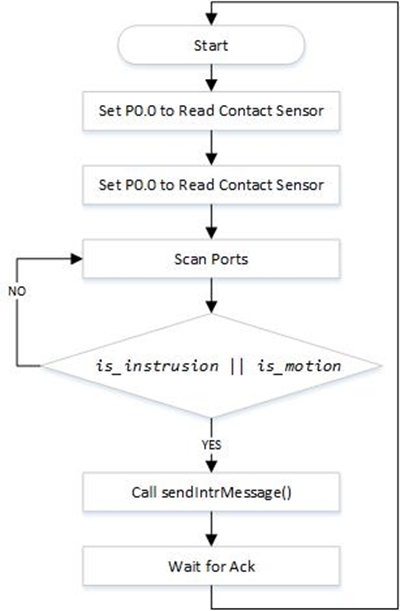
Flow Diagram Sensor Node
Android App
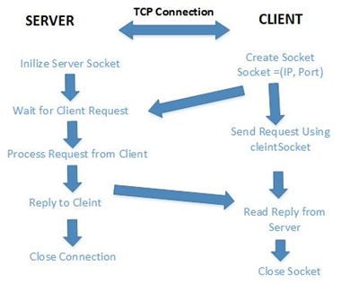
TCP Connection
Implementation
This section includes implementation, but again, not the details, just the high level. For example, you can list the steps it takes to communicate over a sensor, or the steps needed to write a page of memory onto SPI Flash. You can include sub-sections for each of your component implementation.
Base Station
Sensor Node
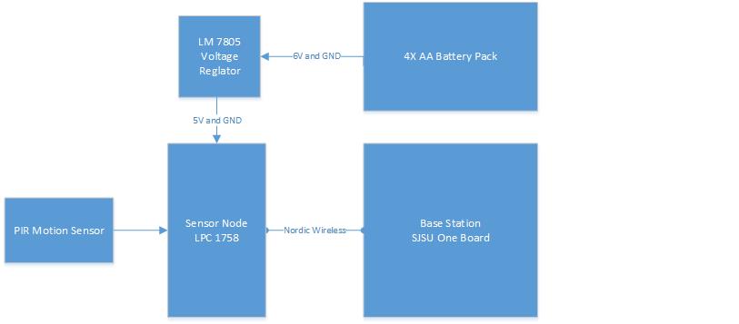
The sensor node is interfaced to a PIR motion sensor and a magnetic contact sensor. The magnetic contact sensor is interfaced to P0.0 and the motion sensor is interfaced to P0.1 of the SJSU micro-controller. Below is an example of how the two pins are set as inputs to get the readings of the two sensors. The inputs from each sensor is stored in the bool variables.
bool is_instrusion = !!(LPC_GPIO0->FIOPIN & (1 << 0));
bool is_motion = !!(LPC_GPIO0->FIOPIN & (1 << 1));
Two bool values are used in an if statement to check the status of individual sensor. If the motion is detected, the statements in if statement are executed and sendIntrMessage() function is called. Similarly if it detects any intrusion via contact sensor, then the statements inside the if else case gets executed. The sendIntrMessage() function establishes communication with the base station via Nordic Wireless and sends an intrusion message. In the sendIntrMessage() function, another function wireless_send() is called, and the parameters passed to that function include address of the base station, message string, string size, and number of hops to base station. Below is an snippet of the function, where the number of hops and address of base station are stored in a char, and then those variables are passed into the function called wireless_send().
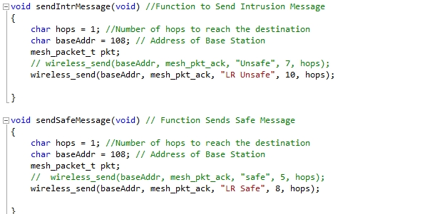 Figure: Function to send intrusion message to the Base Station
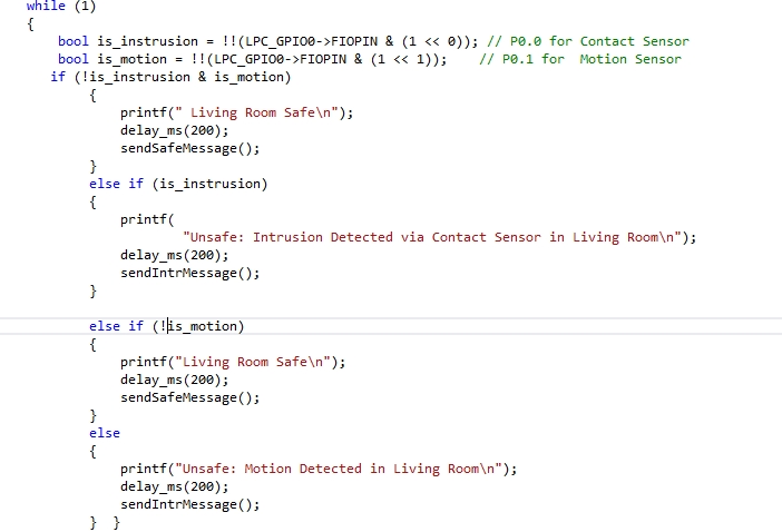 Figure: Initialization of GPIO pins in the main
Android App
The implementation of the Android App is done using Android SDK ADT Bundle. The bundle is great for new android developers as it contains everything to begin developing apps. The software tools included in the bundle are Eclipse + ADT plug-in, Android SDK Tools, the latest Android platform, the latest Android system image for the emulator.
The implementation of the Android App is mostly done in three files, and those are activity_main.xml, MainActivity.java and AndroidManifest.xml.The activity_main. xml file contains all the code for the user interface and the layout of the Android App. The MainActivity.java file includes all the back-end information for the user interface. It contains the code for the event listeners for the buttons and text-boxes. The third file named AndroidManifest.xml contains all the permissions to use hardware and code.
The layout of the app is designed by adding the necessary buttons such as Connect, Arm, and Disarm. Text-boxes to capture user input for IP address and port number are also added to the user interface. This make it very convenient for the user because if the there are any changes to the IP address or the port number of the base station’s Wi-Fi, then nothing in the Android App has to changed. The user can simply type in the new IP address and the port number to establish TCP connection.A single button for Connect and Disconnect is used. Once the connection is established, the name of connection button changes from Connect to Disconnect. To make the application user friendly, the user will get a printed message once the connection is made, and if the connection is not successful an appropriate message will be displayed. For example if the user enters wrong port number, an error message will give the user some indication to correct it.
Example of how a button is added to the user interface
<Button
   android:id="@+id/connect"
   android:layout_width="fill_parent"
   android:layout_height="wrap_content"
   android:text="Connect"
/>
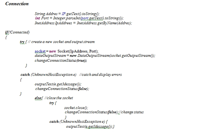
Next an event listener for each button is added in the MainActivity java file. The TCP/IP communication between the Android App and the base station is done using sockets. A new socket gets created when the user enters the port number and IP address.The client then sends a request to the server with dataOutStream. If the connection is successful, the connection status changes to true, else the connection status is changes to false and appropriate exception is printed.
The code below shows how a socket is created using the IP address and port number entered by user and connection to the server is established.
Testing & Technical Challenges
Describe the challenges of your project. What advise would you give yourself or someone else if your project can be started from scratch again? Make a smooth transition to testing section and described what it took to test your project.
Include sub-sections that list out a problem and solution, such as:
Testing Sensor Nodes
My Issue #1
Discuss the issue and resolution.
Conclusion
Conclude your project here. You can recap your testing and problems. You should address the "so what" part here to indicate what you ultimately learnt from this project. How has this project increased your knowledge?
Project Video
Upload a video of your project and post the link here.
Project Source Code
Send me your zipped source code and I will upload this to SourceForge and link it for you.
References
Acknowledgement
Any acknowledgement that you may wish to provide can be included here.
References Used
List any references used in project.
Appendix
You can list the references you used.
