S14: Modular Security System
Contents
MODULAR SECURITY SYSTEM
Abstract
Most people lack security systems in their homes or they have outdated security systems. The main thing preventing them is the high cost of alarm systems and the cost of professional installation. The Modular Security System can monitor the homes and alert user via an email message anytime there is any in intrusion. The security system will also provide the users capability to control the system via an Android App.
Objectives & Introduction
The aim of this project is to deliver a low-powered security system that can be controlled wirelessly through common consumer electronic devices, such as desktop and laptop computers, tablets, or phones. Intrusion detection will be performed by various sensors that will communicate wirelessly to a base station. The base station will then push detection events to the user’s devices.
Most security systems on the market forward alerts to alarm companies that then inform users of alert events as a service provided for their continued security subscription. This project aims to change the industry standard by providing a security system that provides direct alerts to users. In pushing this project into fruition, the topics of embedded systems and microcontrollers, mesh networks, wireless fidelity and TCP/IP, and mobile applications will be explored. This development team hopes to gain skills from working on this project and to pass on the knowledge gained from this experience through this report.
Team Members & Responsibilities
- Team Member 1: Surinder Pal Singh
- Sensor Node Implementation
- Interface MP3 Decoder with Base Station
- Design Android App
- Testing
- Report and Documentation
- Team Member 2: Tianxiong Zhao
- FreeRTOS Implementation of MP3
- Testing
- Team Member 3: Nathaniel Natividad
- Base Station Implementation
- Email Alert to User
- Testing
- Report and Documentation
Schedule
| Week# | Date | Task | Actual |
|---|---|---|---|
| 1 | 3/28 |
|
Completed |
| 2 | 04/04 |
|
Completed |
| 3 | 04/11 |
|
Completed
|
| 4 | 04/18 |
|
Completed |
| 5 | 04/25 |
|
Completed |
| 6 | 05/02 |
|
Completed
|
| 7 | 05/09 |
|
Completed
|
| 8 | 05/16 |
|
Completed |
Parts List & Cost
| Part | Quantity | Cost Each | Total Cost |
|---|---|---|---|
| SJSU ONE Board | 1 | $60 | $60 |
| Custom Designed Board for Sensor Node | 1 | $70 | $70 |
| PIR Motion Sensor | 1 | $9.95 | $9.95 |
| Magnetic Contact Sensor | 1 | $4.99 | $4.99 |
| MP3 Decoder | 1 | $39.99 | $39.99 |
| Wi-Fi Module | 1 | $39.95 | $39.95 |
| Battery Packs | 2 | $4.99 | $9.98 |
| LCD Display | 1 | $19.99 | $19.99 |
Design & Implementation
Hardware Design
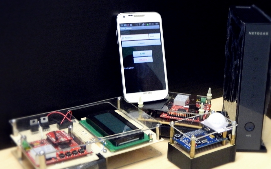
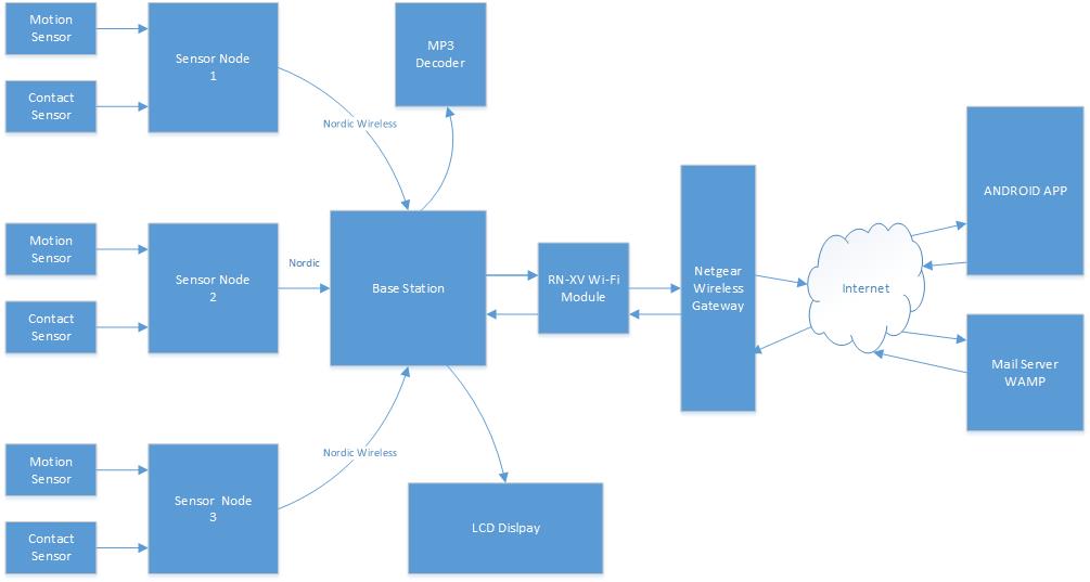
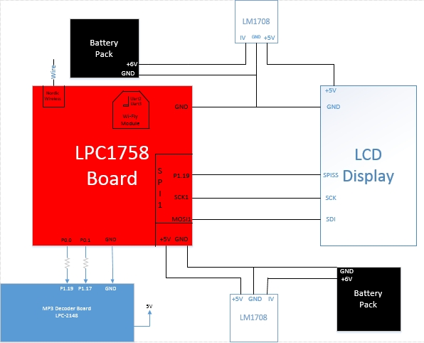
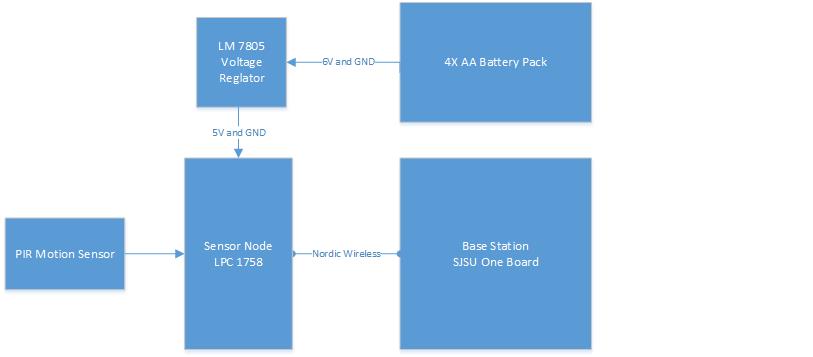
The security system is composed of several different components like sensor nodes, base station, web server,mp3 decoder and an android application. The sensor nodes contain a PIR motion detector and magnetic contact sensor. Anytime the node detects any motion activity or instruction via contact sensor, it sends a message to base station via Nordic Wireless. The base station analyzes the message and it alerts the user by sending an email message to the web server. The base station establishes connection to the web server via Wi-Fi, which is interfaced to the base station via UART. The web server then alerts the user about the intrusion via email within couple of seconds. The base station also updates the status on the LCD. Anytime the System is armed, disarmed or the alarm is triggered, the MP3 decoder plays the sound.
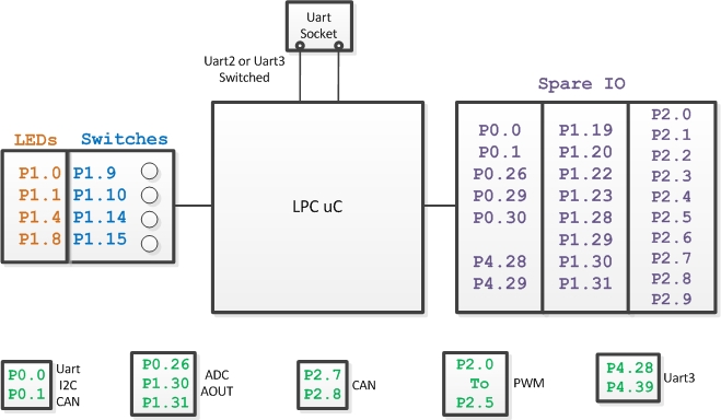
Figure1: Pin Diagram SJSU One Board - LPC 1758
Figure 2: Pin Diagram MP3 Board - LPC 2148
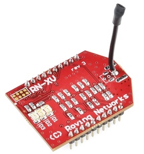
Figure 3: RN-XV Wi-Fly Module
Figure 4: System Design
Figure 5: Base Station Schematic
Figure 6: Sensor Node Schematic
Hardware Interface
The modular security system consists of many different hardware components. The base station of the system has a SJSU One micro-controller interfaced to a LCD module, MP3 Decoder board, and a Wi-Fly module. The LCD is interfaced via Serial Peripheral Interface Bus. The port connections are shown in Table 1. The RN-XV WI-Fly module is interfaced to the micro-controller via UART2. The MP3 decoder is interfaced to the board via GPIO pins P0.0 and P0.1. The sensor nodes have a magnetic contact sensor and a PIR motion sensor interfaced to P0.0 and P0.1 respectively. Table 2 shows the interface connections between the micro-controller and the MP3 decoder.
| SJSU One Board - LPC1758 | LCD |
|---|---|
| P1.19 | Pin1 - SPISS (Slave Select) |
| SCK1 | Pin3 - SCK |
| MOSI | Pin4 - SDI (Serial Data In) |
| GND | Pin5 - GND |
| SJSU One Board - LPC1758 | MP3 Decoder Board |
|---|---|
| P0.0 | P1.19 |
| P0.1 | P1.17 |
| GND | GND |
Base Station
The base station consists of the SJSU One board, LCD module, MP3 decoder board, and a Wi-Fly module. The base station includes all the functions needed to make the security system run properly. The LPC1758 board receives the packets from the sensor nodes via Nordic wireless and makes a decision based on the content in the received packet. If the message in the packet is safe, the system continues to check the sensors. If the message in the packet is unsafe, then it sends a email message to the user. The LCD is interfaced the micro-controller via SPI bus and it displays the status of the security system which gets updated anytime there is any change. The MP3 decoder plays appropriate sounds when the security system armed, disarmed and when the alarm is triggered by one of the sensors. The Wi-Fly module is interfaced to the SJSU One board via UART2. The Wi-Fly module is the communication bridge between the user and the security system. It allows the user to send commands from the Android App and receive email message during an intrusion. A web-server is used by the base station to send email alert to the user during an intrusion. The base station connects to the internet using Wi-Fly module and a gateway router, and with the right credentials can call the web server. The web server has an accessible file; it will send an email to the user whenever it receives an call. The web server that we used for this project is called WAMP server, which stands for Windows, Apache, MySQL, PHP. The WAMP server doesn’t have a send mail function when installing onto the computer. We would have to download that specific function by going to its source (http://glob.com.au/sendmail/) and download its contents onto the web server. We would make a .php file which sends an email to the user’s email address using Notepad++ and place that file into the web server. To test if the function is working, we would call the file by opening a web server and call the web server’s IP address and its file (Example: if IP address is 192.168.1.3, the website to check is 192.168.1.3/email.php). If it doesn’t work, the page should return the error in the code and can be fixed using Notepad++. We would continue doing this process until the function is able to send an email to the user.
Sensor Node
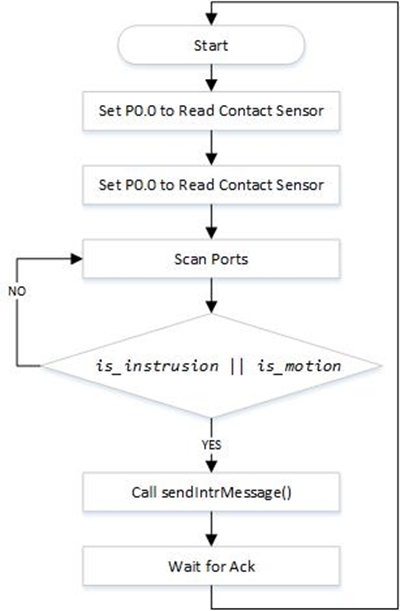
The sensor node is interfaced to a contact sensor and a motion sensor. All the implementation of the sensor node is done using C language in Eclipse IDE. The sensors are interfaced to the newly designed micro-controller. A new micro-controller board is designed to reduce power consumption by using only necessary components. First direction of the two GPIO pins, P0.0 and P0.1, of the board is set to input to read the sensor values. Using bit-masking, the input is read from P0.0 and P0.1. Next two functions are written to send the safe and intrusion messages. Within each function the wireless send function is called and the parameters passed to the function include the base station address, the message string, message string size, and number of hops. Anytime any motion is detected or any intrusion via contact sensor is detected, appropriate function will be called to send a message to the base station.
Software Design
Base Station
Figure 7: Software Architecture Design Base Station
Sensor Node
Figure 8: Flow Diagram Sensor Node
Android App
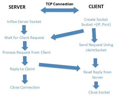
Figure 9: TCP/IP Connection
Implementation
Base Station
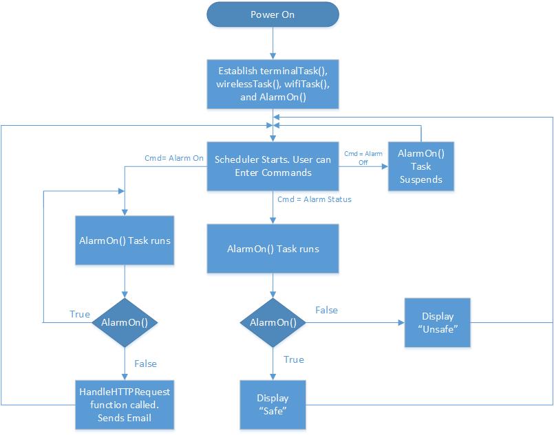
The Main.cpp file lists down all the tasks that the SJSU One board will be running when the board is powered up. The Wireless task establishes the mesh network and is responsible for tasks like sending and receiving packets between the micro-controllers. The next task in the main is the WiFi task which gets the instance of the Uart port where the Wi-Fly module is. A connection is established if the information returned to the user has a confirmed IP address for the board (having an address of 0.0.0.0 means no connection was made). With that IP address, any product with wireless connectivity can interact with the board by connecting to that IP address and port number. The next task in the main is the Alarm on task which checks the status of the sensor and takes appropriate action according the sensor readings. With all the tasks being established, the scheduler would then pop up a menu for the user to interact with the board. In the terminal task, another entry for the alarm on and and off is added.We would make our task entry by using this format, which was the same for the other terminal tasks declared.
CMD_HANDLER_FUNC(alarmHandler);
   cp.addHandler(alarmHandler, "Alarm", "Type 'Alarm <on>' to turn on system\n" "'Alarm <off>'
   to turn off system\n" "'Alarm <status>' to see status of system");
This line of code calls the addHandler function of the terminal file and adds it onto the menu. The user can type up the command “Alarm on”, “Alarm off”, and “Alarm Status" from the command terminal to get the results. The user commands from the Android App will be directed to the terminal Arm and Disarm the security system.
The MP3 decoder board is interfaced to the base station's micro-controller via GPIO pins. An 1K of inline resistor is used between the two boards to limit the current. The two GPIO pins from the base station translate into four states in the MP3 decoder board. There are three important tasks in the MP3 board, and they are buttonTask(), userInterfaceTask(), and mp3Task(). The button task initializes the GPIO pins , sets their direction to input. The task keeps listening for a signal from the base station and send it to userInterfaceTask. The userInterfaceTask initializes the SPI, I2C MP3 decoder. It decodes the singnal and determine which MP3 to play. The userInterfaceTask then queue the MP3 name to the MP3Task. The MP3 task receives the name from the queue and opens the file from the SD card. The task reads 1024 bytes at a time to MP3 decoder to play.
Sensor Node
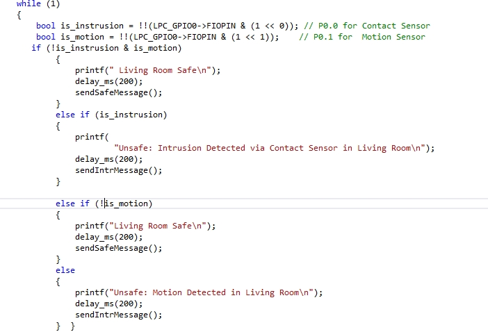
The sensor node is interfaced to a PIR motion sensor and a magnetic contact sensor. The magnetic contact sensor is interfaced to P0.0 and the motion sensor is interfaced to P0.1 of the SJSU micro-controller. Below is an example of how the two pins are set as inputs to get the readings of the two sensors. The inputs from each sensor is stored in the bool variables.
bool is_instrusion = !!(LPC_GPIO0->FIOPIN & (1 << 0));
bool is_motion = !!(LPC_GPIO0->FIOPIN & (1 << 1));
Two bool values are used in an if statement to check the status of individual sensor. If the motion is detected, the statements in if statement are executed and sendIntrMessage() function is called. Similarly if it detects any intrusion via contact sensor, then the statements inside the if else case gets executed. The sendIntrMessage() function establishes communication with the base station via Nordic Wireless and sends an intrusion message. In the sendIntrMessage() function, another function wireless_send() is called, and the parameters passed to that function include address of the base station, message string, string size, and number of hops to base station. Figure 10 shows an an snippet of the function , where the number of hops and address of base station are stored in a char, and then those variables are passed into the function called wireless_send().
Figure 10: Function to send intrusion message to the Base Station
Figure 11: Initialization of GPIO's
Android App
The implementation of the Android App is done using Android SDK ADT Bundle. The bundle is great for new android developers as it contains everything to begin developing apps. The software tools included in the bundle are Eclipse + ADT plug-in, Android SDK Tools, the latest Android platform, the latest Android system image for the emulator.
The implementation of the Android App is mostly done in three files, and those are activity_main.xml, MainActivity.java and AndroidManifest.xml.The activity_main. xml file contains all the code for the user interface and the layout of the Android App. The MainActivity.java file includes all the back-end information for the user interface. It contains the code for the event listeners for the buttons and text-boxes. The third file named AndroidManifest.xml contains all the permissions to use hardware and code.
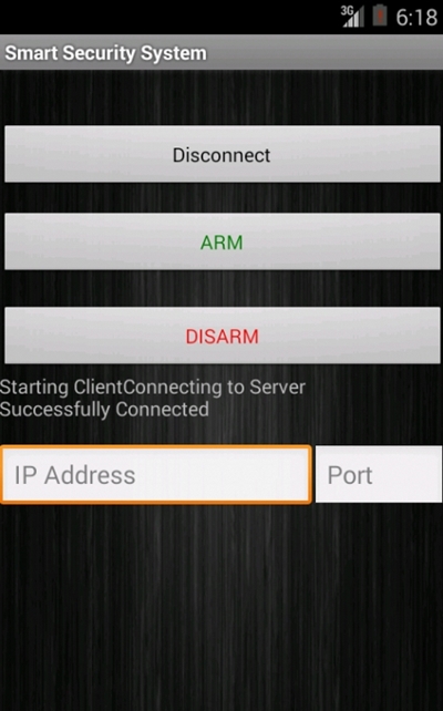
The layout of the app is designed by adding the necessary buttons such as Connect, Arm, and Disarm. Text-boxes to capture user input for IP address and port number are also added to the user interface. This make it very convenient for the user because if the there are any changes to the IP address or the port number of the base station’s Wi-Fi, then nothing in the Android App has to changed. The user can simply type in the new IP address and the port number to establish TCP connection.A single button for Connect and Disconnect is used. Once the connection is established, the name of connection button changes from Connect to Disconnect. To make the application user friendly, the user will get a printed message once the connection is made, and if the connection is not successful an appropriate message will be displayed. For example if the user enters wrong port number, an error message will give the user some indication to correct it. Below is an example of how a button is added to the user interface of the Android App.
Figure 12: Button to User Interface
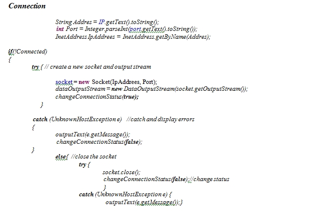
Next an event listener for each button is added in the MainActivity java file. The TCP/IP communication between the Android App and the base station is done using sockets. A new socket gets created when the user enters the port number and IP address.The client then sends a request to the server with dataOutStream. If the connection is successful, the connection status changes to true, else the connection status is changes to false and appropriate exception is printed.The code below shows how a socket is created using the IP address and port number entered by user, and how connection to the server is established.
Figure 13: Event-listener for a Button
Testing & Technical Challenges
Testing Sensor Nodes
Magnetic Contact Sensor and PIR Motion Sensor
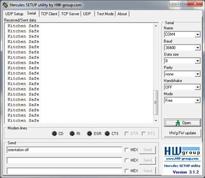
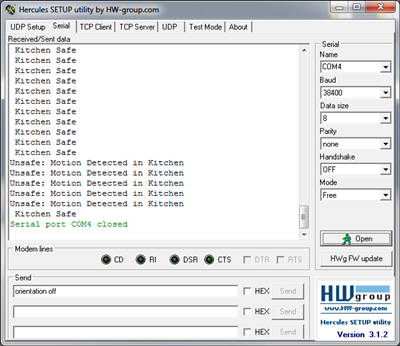
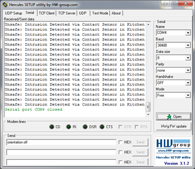
The interface of the sensors with micro-controller was tested using Hercules. To test the sensors, first both sensors were put into a state where they didn't detect any intrusion. The motion sensor was covered with a box, and the magnet switch for the contact sensor was placed next to it to prevent it from sending an intrusion signal. As a result the Hercules screen prints out a “Safe” message. The output seen on Hercules screen is shown in Figure 14. Next the motion sensor is tested by removing the box from the motion sensor. As soon as the box is removed the motion sensor detects activity, and sends a signal to the micro-controller. The micro-controller analyzes the signal and printed a message “Unsafe: Motion Detected in Kitchen”, and the result is shown in the Figure 15. Several trials were done to ensure that the sensor sends the correct signal to the micro-controller every time. Next, the operation of the magnetic contact sensor was tested in a similar way. A box was placed back on the motion sensor to test the operation of just the contact sensor. To test the operation, the magnet is moved away from the reed switch. The contact sensor sends an intrusion signal to the micro-controller. The micro-controller analyzes the signal and prints a message Unsafe: Intrusion Detected via Contact Sensor in Kitchen” and the results are shown in Figure 16.
Figure 14: Safe Status
Figure 15: Motion Detected
Figure 16: Contact Sensor Triggered
Nordic Wireless
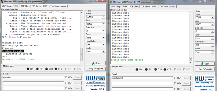
After testing interface of sensors with the micro-controller, the communication between the sensor node and the base station tested was tested. Both the sensor node and the base station were connected to the laptop to display the results on Hercules. The left window shows the output of base station, and the right window shows the output of sensor node. In this scenario, the magnet is moved away from the reed switch and the sensor sends an instruction signal to the sensor node. The sensor node then sends a packet to base station via Nordic wireless, and the message “Instruction detected in the Kitchen” on the base station output screen in Hercules. Another test case was done in order to ensure that correct message was being sent from the sensor node to the base station. In the second scenario, both the sensors send a signal translates to no intrusion as shown in Figure 17. The Hercules window prints a “Kitchen Safe Message”, and the same message is displayed on the Hercules screen for base station.
Figure 17: Left Screen: Base Station, Right Screen: Sensor Node
Testing Base Station
Wi-Fly Module
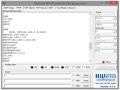
This test will show that the base station has the capability to connect to the internet and take in commands. The wifly module is the component that would establish the connection. Once initialized, it should be connected to the internet by a wireless internet router. Once the connection is made, we would test the connection with Hercules. The IP address is given when the menu popped up is needed when testing. Place the IP address and port number onto the TCP client of Hercules and connect. When we establish a connection, we can send commands to the base station and it should work as it should when we tested it out on the serial port. The results are shown in the Figure 18 below.
Figure 18: Wi-Fly Module Testing
ARM and Disarm States
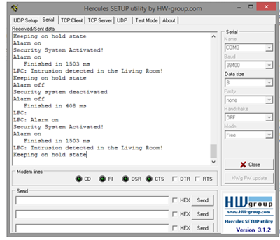
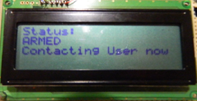
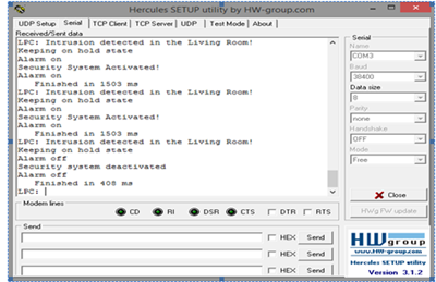
To get the base station into the arm state, the command “Alarm on” will be sent to the base station from the Android App. When it is sent, the base station will search for the packets from the sensor nodes and analyze them for intrusion.The first LED on the LPC1758 board will turn on when the system is armed, and the LCD will display the system status. Disarm state is to turn of the security system. The user can send an command from the Android App to disarm the system. Whenever the disarm command is sent to the base station it will turn on LED 2 on the micro-controller as an indicator, and the status of the security system will update on the LCD screen.
Figure 19: Alarm On Command
Figure 20: Alarm On Command on LCD
Figure 21: Alarm Off Command
MP3 Decoder
The MP3 Decoder is tested by Arming, Disarming, and triggering the security system. At the beginning of test, the security system is disarmed. The motion sensor is covered with a box and the magnet is put close to the contact sensor. Next, the Android App is connected to the Wi-Fly module by entering its IP address and port number. When Arm command is sent from the Android app to the base station, the base station sends a signal to the MP3 decoder, and it plays a sounds indicating system is Armed. Next the box is removed from the motion sensor, and as soon it is removed, the MP3 decoder starts playing alarm sound. The alarm is turned off by pressing the Disarm button from the Android App. When the disarm button is pressed, the MP3 decoder stops playing the alarm sound and plays a different sound indicating the system is disarmed.
Testing Android App
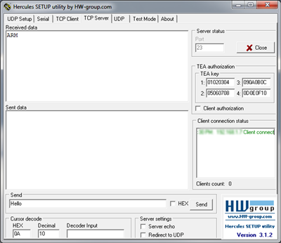
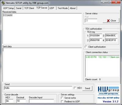
The Android App for the security system is tested twice. First the Android App is tested using Hercules, in this test the Android app act as a client and Hercules acts as a server. This test was done to verify that the commands sent by the Android App are being received the base station. In order to test the client server communication using this method, both the client and server must be connected to the same network. A router was set up to connect both the Android App and laptop running Hercules program to the same network. Next both the Client and Server were connected to the router’s Wi-Fi. In order to establish TCP/IP connection, the Android App need the IP address and the port number of the server. Using ipconfig command in the windows command line the IP address of the server is obtained. Any unused port number for the server can be used. There is one very important thing to remember in the the client server communication, the server must be listening for the connection to be established successfully. To begin the test, a IP address and port number the entered in the Android App. The same port number is set to listening in Hercules. Next, the connect button on the Android App is pressed, and the app establishes a connection with the server as shown in Figure 22. Next, the commands on the Android App are tested. The Arm button on the Android App is pressed, and the command is successfully received by the server as shown in Figure . The disarm command is tested similarly and the result is shown in Figure .
Connection
Figure 22: Connection Established from Android App
Arm and Disarm Commands
Figure 23: Arm Command sent from Android App
Figure 24: Disarm Command sent from Android App
My Issue #1
Android App Manifest File
When testing the Android App, we ran into couple of issues, and one of them was a problem with the Internet Permission. We kept getting java.net.SocketException: Permission denied. This problem was caused because the manifest file was missing an internet permission. The problem was solved by adding the following line of code in the manifest file
<uses-permission android:name="android.permission.INTERNET" />
   <uses-permission android:name="android.permission.ACCESS_NETWORK_STATE"> </uses-permission>
My Issue #2
Android Connection Test Problem
When testing the connection of the Android App (Client) with the Hercules (Server), we were not able to establish the connection successfully. The issue was that we were not setting our server to the listening mode. After spending some time time on the issue, we learned that the server port must be listening before the client tries to establish connection. This was done by going to TCP Server window of Hercules and setting the port to listen mode.
My Issue #3
MP3 Decoder Playing Files
We also faced an issue trying to play MP3 files on the decoder. For some reason the MP3 decoder was not playing the files we wanted it to play. Our intention was to play voice recordings when the security system was armed and disarmed. We record the voice in MP3 format and transferred it to the SD card. The decoder never played the voice recordings, but it did play the alarm sound. After doing lot of trials we learned that the MP3 decoder was playing files of certain bit-rates. To indicate that the system is armed and disarmed, we had to select sounds from files which had bit-rate that the MP3 decoder was able to play.
Conclusion
The project was a very great learning experience. we leaned new things like Android App Development, FreeRTOS, PCB design and also had chance to apply knowledge from previous courses. Although we faced several problems throughout the project, but we learned some important things while solving them. After completing this project we have increased our knowledge of how an operating system works, and how to use various communication protocols such as UART and SPI.
Project Video
Upload a video of your project and post the link here.
Project Source Code
References
Acknowledgement
Preetpal Kang - We are very thankful Professor Preetpal for helping and guiding us throughout the project
Warren Ow - Thankful for his contribution in Designing the Custom Micro-controller Board
Caleb Chow - Thankful for his contributed in Designing the Custom Micro-controller Board
Nathaniel Natividad - for his contribution on the Base Station and Web-server setup
References Used
- [1] Android Application Development Website: [1]
- [2] FreeRTOS website: FreeRTOS Homepage
Appendix
You can list the references you used.
