Difference between revisions of "S14: FaceTime Robo"
Proj user10 (talk | contribs) (→Hardware Interface) |
Proj user10 (talk | contribs) (→Conclusion) |
||
| Line 215: | Line 215: | ||
== Conclusion == | == Conclusion == | ||
| − | + | ||
| + | The FaceTImeRobo was fun project to work on. Through this project, I achieved lot of knowledge about face detection technology. I also learned how to develop windows driver, PWM driver, A/D driver, and GPIO. This project also helped me to learn different ways of testing project, so that it will work flawlessly in real time environment. It was a great experience to write C++ code for ARM Cortex-M3 and later on integrate with real time operating system (FreeRTOS) | ||
| + | |||
| + | If there was more time, I would like to implement the following additions: | ||
| + | |||
| + | * Facial recognition technology so that robot can lock itself to a particular user. | ||
| + | * I wanted to add speaker, so that robot can talk to user. | ||
| + | |||
=== Project Video === | === Project Video === | ||
Revision as of 23:44, 6 May 2014
Contents
Grading Criteria
- How well is Software & Hardware Design described?
- How well can this report be used to reproduce this project?
- Code Quality
- Overall Report Quality:
- Software Block Diagrams
- Hardware Block Diagrams
- Schematic Quality
- Quality of technical challenges and solutions adopted.
Project Title
FaceTime Robo
Abstract
FaceTime Robo (FTB) is a robot which helps in video chat. With the help of FTB, the user can do video chat without holding cell phone in hand. Now user can do multitask, while chatting with their loved ones. FTB works on face detection algorithm.
Objectives & Introduction
FTB has three different modes. The first mode is Normal mode. In normal mode, FTB just tracks user in the room. If user suddenly disappears from FTB range of view, then it would not be able to follow up with user. Therefore, second mode is developed. The second mode is called autonomous search mode. When FTB is set in autonomous search mode, then it keeps searching for user in the room. On finding the user, FTB automatically resumes normal mode. FTB also has voice recognition feature built in. FTB wakes up/sleep on user vocal command. The Third mode is sound localization mode. In this mode, user just calls FTB name and FTB turns into that direction and starts searching for user. The FTB uses It’s artificial intelligence to determine the direction of sound and turns into that direction.
Team Members & Responsibilities
- Team Member
- Himanshu Saini
- Hardware Design
- Driver Development
- Software Design
- Integration and Test
- Project Documentation
- Himanshu Saini
Schedule
| Week# | Date | Task | Actual |
|---|---|---|---|
| 1 | 02/27/2014 | Rough Estimation of parts required in project | Done |
| 2 | 03/06/2014 | Parts Ordered | Done |
| 3 | 03/13/2014 | PWM and ADC Driver | Done |
| 4 | 03/20/2014 | Individual Testing of each parts | Done |
| 5 | 04/03/2014 | Implementation of face recognition algorithm | Done |
| 6 | 04/10/2014 | Windows driver development | Done |
| 7 | 04/17/2014 | Integration of project with RTOS | Done |
| 8 | 04/24/2014 | Sound localization testing | Done |
| 9 | 05/01/2014 | Complete testing of system starts | Done |
Parts List & Cost
The table below summarizes the parts used and the cost for the project.
| Ref Number | Part Number | Description | Qyt | Cost |
|---|---|---|---|---|
| 1 | SJ one Board | SJSU development board, LPC1758 | 1 | $75 |
| 2 | Servos | For Pan/Tilt Mechanism | 2 | $40 |
| 3 | Microphones | For Sound Localization | 2 | $25 |
| 4 | Webcam | Microsoft Webcam | 1 | $25 |
| 5 | Wires | Length: 0.5', 0.3', and 1.00' feet | 25 | $35 |
| 6 | Acrylic sheets | 1 X 1 feet | 1 | $30 |
| 7 | USB to Serial Converter | Converter | 1 | $20 |
| 8 | Other Miscellaneous Stuffs | Stands and Screws | 15 Screws and 8 Stands | $30 |
| 9 | Brackets | For Pan/Tilt | 2 | $10 |
| 10 | Velcro | Size 1 X 1 feet | 1 | $20 |
Design & Implementation
Hardware Design
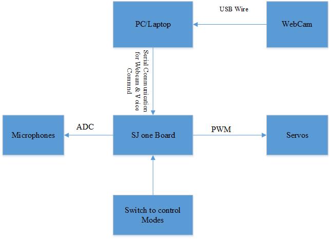
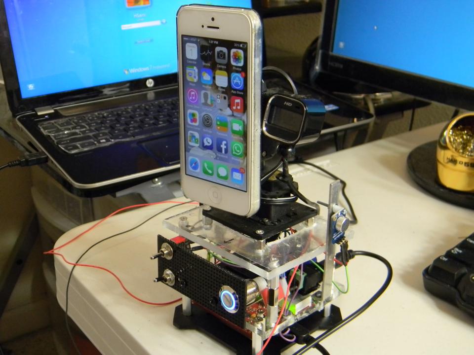
The hardware design of FTB is consists of three layers. The very top layer of FTB has two servo motors, which are placed in such a way so that pan/tilt mechanism can easily be obtained. Bottom servo rotates from left to right. Top servo rotates up and down. The top servo has a bracket attached which has a Velcro on it. The reason of putting Velcro on bracket is to easily place or remove cell phone from FTB. The top layer of FTB also has a camera attach to the bracket. The camera also has inbuilt microphone. There are two more separate microphones on the top layer for sound localization.
The second layer of FTB is consists of breadboards, switches, power supply.
The third layer of FTB is consists of SJ One Board.
Hardware Interface
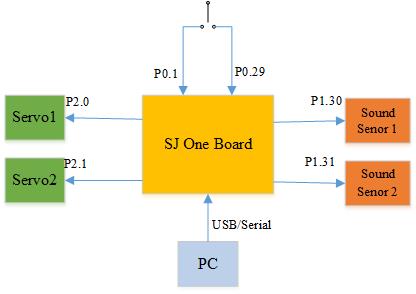
The FTB robot uses following interfaces:
- A/D Converter
- Analog to Digital converter from sound sensors.
- Windows USB to Serial Driver:
- To send the data from PC to SJ One Board.
- Pulse Width Modulation (PWM)
- PWM interface to move servos preciously
- GPIO
- Switches to enable/disable Autonomous Search Mode and Sound Localization Mode
Software Design
The software is divided into two parts. The first part of the software is running at the PC end and the second part of the software is running at the SJ One Board.
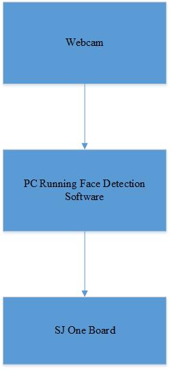
The first part of the software running at the PC requires the face detection algorithm. The software calculates frame per second and the size of the picture frame. On calculating the X and Y axis of the picture frame, the data is send to the SJ One Board.
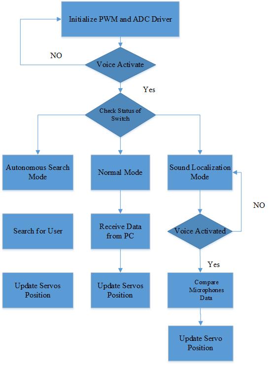
The second part of the software running at SJ One Board requires initialization of PWM and ADC driver. The general flow of software is shown in figure. The software has four tasks. The first task controls “Normal Mode” of the robo. The second task controls “Autonomous Search Mode” of the robo. The third task controls “Voice recognition” of the robo. The fourth and final task controls “Sound Localization Mode” of the robo.
The first task controls “Normal Mode”. As the task begins executing, it waits for the serial data from the PC. On receiving the data from PC, LPC 1758 calculates the values for servos and updates the servos. The second task controls “Autonomous Search mode”. The task two executes when the autonomous search mode switch is turned on. The task two keeps updating servos with new position until unless it finds out the user. The moment tasks two find the user, it automatically switches to “Normal Mode”.
The third task controls voice recognition feature. Whenever the voice command matches to the pre-stored voice commands, then the PC sends data to third task and it takes corresponding actions.
The fourth and final task controls “Sound Localization Mode”. The fourth task executes when the sound localization switch is turned on. The microphone starts receiving data and determines the direction of the sound. Once the direction of the sound detected, the LPC 1758 updates the new position of the servos.
Implementation
This section includes implementation, but again, not the details, just the high level. For example, you can list the steps it takes to communicate over a sensor, or the steps needed to write a page of memory onto SPI Flash. You can include sub-sections for each of your component implementation.
Testing & Technical Challenges
Describe the challenges of your project. What advise would you give yourself or someone else if your project can be started from scratch again? Make a smooth transition to testing section and described what it took to test your project.
Include sub-sections that list out a problem and solution, such as:
My Issue #1
Discuss the issue and resolution.
Conclusion
The FaceTImeRobo was fun project to work on. Through this project, I achieved lot of knowledge about face detection technology. I also learned how to develop windows driver, PWM driver, A/D driver, and GPIO. This project also helped me to learn different ways of testing project, so that it will work flawlessly in real time environment. It was a great experience to write C++ code for ARM Cortex-M3 and later on integrate with real time operating system (FreeRTOS)
If there was more time, I would like to implement the following additions:
- Facial recognition technology so that robot can lock itself to a particular user.
- I wanted to add speaker, so that robot can talk to user.
Project Video
Upload a video of your project and post the link here.
Project Source Code
Send me your zipped source code and I will upload this to SourceForge and link it for you.
References
Acknowledgement
Any acknowledgement that you may wish to provide can be included here.
References Used
List any references used in project.
Appendix
You can list the references you used.
