S14: FaceTime Robo
Contents
Project Title
FaceTime Robo
Abstract
FaceTime Robo (FTB) is a robot which helps in video chat. With the help of FTB, the user can do video chat without holding cell phone in hand. Now user can do multitask, while chatting with their loved ones. FTB works on face detection algorithm.
Objectives & Introduction
FTB has three different modes. The first mode is Normal mode. In normal mode, FTB just tracks user in the room. If user suddenly disappears from FTB range of view, then it would not be able to follow up with user. Therefore, second mode is developed. The second mode is called autonomous search mode. When FTB is set in autonomous search mode, then it keeps searching for user in the room. On finding the user, FTB automatically resumes normal mode. FTB also has voice recognition feature built in. FTB wakes up/sleep on user vocal command. The Third mode is sound localization mode. In this mode, user just calls FTB name and FTB turns into that direction and starts searching for user. The FTB uses It’s artificial intelligence to determine the direction of sound and turns into that direction.
Team Members & Responsibilities
- Team Member
- Himanshu Saini
- Hardware Design
- Driver Development
- Software Design
- Integration and Test
- Project Documentation
- Himanshu Saini
Schedule
| Week# | Date | Task | Actual |
|---|---|---|---|
| 1 | 02/27/2014 | Rough Estimation of parts required in project | Done |
| 2 | 03/06/2014 | Parts Ordered | Done |
| 3 | 03/13/2014 | PWM and ADC Driver | Done |
| 4 | 03/20/2014 | Individual Testing of each parts | Done |
| 5 | 04/03/2014 | Implementation of face recognition algorithm | Done |
| 6 | 04/10/2014 | Windows driver development | Done |
| 7 | 04/17/2014 | Integration of project with RTOS | Done |
| 8 | 04/24/2014 | Sound localization testing | Done |
| 9 | 05/01/2014 | Complete testing of system starts | Done |
Parts List & Cost
The table below summarizes the parts used and the cost for the project.
| Ref Number | Part Number | Description | Qyt | Cost |
|---|---|---|---|---|
| 1 | SJ one Board | SJSU development board, LPC1758 | 1 | $75 |
| 2 | Servos | For Pan/Tilt Mechanism | 2 | $40 |
| 3 | Microphones | For Sound Localization | 2 | $25 |
| 4 | Webcam | Microsoft Webcam | 1 | $25 |
| 5 | Wires | Length: 0.5', 0.3', and 1.00' feet | 25 | $35 |
| 6 | Acrylic sheets | 1 X 1 feet | 1 | $30 |
| 7 | USB to Serial Converter | Converter | 1 | $20 |
| 8 | Other Miscellaneous Stuffs | Stands and Screws | 15 Screws and 8 Stands | $30 |
| 9 | Brackets | For Pan/Tilt | 2 | $10 |
| 10 | Velcro | Size 1 X 1 feet | 1 | $20 |
Design & Implementation
Hardware Design
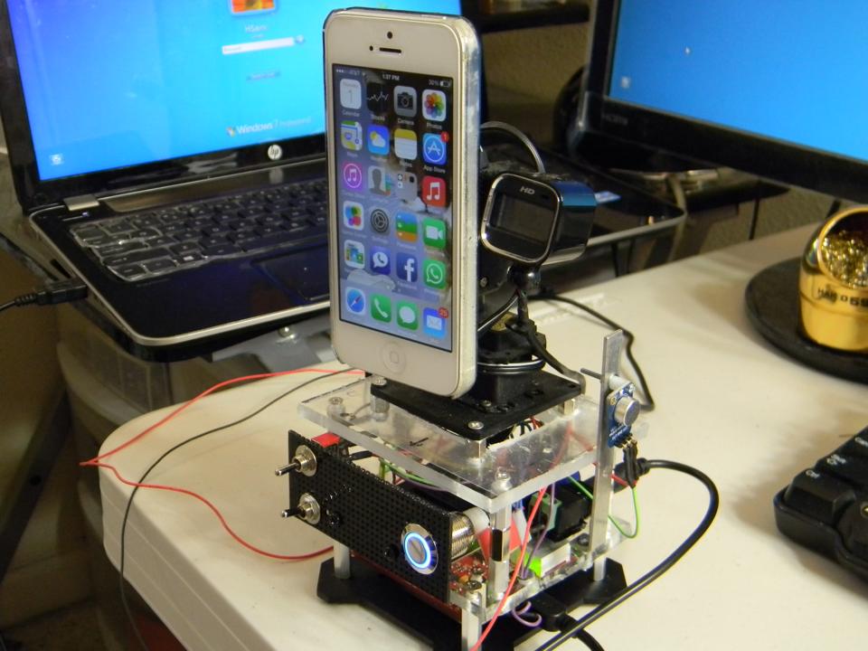
The hardware design of FTB is consists of three layers. The very top layer of FTB has two servo motors, which are placed in such a way so that pan/tilt mechanism can easily be obtained. Bottom servo rotates from left to right. Top servo rotates up and down. The top servo has a bracket attached which has a Velcro on it. The reason of putting Velcro on bracket is to easily place or remove cell phone from FTB. The top layer of FTB also has a camera attach to the bracket. The camera also has inbuilt microphone. There are two more separate microphones on the top layer for sound localization.
The second layer of FTB is consists of breadboards, switches, power supply.
The third layer of FTB is consists of SJ One Board.
Hardware Interface
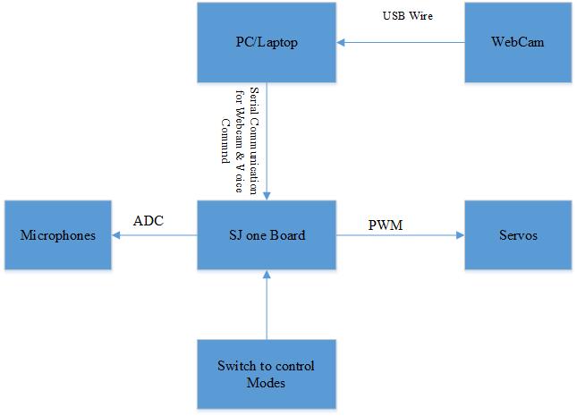
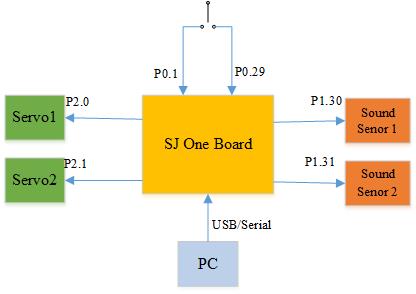
The FTB robot uses following interfaces:
- A/D Converter
- Analog to Digital converter from sound sensors.
- Windows USB to Serial Driver:
- To send the data from PC to SJ One Board.
- Pulse Width Modulation (PWM)
- PWM interface to move servos preciously
- GPIO
- Switches to enable/disable Autonomous Search Mode and Sound Localization Mode
Software Design
The software is divided into two parts. The first part of the software is running at the PC end and the second part of the software is running at the SJ One Board.
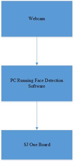
The first part of the software running at the PC requires the face detection algorithm. The software calculates frame per second and the size of the picture frame. On calculating the X and Y axis of the picture frame, the data is send to the SJ One Board.
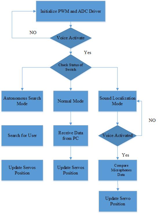
The second part of the software running at SJ One Board requires initialization of PWM and ADC driver. The general flow of software is shown in figure. The software has four tasks. The first task controls “Normal Mode” of the robo. The second task controls “Autonomous Search Mode” of the robo. The third task controls “Voice recognition” of the robo. The fourth and final task controls “Sound Localization Mode” of the robo.
The first task controls “Normal Mode”. As the task begins executing, it waits for the serial data from the PC. On receiving the data from PC, LPC 1758 calculates the values for servos and updates the servos. The second task controls “Autonomous Search mode”. The task two executes when the autonomous search mode switch is turned on. The task two keeps updating servos with new position until unless it finds out the user. The moment tasks two find the user, it automatically switches to “Normal Mode”.
The third task controls voice recognition feature. Whenever the voice command matches to the pre-stored voice commands, then the PC sends data to third task and it takes corresponding actions.
The fourth and final task controls “Sound Localization Mode”. The fourth task executes when the sound localization switch is turned on. The microphone starts receiving data and determines the direction of the sound. Once the direction of the sound detected, the LPC 1758 updates the new position of the servos.
Implementation
Microcontroller to Servo The pulse width modulation driver was written to make the communication between SJ1 board and serovs. When SJ1 board boots up, it initializes PWM driver. Then after, the servo position task keeps updating the position of the servo as instructed by microcontroller.
Microcontroller to Sound Sensors The analog to digital converter driver was written to make the communication between SJ1 board and sound sensors. The sound sensors are analog sensors. When SJ1 boots up, it initializes A/D driver. When “sound localization” mode is selected, then A/D task keeps collecting the data from sound sensors and updates the microcontroller by sensors. Once the sound sensors cross threshold level, then microcontroller compares the reading of all sensors and takes appropriate actions.
Computer to Microcontroller The face detection program running at PC calculates the position of user and sends the data to microcontroller through an interface. The interface is designed using c++. The interface is a windows driver which forwards the data from face detection program to serial COM port. On the other hand, the SJ1 microcontroller receives data through serial communication, UART.
Testing & Technical Challenges
There were several testing and technical challenges, I faced while building this project. There are some challenges which can be avoided very easily by future students, such as
- Have a good soldering iron. It is very important to have a good soldering iron. If wires are not soldered properly, then it would be hard to debug the hardware. Good connections between microcontroller and peripheral will save a lot of hardware debugging time.
- Have a good Oscilloscope. An oscilloscope is very important tool, if you want to build a project like FTB. A good quality of oscilloscope will help you to debug in Pulse Width Modulation. Please do not buy cheap oscilloscope just to save couple hundred dollars. It will help you in a long run.
- Please join a workshop like a “Techshop” to get the right cutting edge tools. If you are a hobbyist and you want to build project from scratch, do not use “Dremel” and other cutting tools at home until unless you are expert. If you do not know how to use cutting tools, then you will waste lot of time and money.
My Issue #1
The biggest issue was designing the system. It took me approx 7 to 10 days to draw the system on paper. If your design has some loop hole, then it would be hard to implement and it will consume your lot of time. For example, I have three layers in my prototype, such as top layer has servos and camera, middle layer has all connections and last layer has SJ1 board. I wanted to design system in such a way that it would be easier to separate layer from each other, if something goes wrong in any layer.
My Issue #2
Another biggest issue was designing interface between computer/laptop to FTB. The interface is responsible to collect the data from laptop and send to SJ1 board. It was a main key of the project. If I would be unable to take out the data from laptop and feed it into SJ1 board, then it would be tough to give life to FTB. Fortunately, I learned windows driver programming in the past. It helped me to design an interface between the computer and SJ1 board.
My Issue #3
The another issue was the huge amount of memory consumption by face detection program running on laptop. Face detection program was consuming memory more than 3GB due to some program errors and then it crashes. Therefore, I increased RAM from 4GB to 12GB. However, the problem was same. The consumption of RAM was still 3GB and then crash. Later on, I found out there was some problem in memory allocation in the program. It took a lot of time to figure out the problem.
Conclusion
The FaceTImeRobo was fun project to work on. Through this project, I achieved lot of knowledge about face detection technology. I also learned how to develop windows driver, PWM driver, A/D driver, and GPIO. This project also helped me to learn different ways of testing project, so that it will work flawlessly in real time environment. It was a great experience to write C++ code for ARM Cortex-M3 and later on integrate with real time operating system (FreeRTOS)
If there was more time, I would like to implement the following additions:
- Facial recognition technology so that robot can lock itself to a particular user.
- I wanted to add speaker, so that robot can talk to user.
Project Video
https://www.youtube.com/watch?v=sDsf6LbdYqA&list=UUmTKr2RNmUsWPyTO_T6kgNg
Project Source Code
References
Acknowledgement
I am very thankful to Professor Preetpal Kang for
- Teaching advance micro-processor.
- Teaching Real Time Operating System (FreeRTOS)
- Helping me in building FaceTime Robo : Darwin
