Difference between revisions of "S14: Data Acquisition using CAN bus"
Proj user9 (talk | contribs) (→Design & Implementation) |
Proj user9 (talk | contribs) (→Hardware Implementation at each NODE) |
||
| Line 237: | Line 237: | ||
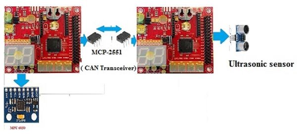
=== Hardware Implementation at each NODE=== | === Hardware Implementation at each NODE=== | ||
| − | [[File:CMPE244_S14_DA_CAN_PinInterface.jpg|200px|thumb|Pin interface on each Node]] | + | [[File:CMPE244_S14_DA_CAN_PinInterface.jpg|200px|thumb|left|Pin interface on each Node]] |
[[File:CMPE244_S14_NODE1.jpg|400px|thumb|left|Node 1]] | [[File:CMPE244_S14_NODE1.jpg|400px|thumb|left|Node 1]] | ||
[[File:CMPE244_S14_NODE2.jpg|400px|thumb|right|Node 2]] | [[File:CMPE244_S14_NODE2.jpg|400px|thumb|right|Node 2]] | ||
| + | [[File:CMPE244_S14_NODE3.jpg|400px|thumb|left|Node 3]] | ||
'''Node 1'''<br /> | '''Node 1'''<br /> | ||
On node 1, we have connected MPU-6050 on I2C2 of SJONE-Board. CAN transceiver is connected on CAN1 of SJONE- board. A terminating resistor is also connected to the CAN transceiver of Node1. <br /> | On node 1, we have connected MPU-6050 on I2C2 of SJONE-Board. CAN transceiver is connected on CAN1 of SJONE- board. A terminating resistor is also connected to the CAN transceiver of Node1. <br /> | ||
| Line 246: | Line 247: | ||
'''Node 3'''<br /> | '''Node 3'''<br /> | ||
| − | + | ||
Revision as of 22:26, 22 May 2014
Contents
Grading Criteria
- How well is Software & Hardware Design described?
- How well can this report be used to reproduce this project?
- Code Quality
- Overall Report Quality:
- Software Block Diagrams
- Hardware Block Diagrams
- Schematic Quality
- Quality of technical challenges and solutions adopted.
Project Title
Abstract
Our project is to implement a high speed data acquisition system using CAN and perform tasks according to the data received. Our system will collect data from sensors over multiple nodes and transmit the data over the CAN bus. The CAN packets are received by a single node which will do the required functionality as desired by the application.The LEDs at the receiver node simulate the functions which ca be done using the data acquired over the CAN bus.The purpose is to gather all the data simultaneously over the CAN bus and implement hardware filtering to manage the data packets on the CAN bus
Figure 1 shows the system block diagram:

Objectives & Introduction
Our idea is to use use 6 degree of freedom MPU-6050 sensor, ultrasonic range finder HC-SR04 as motion/gesture, range signals to control peripherals with the other board via CAN bus. Specific movement/range will trigger predefined tasks and transmit to Android phone via UART-Bluetooth module. More sensors will also be added to do data acquisition.
Team Members & Responsibilities
- Shweta Bohare
- Can bus Interface
- Mradula Nayak
- Can bus Interface
- Heng Zhang
- 6 DOF and sensors
- All Team
- FreeRTOS Software Design
- 3D on the computer
Schedule
Show a simple table or figures that show your scheduled as planned before you started working on the project. Then in another table column, write down the actual schedule so that readers can see the planned vs. actual goals. The point of the schedule is for readers to assess how to pace themselves if they are doing a similar project.
| Week# | Start Date | End Date | Task | Actual |
|---|---|---|---|---|
| 1 | 2/25 | 3/18 |
|
Completed.Other parts are ordered. |
| 2 | 3/18 | 3/26 | Self-Loop testing of CAN Bus | Completed. |
| 4 | 3/27 | 4/13 | Write on microSD SPI microSD I/O | Initial write on SD-card is done. |
| 5 | 4/6 | 4/12 | Interfacing ultrasonic sensor with the board. | Done |
| 6 | 4/13 | 4/27 | Accelerometer data transmission between 2-Boards. | Done |
| 7 | 4/22 | 4/27 | Communication between 3 CAN Nodes | Done |
| 8 | 4/28 | 5/5 | Testing and remove bugs, further enhancements | Done |
| 9 | 5/22 | 5/22 | Demo |
Parts List & Cost
| Parts | Cost | Comment |
|---|---|---|
|
SJ One Board[1] |
$80.00 x3 |
Each board uses for different functions |
GY 521 board(MPU-6050) |
$5.90 x1 |
6 DOF motion sensor |
</tr>
|
TJA1049TK[2] |
$0.00 x4; free samples |
high-speed CAN transceiver |
|
HC-SR04[3] |
$3.00 x1; free samples |
Ultrasonic ranging module |
|
Total Cost |
$249.00 |
Keep it low |
Design & Implementation
Hardware Design and Implementation
In our project we are using three nodes to communicate over a CAN bus. The CAN Controller is embedded on the SJ-ONE board which transmits the microcontroller logic signals to CAN transceiver. The CAN transceiver is a voltage converter which transmits the data on CAN bus by converting it into electrical signals required for CAN. The CAN tranceiver requires a 5V supply for its working. Hence we have designed a Power Circuit to provide 5V dc to the CAN transceiver. In the project, data is acquired from two sensors, each connected to separate nodes. We are using MPU-6050 which is interfaced with Node 1 via I2C protocol. Ultrasonic sensor HC-SR04 is connected to Node 2 which detects the distance of an object from the sensor. The receiver node gets the data from Node 1 and Node 2 and it simulates the data on the LEDs connected.
Description of parts

Power Supply: LM7805
An LM7805 linear regulator IC is used for this purpose. It converts a DC input voltage of range 7-25 V to a stable +5 V. It requires just two external capacitors and is very easy to useThe input DC voltage for LM7805 could be obtained from a 9V DC wall adapter that can supply 1 Amp of load current.We need the 5 volt supply for all the external ICs have been used in this project like MCP2551 and MPU6050.The following schematic is generate the 5Volt regulated power.

CAN transceiver: MCP2551
The MCP2551 is a high-speed CAN, fault-tolerant device that serves as the interface between a CAN protocol controller and the physical bus. The MCP2551 device provides differential transmit and receive capability for the CAN protocol controller, and is fully compatible with the ISO-11898 standard, including 24V requirements. It will operate at speeds of up to 1 Mb/s.
It is used for following functions:
1. As a Transmitter: It operates in two states Dominant and Recessive. When differential voltage between CANH and CANL is less than 102 V it operated in dominant mode, and when the voltage difference is less than 1.2 volt it operates in Recessive mode. These both modes are corresponds to the TXD pin.
2. Maximum nodes: allowing a maximum of 112 nodes to be connected.
3. Receiver Function: The RXD output pin reflects the differential bus voltage between CANH and CANL. The Low and High states of the RXD output pin correspond to the Dominant and Recessive states of the CAN bus, respectively.
4. Operations.High speed flow control and standby. High-Speed mode is selected by connecting the RS pin to VSS. In this mode, the transmitter output drivers have fast output rise and fall times to support high-speed CAN bus rates. The slope, or slew rate (SR), is controlled by connecting an external resistor (REXT) between RS and VOL (usually ground). The device may be placed in Standby or SLEEP mode by applying a high-level to the RS pin.
MCP2551

Motion Sensor: MPU-6050
The MPU-6050 is a motion sensor that combines two chips: the MPU-6050, which contains a 3-axis gyroscope, 3-axis accelerometer and an onboard Digital Motion Processor. Although the built-in processor is integrated with 6-axis MotionFusion algorithms, such as Kalmann filter, it is not open source. As a result, we simply use MPU-6050 as a 6 DOF motion sensor and renders high resolution 6 DOF informations to the SJ-One board for further usage. When developing the MPU driver, we refer to the sparkfun github site: (1. https://github.com/sparkfun/MPU-6050_Breakout; 2. http://www.botched.co.uk/pic-tutorials/mpu6050-setup-data-aquisition/) as well as the given drivers in SJSU-Dev by Professor Preetpal Kang. It is communicate with SJ-One board via I2C ports.

Ultrasonic Sensor: HC-SR04
The Ultrasonic Ranging Module HC-SR04 is a low power simple module, with 4 ports: VCC(5V), GND, Trig(input), Echo(output). It is connected to the SJ-One board through GPIO pins, since it doesn't have protocols. Whenever we need to measure the range, we supply a short 10 us Pulse to the trigger input to invoke this sensor then it will send out 8 cycle burst of ultrasound at 40 kHz so as to receive its echo. The formula to calculate the distance is through the time intervals from trigger signals and the echo signals by: us/58 = centimeters.
Hardware Implementation at each NODE


Node 1
On node 1, we have connected MPU-6050 on I2C2 of SJONE-Board. CAN transceiver is connected on CAN1 of SJONE- board. A terminating resistor is also connected to the CAN transceiver of Node1.
Node 2
On node 2, we have connected HC-SR04 on GPIO pins P1.6 and P1.7. It transmits the distance of the object over the CAN bus. CAN transceiver with terminating resistor is also connected on this node.
Node 3

MPU-6050
#define MPU6050_ADDRESS 0b11010010 // Address with end write bit
#define MPU6050_RA_ACCEL_XOUT_H 0x3B
#define MPU6050_RA_ACCEL_XOUT_L 0x3C
#define MPU6050_RA_ACCEL_YOUT_H 0x3D
#define MPU6050_RA_ACCEL_YOUT_L 0x3E
#define MPU6050_RA_ACCEL_ZOUT_H 0x3F
#define MPU6050_RA_ACCEL_ZOUT_L 0x40
#define MPU6050_RA_TEMP_OUT_H 0x41
#define MPU6050_RA_TEMP_OUT_L 0x42
#define MPU6050_RA_GYRO_XOUT_H 0x43
#define MPU6050_RA_GYRO_XOUT_L 0x44
#define MPU6050_RA_GYRO_YOUT_H 0x45
#define MPU6050_RA_GYRO_YOUT_L 0x46
#define MPU6050_RA_GYRO_ZOUT_H 0x47
#define MPU6050_RA_GYRO_ZOUT_L 0x48
#define MPU6050_RA_WHO_AM_I 0x75
The address of the sensor is set as 0x69 since AD0 is pulled high. The 7 significant bits stores the value and the least significant bit is read/write bit.
The other registers are set to 0 since they are not important in this project.
Before move further, we first need to test the I2C communication between SJ-One and MPU sensor. It is done by this line of code:
I2C2::getInstance().readRegisters(MPU6050_ADDRESS, MPU6050_RA_WHO_AM_I, &Data, 1);
// This is to read the data in MPU6050_RA_WHO_AM_I (0x75) from the MPU through I2C2 readRegisters method,
// if we got 0x68, it indicates the I2C is functioning properly.
After the I2C linking is working, we define a MPU singleton class inherit from I2C2 base:
// Private constructor of this Singleton class
MPU6050_Sensor() : I2C_Base((LPC_I2C_TypeDef*)MPU6050_ADDRESS){}
we implement these methods for MPU class:
bool     MPU6050init();///< Initializes the sensor

uint16_t GYRO_XOUT();  ///< @returns X-Gyro higher value
uint16_t GYRO_YOUT();  ///< @returns Y-Gyro higher value
uint16_t GYRO_ZOUT();  ///< @returns Z-Gyro higher value

uint16_t ACCEL_XOUT(); ///< @returns X-Axis value higher value
uint16_t ACCEL_YOUT(); ///< @returns Y-Axis value higher value
uint16_t ACCEL_ZOUT(); ///< @returns Z-Axis value higher value

unsigned short get16BitRegister(unsigned char reg);
Software Design and Implementation
Show your software design. For example, if you are designing an MP3 Player, show the tasks that you are using, and what they are doing at a high level. Do not show the details of the code. For example, do not show exact code, but you may show psuedocode and fragments of code. Keep in mind that you are showing DESIGN of your software, not the inner workings of it.


Implementation
This section includes implementation, but again, not the details, just the high level. For example, you can list the steps it takes to communicate over a sensor, or the steps needed to write a page of memory onto SPI Flash. You can include sub-sections for each of your component implementation.
Testing & Technical Challenges
Describe the challenges of your project. What advise would you give yourself or someone else if your project can be started from scratch again? Make a smooth transition to testing section and described what it took to test your project.
Include sub-sections that list out a problem and solution, such as:
My Issue #1
Discuss the issue and resolution.
Conclusion
Conclude your project here. You can recap your testing and problems. You should address the "so what" part here to indicate what you ultimately learnt from this project. How has this project increased your knowledge?
Project Video
Upload a video of your project and post the link here.
Project Source Code
Send me your zipped source code and I will upload this to SourceForge and link it for you.
References
Acknowledgement
Any acknowledgement that you may wish to provide can be included here.
References Used
List any references used in project.
Appendix
You can list the references you used.