F16: Autonomous Fire Extinguishing Vehicle
Contents
Grading Criteria
- How well is Software & Hardware Design described?
- How well can this report be used to reproduce this project?
- Code Quality
- Overall Report Quality:
- Software Block Diagrams
- Hardware Block Diagrams
- Schematic Quality
- Quality of technical challenges and solutions adopted.
Autonomous FEV
Abstract
The Autonomous FEV is able to scan a room for fires through a focused IR sensor and navigate to each fire's location. Once the vehicle reaches a reasonable distance from the fire's location, the vehicle will spray water in the fire's general location and extinguish it.
Objectives & Introduction
The objectives of this project include:
- Create a stand-by mode where vehicle would rotate in place and scan
- Have vehicle detect a flame and traverse to its general location
- Stop vehicle when flame is detected and activate water pump to spray in the fire's general location
Team Members & Responsibilities
- Kevin Gadek
- Sensor ADC Interface
- Vehicle Assembly
- Project Documentation
- John Purkis
- DC Motor Controller Interface
- PWM Interface
- Project Documentation
- RuiQiang Yu
- Vehicle Assembly
- Project Documentation
Schedule
| Week# | Start Date | End Data | Task | Status | Actual Completion Date |
|---|---|---|---|---|---|
| 1 | 10/21/2016 | 10/28/2016 | Finalize Project Proposal | Completed | 10/28/2016 |
| 2 | 10/28/2016 | 11/04/2016 | Compile Bill of Materials/Design Schematics | Completed | 11/04/2016 |
| 3 | 11/04/2016 | 11/11/2016 | Order necessary parts | Completed | 11/15/2016 |
| 4 | 11/11/2016 | 11/18/2016 | Disassemble prebuilt RC car/Develop initial IR sensor task | Completed | 11/21/16 |
| 5 | 11/18/2016 | 11/25/2016 | Develop preliminary servo motor control task | Completed | 11/21/16 |
| 6 | 11/25/2016 | 12/2/2016 | Assemble vehicle | Completed | 12/9/2016 |
| 7 | 12/2/2016 | 12/9/2016 | Test/troubleshoot system setup | Completed | 12/11/2016 |
| 8 | 12/9/2016 | 12/16/2016 | Fine-tune/Finalize of project | Completed | 12/18.16 |
| 9 | 12/16/2016 | 12/20/2016 | Prepare for demo/presentation | Completed | 12/20/16 |
Parts List & Cost
| Part Name | Quantity | Cost | Notes |
|---|---|---|---|
| SJOne Board | 1 | $80 | Main microcontroller |
| Infrared Sensor Module | 2 | $13.67 | Placed around front of car to detect and approximate flame location |
| Actobactics Bogie Rover | 1 | $69.99 | Main vehicle |
| Water pump | 1 | $25.77 | Aubig 12V Brushless DC water pump |
| Water pump battery supply | 2 | $8.00 | 12V 8xAA battery pack w/ switch |
| System battery supply | 2 | $5.00 | 6V 4xAA battery pack w/ switch |
| Voltage Regulator | 2 | $2.00 | 5V Voltage Regulator (Approx. 1A output current) |
Design & Implementation
Hardware Design
The overall system design diagram is shown below.

Hardware Interface
SJOne Board
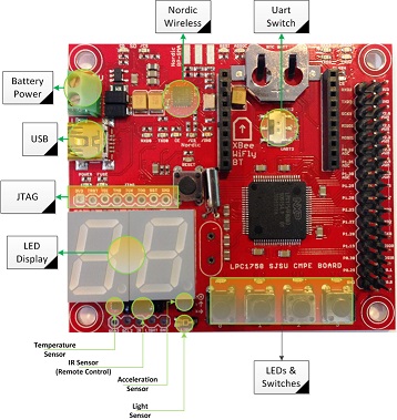
As shown in Figure 3, various pins were selected for the ADC and motor PWM interfaces used in this project.
PWM Control

The H-Bridge Motor Driver is powered by a 12V battery supply that has been regulated down to 5V with an LM7805. This allows both the 4.5V-7.4V voltage requirement of the Bogie Rover to be met while also ensuring enough current is being split among the six motors to adequately drive the Rover. The control signal bank is comprised of +5V, GND, DIR1, PWM1, DIR2 and PWM2 pins that allow motor control with either 3.3V or 5V logic. As shown in Figure 1, two GPIO pins are connected to the two DIR pins to allow easy GPIO switching to change motor direction. Two pins configured for PWM output are connected to the two PWM inputs, allowing for easy motor speed control. The output bank provides for two sets of motor control signals as well as external power input. In order to drive this specific Rover, the LM7805 output is connected to the POWER and GND pins on the driver's output bank, allowing approximately 5V and 2200 mA to be split among all six of the Rover's motors. The two MOTOR1 outputs are connected to the + and - inputs of the three motors on the left side of the Rover and the two MOTOR2 outputs are connected to the right side. This allows easy manipulation of either side of the Rover at once to allow for quick turning and movement.
Software Design
Show your software design. For example, if you are designing an MP3 Player, show the tasks that you are using, and what they are doing at a high level. Do not show the details of the code. For example, do not show exact code, but you may show psuedocode and fragments of code. Keep in mind that you are showing DESIGN of your software, not the inner workings of it.
Implementation
- To implement IR interface
- Configure ADC pin
- Store reading
- Check if reading meets a certain threshold indicating fire detection and change state
- To implement PWM interface
- Configure GPIO and PWM pins
- Depending on which state, either spin in circle, go forward or stop
Testing & Technical Challenges
IR Sensor Calibration
Issue
Calibrating the IR sensor to focus on a specific source of IR waves rather than all the ambient light around it. ADC readings from the IR sensor were sporadic and unpredictable in areas with spotty lighting. Sensitivity calibration ended up not being as helpful as indicated in affecting the analog output of IR sensor.
Solution
This problem was somewhat mitigated by creating a makeshift apparatus with a film canister, forcing the sensor to focus its sensing in one specific direction at a time. The film canister prevents most outside IR waves from interfering with readings.
Motor Power
Issue
Control of the six different DC motors provided on the vehicle was sporadic at best. Because each motor required a peak supply current of approximately 220 mA, the peak output current of the LM7805 voltage regulator often wasn't enough to supply all six of them without either overheating and/or stopping some motors from functioning.
Solution
Attaching a 7805 with a heatsink mitigated many of the overheating issues. Installing a heatsink to the LM7805 instantly resolved power issues and the vehicle was able to traverse ground easily.
Conclusion
This project was ultimately successful at its goal. The RC Rover is able to detect IR light within a reasonable wavelength, detecting both certain flashlights as well as matches. The RC Rover is then able to transition between states according to readings that are being interpreted. These states allow the rover to traverse and navigate to several different fires within an enclosed area. The research done in learning how to interface the SJOne microcontroller over a variety of interfaces like ADC and PWM was a great learning experience. Creating a system with multiple tasks continually context switching and being able to predict the result was also a great lesson on designing with freeRTOS. With further work, this project could be improved both to increase reliability and accuracy.
Project Video
Upload a video of your project and post the link here.
Project Source Code
References
Acknowledgement
Any acknowledgement that you may wish to provide can be included here.
References Used
Appendix
You can list the references you used.