Difference between revisions of "F16: Autonomous Fire Extinguishing Vehicle"
(→Abstract) |
(→Issue) |
||
| (48 intermediate revisions by the same user not shown) | |||
| Line 1: | Line 1: | ||
| − | |||
| − | |||
| − | |||
| − | |||
| − | |||
| − | |||
| − | |||
| − | |||
| − | |||
| − | |||
| − | |||
| − | == | + | |
| + | == Autonomous FEV == | ||
== Abstract == | == Abstract == | ||
| Line 17: | Line 7: | ||
== Objectives & Introduction == | == Objectives & Introduction == | ||
| − | + | The objectives of this project include: | |
| + | * Create a stand-by mode where vehicle would rotate in place and scan | ||
| + | * Have vehicle detect a flame and traverse to its general location | ||
| + | * Stop vehicle when flame is detected and activate water pump to spray in the fire's general location | ||
=== Team Members & Responsibilities === | === Team Members & Responsibilities === | ||
* Kevin Gadek | * Kevin Gadek | ||
| − | ** | + | ** Sensor ADC Interface |
| − | ** | + | ** Vehicle Assembly |
** Project Documentation | ** Project Documentation | ||
* John Purkis | * John Purkis | ||
| − | ** | + | ** DC Motor Controller Interface |
| − | ** | + | ** PWM Interface |
** Project Documentation | ** Project Documentation | ||
* RuiQiang Yu | * RuiQiang Yu | ||
| − | ** | + | ** Vehicle Assembly |
| − | |||
** Project Documentation | ** Project Documentation | ||
== Schedule == | == Schedule == | ||
| − | |||
{| class="wikitable" | {| class="wikitable" | ||
| Line 84: | Line 75: | ||
| 12/2/2016 | | 12/2/2016 | ||
| Assemble vehicle | | Assemble vehicle | ||
| − | | | + | | Completed |
| − | | | + | | 12/9/2016 |
|- | |- | ||
! scope="row"| 7 | ! scope="row"| 7 | ||
| Line 91: | Line 82: | ||
| 12/9/2016 | | 12/9/2016 | ||
| Test/troubleshoot system setup | | Test/troubleshoot system setup | ||
| − | | | + | | Completed |
| − | | | + | | 12/11/2016 |
|- | |- | ||
! scope="row"| 8 | ! scope="row"| 8 | ||
| Line 98: | Line 89: | ||
| 12/16/2016 | | 12/16/2016 | ||
| Fine-tune/Finalize of project | | Fine-tune/Finalize of project | ||
| − | | | + | | Completed |
| − | | | + | | 12/18.16 |
|- | |- | ||
! scope="row"| 9 | ! scope="row"| 9 | ||
| Line 105: | Line 96: | ||
| 12/20/2016 | | 12/20/2016 | ||
| Prepare for demo/presentation | | Prepare for demo/presentation | ||
| − | | | + | | Completed |
| − | | | + | | 12/20/16 |
|} | |} | ||
| Line 123: | Line 114: | ||
|- | |- | ||
! scope="row"| Infrared Sensor Module | ! scope="row"| Infrared Sensor Module | ||
| − | | | + | | 2 |
| $13.67 | | $13.67 | ||
| − | |Placed around front of car to detect flame location | + | |Placed around front of car to detect and approximate flame location |
|- | |- | ||
| − | + | ||
| − | + | ! scope="row"| Actobactics Bogie Rover | |
| − | |||
| − | |||
| − | |||
| − | ! scope="row"| | ||
| 1 | | 1 | ||
| − | | $ | + | | $69.99 |
| Main vehicle | | Main vehicle | ||
|- | |- | ||
| Line 142: | Line 129: | ||
|Aubig 12V Brushless DC water pump | |Aubig 12V Brushless DC water pump | ||
|- | |- | ||
| − | ! scope="row"| | + | ! scope="row"| Water pump battery supply |
| 2 | | 2 | ||
| $8.00 | | $8.00 | ||
|12V 8xAA battery pack w/ switch | |12V 8xAA battery pack w/ switch | ||
| + | |- | ||
| + | ! scope="row"| System battery supply | ||
| + | | 2 | ||
| + | | $5.00 | ||
| + | |6V 4xAA battery pack w/ switch | ||
| + | |- | ||
| + | ! scope="row"| Voltage Regulator | ||
| + | | 2 | ||
| + | | $2.00 | ||
| + | |5V Voltage Regulator (Approx. 1A output current) | ||
|} | |} | ||
== Design & Implementation == | == Design & Implementation == | ||
| − | |||
=== Hardware Design === | === Hardware Design === | ||
| − | + | The overall system design diagram is shown below. | |
| + | [[File: CmpE146 F16 T9 System Diagram.jpg|1000px|thumb|centre|Figure 1. Overall System Diagram]] | ||
=== Hardware Interface === | === Hardware Interface === | ||
| − | + | ==== SJOne Board ==== | |
| + | [[File:sjone_board.jpg|center|frame|link=SJ One Board|Figure 2: SJ-One Board Picture]] | ||
| + | As shown below, various pins from the SJOne Board were selected for the ADC and motor PWM interfaces used in this project. | ||
| + | |||
| + | <center> | ||
| + | '''Pin Connectivity Table''' | ||
| + | |||
| + | {| class="wikitable" | ||
| + | |- | ||
| + | ! scope="col"| Item | ||
| + | ! scope="col"| Port.Pin | ||
| + | ! scope="col"| Direction | ||
| + | ! scope="col"| Notes | ||
| + | |- | ||
| + | ! scope="row"|1 | ||
| + | | P0.26 | ||
| + | | Input | ||
| + | | ADC | ||
| + | |- | ||
| + | ! scope="row"| 2 | ||
| + | | P0.0 | ||
| + | | Output | ||
| + | | DIR1 | ||
| + | |- | ||
| + | ! scope="row"| 3 | ||
| + | | P0.1 | ||
| + | | Output | ||
| + | | DIR2 | ||
| + | |- | ||
| + | ! scope="row"| 4 | ||
| + | | P2.3 | ||
| + | | Output | ||
| + | | PWM1 | ||
| + | |- | ||
| + | ! scope="row"| 5 | ||
| + | | P2.4 | ||
| + | | Input | ||
| + | | PWM2 | ||
| + | |- | ||
| + | ! scope="row"| 6 | ||
| + | | P1.20 | ||
| + | | Output | ||
| + | | Water Pump Enable | ||
| + | |- | ||
| + | |} | ||
| + | </center> | ||
| + | |||
| + | ==== IR ADC Interface ==== | ||
| + | [[File: CmpE146 F16 T9 IR Sensor.jpg|400px|thumb|centre|Figure 3. SmartSense IR Sensor]] | ||
| + | The IR sensor that was used allows both analog as well as digital output readings. For the purposes of this project, as outlined in Figure 1, the analog voltage output of the sensor is tied to an ADC pin in order to allow for much more precise readings. The board's 3.3V output was more than enough to meet the sensor's power requirements. | ||
| + | |||
| + | ==== PWM Control ==== | ||
| + | [[File: CmpE146 F16 T9 Driver.jpg|400px|thumb|centre|Figure 3. IrF3205 H-Bridge Motor Driver]] | ||
| + | |||
| + | The H-Bridge Motor Driver is powered by a 12V battery supply that has been regulated down to 5V with an LM7805. This allows both the 4.5V-7.4V voltage requirement of the Bogie Rover to be met while also ensuring enough current is being split among the six motors to adequately drive the Rover. The control signal bank is comprised of +5V, GND, DIR1, PWM1, DIR2 and PWM2 pins that allow motor control with either 3.3V or 5V logic. As shown in Figure 1, two GPIO pins are connected to the two DIR pins to allow easy GPIO switching to change motor direction. Two pins configured for PWM output are connected to the two PWM inputs, allowing for easy motor speed control. The output bank provides for two sets of motor control signals as well as external power input. In order to drive this specific Rover, the LM7805 output is connected to the POWER and GND pins on the driver's output bank, allowing approximately 5V and 2200 mA to be split among all six of the Rover's motors. The two MOTOR1 outputs are connected to the + and - inputs of the three motors on the left side of the Rover and the two MOTOR2 outputs are connected to the right side. This allows easy manipulation of either side of the Rover at once to allow for quick turning and movement. | ||
| + | |||
| + | ==== Water Pump ==== | ||
| + | [[File:Water_Pump.jpg]] | ||
| + | |||
| + | We used a Aubig 12V Brushless DC water pump for this project. | ||
=== Software Design === | === Software Design === | ||
| − | + | [[File: CmpE146 F16 T9 State Diagram.jpg|400px|thumb|centre|Figure 4. Basic Software State Diagram]] | |
| + | The software logic follows the general flow shown in Figure 4. Various motor control functions are defined such as turn_left, turn_right, go_forward, and reverse that can be called on at will by the several tasks being used. Upon initialization, the state will be set to 0 and the pwm_task will make the Rover rotate in place while a separate flame_task will continually read sensor data. Because the sensor's base value is approximately 4095, conditions are set to check when the readings dip below a certain threshold. In this specific case, readings below 2000 indicate that a flame or flashlight has been detected. The flame_task will then set the system's state to 1 because it now knows that the flame is directly in front of the rover. The rover will then traverse towards the source of the flame while continually reading sensor data. If at any point, the sensor data indicates readings greater than 2000 while the state is still 1, then the system knows that it isn't correctly positioned to face the fire. In this case, the rover will re-enter state 0 and begin searching again. Once during traversal, readings indicate values less than 350, then a reasonable determination can be made that the fire is directly in front of the rover. In this case, all motors will stop and the water pump will start spraying. | ||
| + | === Implementation === | ||
| + | *To implement IR interface | ||
| + | **Configure ADC pin | ||
| + | **Store reading | ||
| + | **Check if reading meets a certain threshold indicating fire detection and change state | ||
| − | + | *To implement PWM interface | |
| − | + | **Configure GPIO and PWM pins | |
| + | **Depending on which state, either spin in circle, go forward or stop | ||
== Testing & Technical Challenges == | == Testing & Technical Challenges == | ||
| − | + | In terms of testing, test runs were conducted in order to fine-tune threshold values so that the Rover is able to detect fires at a reasonable distance. Different lighting environments were used to see how ambient light affected performance and accuracy of the Rover. Overall, the Rover was generally precise in determining a fire's location and stopping at an appropriate distance. Because testing was primarily done with a flashlight because actual fire would be a safety hazard in most cases, different flashlights produced slightly different behaviors from the Rover. | |
| − | + | ||
| + | ==== IR Sensor Calibration ==== | ||
| + | ====== Issue ====== | ||
| + | Calibrating the IR sensor to focus on a specific source of IR waves rather than all the ambient light around it. ADC readings from the IR sensor were sporadic and unpredictable in areas with spotty lighting. Sensitivity calibration ended up not being as helpful as indicated in affecting the analog output of IR sensor. | ||
| + | |||
| + | [[File:CmpE146_F16_T9_FlameSensor.jpg]] | ||
| + | |||
| + | In order to make the sensing element directional it was necessary to block light from all undesired directions. We used a film canister to do this. Film is spoiled if it is exposed to any light. Therefore, film canisters are designed to block light. By placing the sensing element at one end of the film canister we were able to turn a sensing element with no direction into one with direction. | ||
| + | |||
| + | [[File:CmpE146_F16_T9_SensingDirection.jpg]] | ||
| + | |||
| + | The Flame sensing element is used to determine both the direction and distance of a fire. This is because the intensity of a light source is the inverse of the square of its distance. Flames emit visible light and light sources emit light radially. Therefore the greater the intensity of the light and the greater the temperature the closer the vehicle is to the flame. This is used to measure distance. | ||
| + | |||
| + | [[File:CmpE146_F16_T9_RadialLight.jpg]] | ||
| + | |||
| + | Using these settings both distance from the flame and the direction of the flame can be measured. | ||
| + | |||
| + | ====== Solution ====== | ||
| + | This problem was somewhat mitigated by creating a makeshift apparatus with a film canister, forcing the sensor to focus its sensing in one specific direction at a time. The film canister prevents most outside IR waves from interfering with readings. | ||
| + | |||
| + | ==== Motor Power ==== | ||
| + | ===== Issue ===== | ||
| + | Control of the six different DC motors provided on the vehicle was sporadic at best. Because each motor required a peak supply current of approximately 220 mA, the peak output current of the LM7805 voltage regulator often wasn't enough to supply all six of them without either overheating and/or stopping some motors from functioning. | ||
| + | |||
| + | Attaching a 7805 with a heatsink mitigated many of the overheating issues. Installing a heatsink to the LM7805 instantly resolved power issues and the vehicle was able to traverse ground easily. | ||
| + | ==== Water Pump ==== | ||
| + | Originally we were planning on using the H-Bridge MOSFET circuit to drive the water pump that would accompany the fire extinguishing vehicle. The water pump requires 12V DC and is rated for 1.1 Amps of current. This poses a significant problem for a board that can’t supply the power and current required. The solution was to have an electronic switch that can be activated through the use of a GPIO. | ||
| + | ===== Transistor ===== | ||
| + | We planned to use a transistor as an electronic switch. The problem was finding a transistor with a threshold voltage of roughly 3.3 volts which corresponds to the output of a GPIO pin. The transistors we purchased turned out to be insufficient. | ||
| + | ===== Open Drain ===== | ||
| + | Our next solution was to use open drain with an external pull up resistor. By controlling the external voltage and the resistor value we could control the current input and therefore, the speed of the water pump. By modifying the registers PINMODE and PINMODE_OD it is possible to set a given pin to disable its internal pull-up resistor and to enable an open drain configuration. | ||
| − | + | The open drain circuit is shown below. It is essentially the same as the transistor circuit we tried to complete. By making the power source a 12V battery pack and connecting it to an external pull up resistor we were able to briefly control a 12V DC water pump. However, the resistor we were using exploded. | |
| + | Our plan was to connect the water pump to the same 12V DC battery pack that drives the vehicle. It would only be used in S2 when the vehicle decided to stop so it wouldn’t compete with the rest of the vehicle for power. The open drain configuration didn’t work however for unknown reasons. | ||
| − | + | [[File:GPIO_OpenDrain_Fall2016.jpg]] | |
| − | |||
== Conclusion == | == Conclusion == | ||
| − | + | This project was ultimately successful at its goal. The RC Rover is able to detect IR light within a reasonable wavelength, detecting both certain flashlights as well as matches. The RC Rover is then able to transition between states according to readings that are being interpreted. These states allow the rover to traverse and navigate to several different fires within an enclosed area. The research done in learning how to interface the SJOne microcontroller over a variety of interfaces like ADC and PWM was a great learning experience. Creating a system with multiple tasks continually context switching and being able to predict the result was also a great lesson on designing with freeRTOS. With further work, this project could be improved both to increase reliability and accuracy. | |
=== Project Video === | === Project Video === | ||
| − | + | * [https://youtu.be/gImujFzDoJY Demo Run] | |
=== Project Source Code === | === Project Source Code === | ||
| − | * [https:// | + | * [https://github.com/kevin-gadek/146_fev Github Source Code Link] |
== References == | == References == | ||
=== Acknowledgement === | === Acknowledgement === | ||
| − | + | *[https://cmpe.sjsu.edu/profile/preetpal-kang Preetpal Kang] | |
| + | *[https://cmpe.sjsu.edu/profile/haluk-ozemek Haluk Ozemek] | ||
=== References Used === | === References Used === | ||
| − | + | *[http://www.freertos.org/a00106.html FreeRTOS API] | |
| + | *[https://www.fairchildsemi.com/datasheets/LM/LM7805.pdf LM7805 datasheet] | ||
| + | *[https://www.amazon.com/Driver-Module-H-bridge-Mosfet-Irf3205/dp/B00LECI0XC H-Bridge Driver specifications] | ||
| + | *[https://www.amazon.com/Smartsense-Temperature-Compatible-Atomic-Market/dp/B00TNOHTV2/ref=sr_1_13?ie=UTF8&qid=1482305539&sr=8-13&keywords=flame+sensor IR sensor specifications] | ||
| + | *[https://www.servocity.com/bogie Bogie Rover specifications] | ||
=== Appendix === | === Appendix === | ||
You can list the references you used. | You can list the references you used. | ||
Latest revision as of 17:03, 21 December 2016
Contents
Autonomous FEV
Abstract
The Autonomous FEV is able to scan a room for fires through a focused IR sensor and navigate to each fire's location. Once the vehicle reaches a reasonable distance from the fire's location, the vehicle will spray water in the fire's general location and extinguish it.
Objectives & Introduction
The objectives of this project include:
- Create a stand-by mode where vehicle would rotate in place and scan
- Have vehicle detect a flame and traverse to its general location
- Stop vehicle when flame is detected and activate water pump to spray in the fire's general location
Team Members & Responsibilities
- Kevin Gadek
- Sensor ADC Interface
- Vehicle Assembly
- Project Documentation
- John Purkis
- DC Motor Controller Interface
- PWM Interface
- Project Documentation
- RuiQiang Yu
- Vehicle Assembly
- Project Documentation
Schedule
| Week# | Start Date | End Data | Task | Status | Actual Completion Date |
|---|---|---|---|---|---|
| 1 | 10/21/2016 | 10/28/2016 | Finalize Project Proposal | Completed | 10/28/2016 |
| 2 | 10/28/2016 | 11/04/2016 | Compile Bill of Materials/Design Schematics | Completed | 11/04/2016 |
| 3 | 11/04/2016 | 11/11/2016 | Order necessary parts | Completed | 11/15/2016 |
| 4 | 11/11/2016 | 11/18/2016 | Disassemble prebuilt RC car/Develop initial IR sensor task | Completed | 11/21/16 |
| 5 | 11/18/2016 | 11/25/2016 | Develop preliminary servo motor control task | Completed | 11/21/16 |
| 6 | 11/25/2016 | 12/2/2016 | Assemble vehicle | Completed | 12/9/2016 |
| 7 | 12/2/2016 | 12/9/2016 | Test/troubleshoot system setup | Completed | 12/11/2016 |
| 8 | 12/9/2016 | 12/16/2016 | Fine-tune/Finalize of project | Completed | 12/18.16 |
| 9 | 12/16/2016 | 12/20/2016 | Prepare for demo/presentation | Completed | 12/20/16 |
Parts List & Cost
| Part Name | Quantity | Cost | Notes |
|---|---|---|---|
| SJOne Board | 1 | $80 | Main microcontroller |
| Infrared Sensor Module | 2 | $13.67 | Placed around front of car to detect and approximate flame location |
| Actobactics Bogie Rover | 1 | $69.99 | Main vehicle |
| Water pump | 1 | $25.77 | Aubig 12V Brushless DC water pump |
| Water pump battery supply | 2 | $8.00 | 12V 8xAA battery pack w/ switch |
| System battery supply | 2 | $5.00 | 6V 4xAA battery pack w/ switch |
| Voltage Regulator | 2 | $2.00 | 5V Voltage Regulator (Approx. 1A output current) |
Design & Implementation
Hardware Design
The overall system design diagram is shown below.

Hardware Interface
SJOne Board
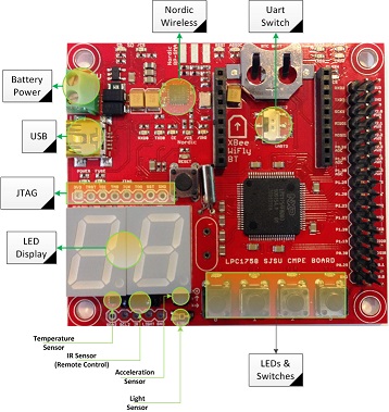
As shown below, various pins from the SJOne Board were selected for the ADC and motor PWM interfaces used in this project.
Pin Connectivity Table
| Item | Port.Pin | Direction | Notes |
|---|---|---|---|
| 1 | P0.26 | Input | ADC |
| 2 | P0.0 | Output | DIR1 |
| 3 | P0.1 | Output | DIR2 |
| 4 | P2.3 | Output | PWM1 |
| 5 | P2.4 | Input | PWM2 |
| 6 | P1.20 | Output | Water Pump Enable |
IR ADC Interface

The IR sensor that was used allows both analog as well as digital output readings. For the purposes of this project, as outlined in Figure 1, the analog voltage output of the sensor is tied to an ADC pin in order to allow for much more precise readings. The board's 3.3V output was more than enough to meet the sensor's power requirements.
PWM Control

The H-Bridge Motor Driver is powered by a 12V battery supply that has been regulated down to 5V with an LM7805. This allows both the 4.5V-7.4V voltage requirement of the Bogie Rover to be met while also ensuring enough current is being split among the six motors to adequately drive the Rover. The control signal bank is comprised of +5V, GND, DIR1, PWM1, DIR2 and PWM2 pins that allow motor control with either 3.3V or 5V logic. As shown in Figure 1, two GPIO pins are connected to the two DIR pins to allow easy GPIO switching to change motor direction. Two pins configured for PWM output are connected to the two PWM inputs, allowing for easy motor speed control. The output bank provides for two sets of motor control signals as well as external power input. In order to drive this specific Rover, the LM7805 output is connected to the POWER and GND pins on the driver's output bank, allowing approximately 5V and 2200 mA to be split among all six of the Rover's motors. The two MOTOR1 outputs are connected to the + and - inputs of the three motors on the left side of the Rover and the two MOTOR2 outputs are connected to the right side. This allows easy manipulation of either side of the Rover at once to allow for quick turning and movement.
Water Pump
We used a Aubig 12V Brushless DC water pump for this project.
Software Design

The software logic follows the general flow shown in Figure 4. Various motor control functions are defined such as turn_left, turn_right, go_forward, and reverse that can be called on at will by the several tasks being used. Upon initialization, the state will be set to 0 and the pwm_task will make the Rover rotate in place while a separate flame_task will continually read sensor data. Because the sensor's base value is approximately 4095, conditions are set to check when the readings dip below a certain threshold. In this specific case, readings below 2000 indicate that a flame or flashlight has been detected. The flame_task will then set the system's state to 1 because it now knows that the flame is directly in front of the rover. The rover will then traverse towards the source of the flame while continually reading sensor data. If at any point, the sensor data indicates readings greater than 2000 while the state is still 1, then the system knows that it isn't correctly positioned to face the fire. In this case, the rover will re-enter state 0 and begin searching again. Once during traversal, readings indicate values less than 350, then a reasonable determination can be made that the fire is directly in front of the rover. In this case, all motors will stop and the water pump will start spraying.
Implementation
- To implement IR interface
- Configure ADC pin
- Store reading
- Check if reading meets a certain threshold indicating fire detection and change state
- To implement PWM interface
- Configure GPIO and PWM pins
- Depending on which state, either spin in circle, go forward or stop
Testing & Technical Challenges
In terms of testing, test runs were conducted in order to fine-tune threshold values so that the Rover is able to detect fires at a reasonable distance. Different lighting environments were used to see how ambient light affected performance and accuracy of the Rover. Overall, the Rover was generally precise in determining a fire's location and stopping at an appropriate distance. Because testing was primarily done with a flashlight because actual fire would be a safety hazard in most cases, different flashlights produced slightly different behaviors from the Rover.
IR Sensor Calibration
Issue
Calibrating the IR sensor to focus on a specific source of IR waves rather than all the ambient light around it. ADC readings from the IR sensor were sporadic and unpredictable in areas with spotty lighting. Sensitivity calibration ended up not being as helpful as indicated in affecting the analog output of IR sensor.

In order to make the sensing element directional it was necessary to block light from all undesired directions. We used a film canister to do this. Film is spoiled if it is exposed to any light. Therefore, film canisters are designed to block light. By placing the sensing element at one end of the film canister we were able to turn a sensing element with no direction into one with direction.

The Flame sensing element is used to determine both the direction and distance of a fire. This is because the intensity of a light source is the inverse of the square of its distance. Flames emit visible light and light sources emit light radially. Therefore the greater the intensity of the light and the greater the temperature the closer the vehicle is to the flame. This is used to measure distance.

Using these settings both distance from the flame and the direction of the flame can be measured.
Solution
This problem was somewhat mitigated by creating a makeshift apparatus with a film canister, forcing the sensor to focus its sensing in one specific direction at a time. The film canister prevents most outside IR waves from interfering with readings.
Motor Power
Issue
Control of the six different DC motors provided on the vehicle was sporadic at best. Because each motor required a peak supply current of approximately 220 mA, the peak output current of the LM7805 voltage regulator often wasn't enough to supply all six of them without either overheating and/or stopping some motors from functioning.
Attaching a 7805 with a heatsink mitigated many of the overheating issues. Installing a heatsink to the LM7805 instantly resolved power issues and the vehicle was able to traverse ground easily.
Water Pump
Originally we were planning on using the H-Bridge MOSFET circuit to drive the water pump that would accompany the fire extinguishing vehicle. The water pump requires 12V DC and is rated for 1.1 Amps of current. This poses a significant problem for a board that can’t supply the power and current required. The solution was to have an electronic switch that can be activated through the use of a GPIO.
Transistor
We planned to use a transistor as an electronic switch. The problem was finding a transistor with a threshold voltage of roughly 3.3 volts which corresponds to the output of a GPIO pin. The transistors we purchased turned out to be insufficient.
Open Drain
Our next solution was to use open drain with an external pull up resistor. By controlling the external voltage and the resistor value we could control the current input and therefore, the speed of the water pump. By modifying the registers PINMODE and PINMODE_OD it is possible to set a given pin to disable its internal pull-up resistor and to enable an open drain configuration.
The open drain circuit is shown below. It is essentially the same as the transistor circuit we tried to complete. By making the power source a 12V battery pack and connecting it to an external pull up resistor we were able to briefly control a 12V DC water pump. However, the resistor we were using exploded. Our plan was to connect the water pump to the same 12V DC battery pack that drives the vehicle. It would only be used in S2 when the vehicle decided to stop so it wouldn’t compete with the rest of the vehicle for power. The open drain configuration didn’t work however for unknown reasons.
File:GPIO OpenDrain Fall2016.jpg
Conclusion
This project was ultimately successful at its goal. The RC Rover is able to detect IR light within a reasonable wavelength, detecting both certain flashlights as well as matches. The RC Rover is then able to transition between states according to readings that are being interpreted. These states allow the rover to traverse and navigate to several different fires within an enclosed area. The research done in learning how to interface the SJOne microcontroller over a variety of interfaces like ADC and PWM was a great learning experience. Creating a system with multiple tasks continually context switching and being able to predict the result was also a great lesson on designing with freeRTOS. With further work, this project could be improved both to increase reliability and accuracy.
Project Video
Project Source Code
References
Acknowledgement
References Used
- FreeRTOS API
- LM7805 datasheet
- H-Bridge Driver specifications
- IR sensor specifications
- Bogie Rover specifications
Appendix
You can list the references you used.