Difference between revisions of "F14: Self Driving Undergrad Team"
Proj user8 (talk | contribs) (→Geographical Controller Team Hardware Design) |
Proj user8 (talk | contribs) (→Grading Criteria) |
||
| (274 intermediate revisions by 2 users not shown) | |||
| Line 1: | Line 1: | ||
| − | == | + | == Chi Lam == |
| − | <font | + | <center> |
| − | + | <font size="5"> '''In Memory of Chi Lam''' </font><br><br> | |
| − | + | <font size="4">June 7th, 1991 - October 27th, 2014 <br> <br> | |
| − | + | [[File:CmpE243_F14_TeamUndergrad_InMemoryofChiLam.jpg|700px]]<br> <br> | |
| − | + | This project is dedicated to Chi Lam, a beloved friend, dedicated Computer Engineering student, and member of this team. <br> <br> | |
| − | |||
| − | |||
| − | |||
| − | |||
| − | < | ||
| − | + | You will be missed, friend | |
| − | + | </font></center> | |
| − | |||
| − | |||
| − | |||
| − | You will be missed, friend | ||
== Self-Driving Autonomous Car == | == Self-Driving Autonomous Car == | ||
| Line 24: | Line 15: | ||
== Objectives & Introduction == | == Objectives & Introduction == | ||
| − | |||
| − | [[File:CmpE243_F14_TUndergrad_HighLevelDiagram.jpg]] | + | |
| + | <br> | ||
| + | [[File:CmpE243_F14_TUndergrad_HighLevelDiagram.jpg|700px|centre|thumb|Overall System Communication Diagram]] | ||
| + | |||
| + | |||
=== Team Members & Responsibilities === | === Team Members & Responsibilities === | ||
| + | |||
| + | The team consisted of 15 undergraduate students taking a graduate level course, thus competing against the Master's level students. <br> | ||
| + | <H1> | ||
| + | We are <br> | ||
| + | |||
| + | [[File:CmpE243_F14_TeamUndergrad_TULogo.jpg|700px]] | ||
| + | |||
| + | </H1> | ||
{| class="wikitable" | {| class="wikitable" | ||
| Line 41: | Line 43: | ||
|- | |- | ||
| - Overall vehicle logic<br/>- Overall software vehicle Integration<br/>- CAN TX/RX messages architecture | | - Overall vehicle logic<br/>- Overall software vehicle Integration<br/>- CAN TX/RX messages architecture | ||
| − | | - Vehicle hardware<br/>- Assistant to other teams<br/>- Module specific logic | + | | - Vehicle hardware interfacing<br/>- Assistant to other teams<br/>- Module specific logic |
| − | | - Module specific logic<br/>- CAN RX processing | + | | - Module specific logic<br/>- CAN RX processing<br/>- GPS waypoint logic |
|- | |- | ||
|} | |} | ||
| Line 67: | Line 69: | ||
! Wei-chieh "Andy" Lo | ! Wei-chieh "Andy" Lo | ||
|- | |- | ||
| − | | - | + | | - Vehicle hardware<br/>- Sensor implementation<br/>- CAN communication |
| − | | - | + | | - Sensor implementation<br/>- Sensor values verification <br/>- CAN communication |
|- | |- | ||
|} | |} | ||
| Line 82: | Line 84: | ||
! Albert Chen | ! Albert Chen | ||
|- | |- | ||
| − | | - Compass calibration/integration | + | | - Compass calibration/integration & structure modelling |
| − | | - GPS testing/integration | + | | - GPS testing/integration & structure modelling |
| - CAN communication | | - CAN communication | ||
|- | |- | ||
| Line 118: | Line 120: | ||
== Schedule == | == Schedule == | ||
| − | |||
| − | |||
'''Final Product Schedule''' | '''Final Product Schedule''' | ||
| Line 147: | Line 147: | ||
| 11/7 | | 11/7 | ||
| Basic Vehicle Self-Driving Test | | Basic Vehicle Self-Driving Test | ||
| − | | | + | | Complete |
|- | |- | ||
! scope="row"| 5 | ! scope="row"| 5 | ||
| 11/14 | | 11/14 | ||
| P2P testing and improved obstacle avoidance | | P2P testing and improved obstacle avoidance | ||
| − | | | + | | Complete |
|- | |- | ||
! scope="row"| 6 | ! scope="row"| 6 | ||
| 11/31 | | 11/31 | ||
| Buffer time for previous tasks and increased vehicle speed | | Buffer time for previous tasks and increased vehicle speed | ||
| − | | | + | | Complete |
|} | |} | ||
| Line 171: | Line 171: | ||
| 10/13 | | 10/13 | ||
| Sensor Input Distance Calibration | | Sensor Input Distance Calibration | ||
| − | | Incomplete: | + | | Incomplete: Need sensor value "filtering" logic. (Completed ~12/2) |
|- | |- | ||
! scope="row"| 2 | ! scope="row"| 2 | ||
| Line 196: | Line 196: | ||
| 11/1 | | 11/1 | ||
| Implement diagnostic LED patterns | | Implement diagnostic LED patterns | ||
| − | | | + | | Completed. |
|- | |- | ||
! scope="row"| 7 | ! scope="row"| 7 | ||
| Line 210: | Line 210: | ||
! scope="row"| 9 | ! scope="row"| 9 | ||
| 11/10 | | 11/10 | ||
| − | | | + | | Eliminate outliers (software) |
| − | | | + | | Completed. |
|- | |- | ||
! scope="row"| 10 | ! scope="row"| 10 | ||
| 11/13 | | 11/13 | ||
| − | | | + | | Eliminate outliers by strengthening sensor wiring (hardware) |
| − | + | | Completed. | |
| − | |||
| − | |||
| − | |||
| − | |||
| − | | | ||
|- | |- | ||
! scope="row"| 12 | ! scope="row"| 12 | ||
| 11/24 | | 11/24 | ||
| Continue testing and tuning as necessary | | Continue testing and tuning as necessary | ||
| − | | | + | | Completed. |
|} | |} | ||
| Line 256: | Line 251: | ||
| 11/2 | | 11/2 | ||
| Improve fine motor movements with master/sensor teams | | Improve fine motor movements with master/sensor teams | ||
| − | | | + | | Incomplete, still needs tweaking. |
|- | |- | ||
! scope="row"| 5 | ! scope="row"| 5 | ||
| 11/9 | | 11/9 | ||
| Once wheel encoder comes in, learn/test/implement onto car | | Once wheel encoder comes in, learn/test/implement onto car | ||
| − | | | + | | Incomplete, wheel encoder cannot be implemented, scrapping. |
|- | |- | ||
! scope="row"| 6 | ! scope="row"| 6 | ||
| 11/16 | | 11/16 | ||
| Integrate wheel encoder with rest of car | | Integrate wheel encoder with rest of car | ||
| − | | | + | | Incomplete, scrapped wheel encoder. |
|- | |- | ||
! scope="row"| 7 | ! scope="row"| 7 | ||
| 11/23 | | 11/23 | ||
| Test for proper operation | | Test for proper operation | ||
| − | | | + | | Complete, added functionality for center steer and forward speed calibration. |
|- | |- | ||
! scope="row"| 8 | ! scope="row"| 8 | ||
| 11/30 | | 11/30 | ||
| Continue testing until proper operation | | Continue testing until proper operation | ||
| − | | | + | | Complete, motor works as intended. |
|- | |- | ||
|} | |} | ||
| Line 330: | Line 325: | ||
| 10/25 | | 10/25 | ||
| Implement onto Final Product | | Implement onto Final Product | ||
| − | | | + | | Complete (Completed on 11/23/2014) |
|- | |- | ||
! scope="row"| 7 | ! scope="row"| 7 | ||
| 11/2 | | 11/2 | ||
| Headlights for car (hardware and software) + Aesthetics for GUI + Clean up code | | Headlights for car (hardware and software) + Aesthetics for GUI + Clean up code | ||
| − | | | + | | Complete (Completed on 12/01/2014) *NOTE Headlights are lost in hardware land |
|} | |} | ||
| Line 349: | Line 344: | ||
| 10/13 | | 10/13 | ||
| CAN Network Test | | CAN Network Test | ||
| − | | Complete | + | | Complete. |
|- | |- | ||
! scope="row"| 2 | ! scope="row"| 2 | ||
| 10/20 | | 10/20 | ||
| Interface Bluetooth Module with CAN | | Interface Bluetooth Module with CAN | ||
| − | | Complete | + | | Complete. |
|- | |- | ||
! scope="row"| 3 | ! scope="row"| 3 | ||
| 10/27 | | 10/27 | ||
| Mount PCB on car | | Mount PCB on car | ||
| − | | | + | | Complete. |
|- | |- | ||
! scope="row"| 4 | ! scope="row"| 4 | ||
| 11/3 | | 11/3 | ||
| Create basic Android application | | Create basic Android application | ||
| − | | | + | | Complete (completed ~10/18). |
|- | |- | ||
! scope="row"| 5 | ! scope="row"| 5 | ||
| 11/10 | | 11/10 | ||
| Add map onto the Android application | | Add map onto the Android application | ||
| − | | | + | | Complete (completed ~10/25). |
|- | |- | ||
! scope="row"| 6 | ! scope="row"| 6 | ||
| 11/17 | | 11/17 | ||
| Send/receive CAN Messages via Android Application | | Send/receive CAN Messages via Android Application | ||
| − | | | + | | Complete (sending completed ~10/18, receiving ~11/1). |
|- | |- | ||
! scope="row"| 7 | ! scope="row"| 7 | ||
| 11/24 | | 11/24 | ||
| Debug and Optimize Android Application | | Debug and Optimize Android Application | ||
| − | | | + | | Complete. |
|- | |- | ||
! scope="row"| 8 | ! scope="row"| 8 | ||
| 12/1 | | 12/1 | ||
| Continue Debugging and Optimizing as Necessary | | Continue Debugging and Optimizing as Necessary | ||
| − | | | + | | Complete. |
|} | |} | ||
| Line 398: | Line 393: | ||
| 10/8 | | 10/8 | ||
| Interface with GPS/Compass | | Interface with GPS/Compass | ||
| − | | | + | | Complete - receiving values |
|- | |- | ||
! scope="row"| 2 | ! scope="row"| 2 | ||
| 10/15 | | 10/15 | ||
| Finish core API | | Finish core API | ||
| − | | | + | | Complete |
|- | |- | ||
! scope="row"| 3 | ! scope="row"| 3 | ||
| 10/22 | | 10/22 | ||
| GPS get fix and receive raw data | | GPS get fix and receive raw data | ||
| − | | | + | | Complete - raw data received, but need faster fix |
|- | |- | ||
! scope="row"| 4 | ! scope="row"| 4 | ||
| 10/22 | | 10/22 | ||
| Compass determine heading | | Compass determine heading | ||
| − | | | + | | Complete - heading may require additional calibration |
|- | |- | ||
! scope="row"| 5 | ! scope="row"| 5 | ||
| 10/29 | | 10/29 | ||
| − | | | + | | Implement calibration algorithm |
| − | | | + | | Complete |
|- | |- | ||
! scope="row"| 6 | ! scope="row"| 6 | ||
| 10/29 | | 10/29 | ||
| GPS parse raw data to extract needed data | | GPS parse raw data to extract needed data | ||
| − | | | + | | Complete - returns latitude, longitude, and calculated heading |
|- | |- | ||
! scope="row"| 7 | ! scope="row"| 7 | ||
| 10/29 | | 10/29 | ||
| Compass use heading from GPS to improve accuracy | | Compass use heading from GPS to improve accuracy | ||
| − | | | + | | N/A - Decided that magnetometer provides accurate enough reading |
|- | |- | ||
! scope="row"| 8 | ! scope="row"| 8 | ||
| 11/5 | | 11/5 | ||
| Improve GPS satellite procurement (antennae?) | | Improve GPS satellite procurement (antennae?) | ||
| − | | | + | | Complete - attached antennae to GPS unit |
|- | |- | ||
! scope="row"| 9 | ! scope="row"| 9 | ||
| 11/12 | | 11/12 | ||
| Improve boot up time of GPS module via warm start | | Improve boot up time of GPS module via warm start | ||
| − | | | + | | N/A - EZ start fast fix mode cannot coincide with 10 Hz update rate (defaults down to 1 Hz) |
|- | |- | ||
! scope="row"| 10 | ! scope="row"| 10 | ||
| 11/12 | | 11/12 | ||
| Fine tune compass calibration technique for accuracy | | Fine tune compass calibration technique for accuracy | ||
| − | | | + | | Complete - Compass still about 20 degrees off, but well within usable margins. Offset likely due to nearby power source on car. |
|- | |- | ||
| − | ! scope="row"| | + | ! scope="row"| 11 |
| 12/3 | | 12/3 | ||
| Buffer time for completion of previous tasks | | Buffer time for completion of previous tasks | ||
| − | | | + | | Complete |
|} | |} | ||
| − | |||
'''Master Controller Schedule''' | '''Master Controller Schedule''' | ||
| Line 463: | Line 457: | ||
| 10/15/14 | | 10/15/14 | ||
| Decide on raw CAN struct architecture | | Decide on raw CAN struct architecture | ||
| − | | Early | + | | Early Completion |
|- | |- | ||
! scope="row"| 2 | ! scope="row"| 2 | ||
| 10/18/14 | | 10/18/14 | ||
| Develop and layout general common CAN messages | | Develop and layout general common CAN messages | ||
| − | | On-time | + | | On-time Completion |
|- | |- | ||
! scope="row"| 3 | ! scope="row"| 3 | ||
| 10/20/14 | | 10/20/14 | ||
| Design vehicle initialization procedure | | Design vehicle initialization procedure | ||
| − | | Early | + | | Early Completion |
|- | |- | ||
! scope="row"| 4 | ! scope="row"| 4 | ||
| 10/23/14 | | 10/23/14 | ||
| Develop and layout Inter-Controller Communication - Each Module's CAN messages | | Develop and layout Inter-Controller Communication - Each Module's CAN messages | ||
| − | | Early | + | | Early Completion |
|- | |- | ||
! scope="row"| 5 | ! scope="row"| 5 | ||
| 10/25/14 | | 10/25/14 | ||
| Design vehicle initial running freed drive mode procedure - Controlled via Phone, no object detection and avoidance, no GPS, no Heading | | Design vehicle initial running freed drive mode procedure - Controlled via Phone, no object detection and avoidance, no GPS, no Heading | ||
| − | | Early | + | | Early Completion |
|- | |- | ||
! scope="row"| 6 | ! scope="row"| 6 | ||
| 10/28/14 | | 10/28/14 | ||
| Complete design on vehicle running free drive mode procedure | | Complete design on vehicle running free drive mode procedure | ||
| − | | On-time | + | | On-time Completion |
|- | |- | ||
! scope="row"| 7 | ! scope="row"| 7 | ||
| 10/30/14 | | 10/30/14 | ||
| Design vehicle initial running indoor drive mode procedure - Timed autonomous drive , object detection and avoidance, (possibly heading), and no GPS | | Design vehicle initial running indoor drive mode procedure - Timed autonomous drive , object detection and avoidance, (possibly heading), and no GPS | ||
| − | | | + | | Late Completion |
|- | |- | ||
! scope="row"| 8 | ! scope="row"| 8 | ||
| Line 503: | Line 497: | ||
| 11/02/14 | | 11/02/14 | ||
| Design vehicle initial running gps drive mode procedure - Full autonomous drive , object detection and avoidance, heading and GPS | | Design vehicle initial running gps drive mode procedure - Full autonomous drive , object detection and avoidance, heading and GPS | ||
| − | | | + | | Late Completion |
|- | |- | ||
! scope="row"| 10 | ! scope="row"| 10 | ||
| 11/05/14 | | 11/05/14 | ||
| All CAN message receive processing complete | | All CAN message receive processing complete | ||
| − | | On-time | + | | On-time Completion |
|- | |- | ||
! scope="row"| 11 | ! scope="row"| 11 | ||
| 11/14/14 | | 11/14/14 | ||
| All basic vehicle functionality state machines implemented and verified | | All basic vehicle functionality state machines implemented and verified | ||
| − | | On-time | + | | On-time Completion |
|- | |- | ||
! scope="row"| 12 | ! scope="row"| 12 | ||
| 11/15/14 | | 11/15/14 | ||
| Complete design on vehicle running indoor drive mode procedure | | Complete design on vehicle running indoor drive mode procedure | ||
| − | | | + | | Late Completion |
|- | |- | ||
! scope="row"| 13 | ! scope="row"| 13 | ||
| 11/20/14 | | 11/20/14 | ||
| Complete design on vehicle running gps drive mode procedure | | Complete design on vehicle running gps drive mode procedure | ||
| − | | | + | | Late Completion |
|- | |- | ||
! scope="row"| 14 | ! scope="row"| 14 | ||
| 11/30/14 | | 11/30/14 | ||
| Any additional advanced functionality implemented and verified | | Any additional advanced functionality implemented and verified | ||
| − | | | + | | Late Completion |
|- | |- | ||
|} | |} | ||
| Line 575: | Line 569: | ||
|- | |- | ||
! scope="row"| 5 | ! scope="row"| 5 | ||
| + | | GPS Antenna - External Active Antenna - 3-5V 28dB 5 Meter SMA | ||
| + | | Adafruit | ||
| + | | 960 | ||
| + | | 1 | ||
| + | | 12.95 + (4.735 Shipping) | ||
| + | |- | ||
| + | |- | ||
| + | ! scope="row"| 6 | ||
| + | | SMA to uFL/u.FL/IPX/IPEX RF Adapter Cable | ||
| + | | Adafruit | ||
| + | | 851 | ||
| + | | 1 | ||
| + | | 3.95 + (4.735 Shipping) | ||
| + | |- | ||
| + | |- | ||
| + | ! scope="row"| 7 | ||
| 3.5" Intelligent module w/ Touch | | 3.5" Intelligent module w/ Touch | ||
| 4D Systems | | 4D Systems | ||
| Line 582: | Line 592: | ||
|- | |- | ||
|- | |- | ||
| − | ! scope="row"| | + | ! scope="row"| 8 |
| 2GB microSD Card | | 2GB microSD Card | ||
| | | | ||
| Line 590: | Line 600: | ||
|- | |- | ||
|- | |- | ||
| − | ! scope="row"| | + | ! scope="row"| 9 |
| uUSB-PA5 Programming Adaptor | | uUSB-PA5 Programming Adaptor | ||
| | | | ||
| Line 598: | Line 608: | ||
|- | |- | ||
|- | |- | ||
| − | ! scope="row"| | + | ! scope="row"| 10 |
| 150mm 5 way Female-Female jumper cable | | 150mm 5 way Female-Female jumper cable | ||
| | | | ||
| Line 606: | Line 616: | ||
|- | |- | ||
|- | |- | ||
| − | ! scope="row"| | + | ! scope="row"| 11 |
| 5 way Male-Male adaptor | | 5 way Male-Male adaptor | ||
| | | | ||
| Line 614: | Line 624: | ||
|- | |- | ||
|- | |- | ||
| − | ! scope="row"| | + | ! scope="row"| 12 |
| Sharp Infrared Range Finder | | Sharp Infrared Range Finder | ||
| 4D Systems | | 4D Systems | ||
| Line 622: | Line 632: | ||
|- | |- | ||
|- | |- | ||
| − | ! scope="row"| | + | ! scope="row"| 13 |
| SainSmart Sonar Ranging Detector | | SainSmart Sonar Ranging Detector | ||
| Amazon | | Amazon | ||
| Line 630: | Line 640: | ||
|- | |- | ||
|- | |- | ||
| − | ! scope="row"| | + | ! scope="row"| 14 |
| RC LED Headlights | | RC LED Headlights | ||
| Amazon Prime | | Amazon Prime | ||
| Line 638: | Line 648: | ||
|- | |- | ||
|- | |- | ||
| − | ! scope="row"| | + | ! scope="row"| 15 |
| XBee Bluetooth | | XBee Bluetooth | ||
| − | | | + | | Amazon Prime |
| − | | | + | | WLS04051P |
| − | | | + | | 1 |
| + | | 27.50 | ||
| + | |- | ||
| + | ! scope="row"| 16 | ||
| + | | SJONE Board | ||
| + | | Preet Industries | ||
| | | | ||
| + | | 6 | ||
| + | | 480.00 | ||
|- | |- | ||
| − | ! scope="row"| | + | ! scope="row"| 17 |
| − | | | + | | Traxxas XL5 ESC unit |
| − | | | + | | dollarhobbyz.com |
| − | | | + | | 2WDS ESC |
| − | | | + | | 2 |
| − | | | + | | 54.00 + (4.67 Shipping) |
|- | |- | ||
! scope="row"| | ! scope="row"| | ||
| Line 657: | Line 674: | ||
| | | | ||
| | | | ||
| − | | $ | + | | $0.00 |
|- | |- | ||
! scope="row"| | ! scope="row"| | ||
| Line 664: | Line 681: | ||
| | | | ||
| | | | ||
| − | | $ | + | | $1199.66 |
|- | |- | ||
|} | |} | ||
== Design & Implementation == | == Design & Implementation == | ||
| − | |||
=== Hardware Design === | === Hardware Design === | ||
| − | + | ||
| − | + | [[File:CmpE243_F14_TeamUndergrad_OverallHWDesign.jpg|1000px|centre|thumb|Overall Hardware Component Design]] | |
| − | [[File:CmpE243_F14_TeamUndergrad_OverallHWDesign.jpg]] | ||
==== Overall Hardware Design Components ==== | ==== Overall Hardware Design Components ==== | ||
| Line 684: | Line 699: | ||
<b>58034 Traxxas Slash RC Truck:</b> | <b>58034 Traxxas Slash RC Truck:</b> | ||
<br> | <br> | ||
| − | + | Traxxas Slash Pro 2WD Short-Course Truck: | |
| + | Came with TQ 2.4GHz radio transceiver + remote control, 8.4V/3000mAh Ni-MH Power 7-Cell Battery, and wall charger. Optional purchase: 7.4V/5800mAh Li-Po battery for longer operation. | ||
</td> | </td> | ||
<td> | <td> | ||
| − | [[File:CmpE243_F14_TeamUndergrad_58034TraxxasRCTruck.jpg| | + | [[File:CmpE243_F14_TeamUndergrad_58034TraxxasRCTruck.jpg|500px|centre|thumb|Traxxas Slash Pro 2WD Short-Course Truck]] |
</td> | </td> | ||
</tr> | </tr> | ||
| Line 695: | Line 711: | ||
<b>SN65HVD230 CAN Board Transceiver:</b> | <b>SN65HVD230 CAN Board Transceiver:</b> | ||
<br> | <br> | ||
| − | + | The SN65HVD230 CAN board transceiver is used to interface the microcontrollers logical signals to CAN electrical specifications. The SN65HVD230 CAN board transceiver was chosen specifically because not only did it work perfectly for CAN interfacing, but it came pre-built with the in-line resistors. Because there were fifteen people in our team, this was desired because a lot of work would be needed if we built each CAN board transceiver individually. The transceivers were purchased on eBay for $8.99 each. However, the item's location was in China, so ordering early would be best for future students. | |
</td> | </td> | ||
<td> | <td> | ||
| − | [[File:CmpE243_F14_TeamUndergrad_CANBoard.jpg| | + | [[File:CmpE243_F14_TeamUndergrad_CANBoard.jpg|500px|centre|thumb|SN65HVD230 CAN Board Transceiver]] |
</td> | </td> | ||
</tr> | </tr> | ||
| − | |||
| − | === | + | <tr> |
| − | + | <td valign="top" align="justify" width=400px> | |
| − | + | <b>3D Printed Materials:</b> | |
| + | <br> | ||
| + | The chassis of the remote control car does not offer many points of attachment for hardware and other peripheral devices. Therefore, additional structures needed to be designed to accommodate for the various boards, sensors, and accessories. To design these structures, Autodesk Inventor 2014 and SolidWorks 2013 were used. These CAD applications allow a 3-D model of an object to created and then exported as a file capable of printing the model on a 3-D printer. For the 3-D printer, we used a MakerBot Replicator 2. This printer takes a .stl file from the CAD software and converts it to a printable model using MakerBot MakerWare. Then, the model is printed by layering thin layers of ABS plastic. | ||
| + | |||
| + | The first structure that was built was the main platform. This platform acted as a mount for the six SJOne boards and the six CAN transceivers. Then, several structures needed to be created to mount the ultrasonic and sonar sensors at the front and back of the vehicle. Next, the LCD required a mount so it could float freely on the car and be both usable and sturdy, in case of a crash. Finally, a tower was designed to keep the antennae high and away from other components, like the magnometer. This is because the antennae has a huge magnet on the bottom for mounting purposes and was interfering with the compass readings. The models of the different structures can be seen in this section. | ||
| + | |||
| + | |||
| + | [[File:CmpE243_F14_TeamUndergrad_Traxxas_Mount.jpg|800px|centre|thumb|[[Media:CmpE243_F14_TeamUndergrad_Main_Mount_Cad.zip| Main Mount]]]] | ||
| + | |||
| + | |||
| + | [[File:CmpE243_F14_TeamUndergrad._Senor_mount.jpg|800px|centre|thumb|[[Media:CmpE243_F14_TeamUndergrad_HC-SR04_Mount.zip| HC-SR04 Mount]]]] | ||
| − | ==== | + | |
| − | {| class="wikitable" | + | [[File:CmpE243_F14_TeamUndergrad_EZ0_mount.jpg|800px|centre|thumb|[[Media:CmpE243_F14_TeamUndergrad_EZ0_Mount.zip| EZ0-Mount]]]] |
| − | |- | + | |
| − | ! scope="col"| Line Item# | + | |
| − | ! scope="col"| Pin | + | [[File:CmpE243_F14_TeamUndergrad_LCD_Mount.jpg|800px|centre|thumb|[[Media:CmpE243_F14_TeamUndergrad_LCD_Mount.jpg| LCD Mount]]]] |
| − | ! scope="col"| | + | |
| − | ! scope="col"| Description | + | |
| + | [[File:CmpE243_F14_TeamUndergrad_LCD_Support.jpg|800px|centre|thumb|[[Media:CmpE243_F14_TeamUndergrad_LCD_Support.jpg| LCD Support]]]] | ||
| + | |||
| + | |||
| + | [[File:CmpE243_F14_TeamUndergrad_Antennae_Mount.jpg|800px|centre|thumb|[[Media:CmpE243_F14_TeamUndergrad_Antennae_Mount.jpg| Antennae Mount]]]] | ||
| + | |||
| + | |||
| + | </table> | ||
| + | |||
| + | === Sensor Controller Team Hardware Design === | ||
| + | |||
| + | [[File:CmpE243_F14_TeamUndergrad_SensorHWSchematic.png|800px|centre|thumb|Sensor Controller Schematic]] | ||
| + | |||
| + | ==== Sensor Pin Connections ==== | ||
| + | {| class="wikitable" | ||
| + | |- | ||
| + | |- | ||
| + | ! scope="col"| Line Item# | ||
| + | ! scope="col"| Node A Source | ||
| + | ! scope="col"| Node A Pin | ||
| + | ! scope="col"| Node B Source | ||
| + | ! scope="col"| Node B Pin | ||
| + | ! scope="col"| Description | ||
| + | |- | ||
|- | |- | ||
! scope="row"| 1 | ! scope="row"| 1 | ||
| + | | 3.3V Power Supply | ||
| 3.3V | | 3.3V | ||
| + | | SJOne Board | ||
| 3V3 | | 3V3 | ||
| SJOne Power | | SJOne Power | ||
| Line 723: | Line 773: | ||
|- | |- | ||
! scope="row"| 2 | ! scope="row"| 2 | ||
| + | | 3.3V Power Supply | ||
| GND | | GND | ||
| + | | SJOne Board | ||
| GND | | GND | ||
| SJOne Ground | | SJOne Ground | ||
| Line 729: | Line 781: | ||
|- | |- | ||
! scope="row"| 3 | ! scope="row"| 3 | ||
| − | | CAN Tx | + | | CAN Transceiver |
| + | | Tx | ||
| + | | SJOne Board | ||
| P0.1 (Tx) | | P0.1 (Tx) | ||
| SJOne - CAN Tx | | SJOne - CAN Tx | ||
| Line 735: | Line 789: | ||
|- | |- | ||
! scope="row"| 4 | ! scope="row"| 4 | ||
| − | | CAN Rx | + | | CAN Transceiver |
| + | | Rx | ||
| + | | SJOne Board | ||
| P0.0 (Rx) | | P0.0 (Rx) | ||
| SJOne - CAN Rx | | SJOne - CAN Rx | ||
| Line 741: | Line 797: | ||
|- | |- | ||
! scope="row"| 5 | ! scope="row"| 5 | ||
| − | | | + | | CAN Transceiver |
| − | | | + | | 3.3V |
| − | | | + | | 3.3V Power Supply |
| + | | 3.3V | ||
| + | | SJOne - CAN Power | ||
| + | |- | ||
| + | |- | ||
| + | ! scope="row"| 6 | ||
| + | | CAN Transceiver | ||
| + | | Ground | ||
| + | | 3.3V Power Supply | ||
| + | | GND | ||
| + | | SJOne - CAN Ground | ||
| + | |- | ||
| + | |- | ||
| + | ! scope="row"| 7 | ||
| + | | HC-SR04 Ultrasonic Sensor (Front Left) | ||
| + | | Vcc | ||
| + | | 5V Power Supply | ||
| + | | +5V | ||
| + | | Front Left Sensor Power | ||
| + | |- | ||
| + | |- | ||
| + | ! scope="row"| 8 | ||
| + | | HC-SR04 Ultrasonic Sensor (Front Left) | ||
| + | | GND | ||
| + | | 5V Power Supply | ||
| + | | GND | ||
| + | | Front Left Sensor GND | ||
| + | |- | ||
| + | |- | ||
| + | ! scope="row"| 9 | ||
| + | | HC-SR04 Ultrasonic Sensor (Front Left) | ||
| + | | Echo | ||
| + | | SJOne Board | ||
| + | | P2.0 | ||
| + | | Front Left Sensor Echo | ||
| + | |- | ||
| + | |- | ||
| + | ! scope="row"| 10 | ||
| + | | HC-SR04 Ultrasonic Sensor (Front Left) | ||
| + | | Trig | ||
| + | | SJOne Board | ||
| + | | P2.1 | ||
| + | | Front Left Sensor Trig | ||
| + | |- | ||
| + | |- | ||
| + | ! scope="row"| 11 | ||
| + | | HC-SR04 Ultrasonic Sensor (Front Right) | ||
| + | | Vcc | ||
| + | | 5V Power Supply | ||
| + | | +5V | ||
| + | | Front Right Sensor Power | ||
| + | |- | ||
| + | |- | ||
| + | ! scope="row"| 12 | ||
| + | | HC-SR04 Ultrasonic Sensor (Front Right) | ||
| + | | GND | ||
| + | | 5V Power Supply | ||
| + | | GND | ||
| + | | Front Right Sensor GND | ||
| + | |- | ||
| + | |- | ||
| + | ! scope="row"| 13 | ||
| + | | HC-SR04 Ultrasonic Sensor (Front Right) | ||
| + | | Echo | ||
| + | | SJOne Board | ||
| + | | P2.2 | ||
| + | | Front Right Sensor Echo | ||
| + | |- | ||
| + | |- | ||
| + | ! scope="row"| 14 | ||
| + | | HC-SR04 Ultrasonic Sensor (Front Right) | ||
| + | | Trig | ||
| + | | SJOne Board | ||
| + | | P2.3 | ||
| + | | Front Right Sensor Trig | ||
| + | |- | ||
| + | |- | ||
| + | ! scope="row"| 15 | ||
| + | | LV-MaxSonar-EZ-0 Ultrasonic Range Sensor (Front Middle) | ||
| + | | Vcc | ||
| + | | 5V Power Supply | ||
| + | | +5V | ||
| + | | Front Middle Sensor Power | ||
| + | |- | ||
| + | |- | ||
| + | ! scope="row"| 16 | ||
| + | | LV-MaxSonar-EZ-0 Ultrasonic Range Sensor (Front Middle) | ||
| + | | GND | ||
| + | | 5V Power Supply | ||
| + | | GND | ||
| + | | Front Middle Sensor GND | ||
|- | |- | ||
| − | |||
| − | |||
| − | |||
| − | |||
| − | |||
| − | |||
| − | |||
| − | |||
| − | |||
| − | |||
| − | |||
| − | |||
| − | |||
| − | |||
| − | |||
| − | |||
| − | |||
| − | |||
| − | |||
| − | |||
| − | |||
| − | |||
| − | |||
| − | |||
| − | |||
| − | |||
| − | |||
| − | |||
| − | |||
| − | |||
| − | |||
| − | |||
| − | |||
| − | |||
| − | |||
| − | |||
| − | |||
| − | |||
| − | |||
| − | |||
| − | |||
| − | |||
| − | |||
| − | |||
| − | |||
| − | |||
| − | |||
| − | |||
| − | |||
| − | |||
| − | |||
|- | |- | ||
| − | ! scope=" | + | ! scope="row"| 17 |
| − | + | | LV-MaxSonar-EZ-0 Ultrasonic Range Sensor (Front Middle) | |
| − | + | | Echo | |
| − | + | | SJOne Board | |
| + | | P2.4 | ||
| + | | Front Middle Sensor Echo | ||
| + | |- | ||
|- | |- | ||
| − | ! scope="row"| | + | ! scope="row"| 18 |
| − | | | + | | LV-MaxSonar-EZ-0 Ultrasonic Range Sensor (Front Middle) |
| − | | | + | | Trig |
| − | | | + | | SJOne Board |
| + | | P2.5 | ||
| + | | Front Middle Sensor Trig | ||
| + | |- | ||
|- | |- | ||
| + | ! scope="row"| 19 | ||
| + | | HC-SR04 Ultrasonic Sensor (Rear Left) | ||
| + | | Vcc | ||
| + | | 5V Power Supply | ||
| + | | +5V | ||
| + | | Rear Left Sensor Power | ||
| + | |- | ||
|- | |- | ||
| − | ! scope="row"| | + | ! scope="row"| 20 |
| + | | HC-SR04 Ultrasonic Sensor (Rear Left) | ||
| GND | | GND | ||
| − | | GND | + | | 5V Power Supply |
| − | | | + | | GND |
| + | | Rear Left Sensor GND | ||
| + | |- | ||
|- | |- | ||
| + | ! scope="row"| 21 | ||
| + | | HC-SR04 Ultrasonic Sensor (Rear Left) | ||
| + | | Echo | ||
| + | | SJOne Board | ||
| + | | P2.6 | ||
| + | | Rear Left Sensor Echo | ||
| + | |- | ||
|- | |- | ||
| − | ! scope="row"| | + | ! scope="row"| 22 |
| − | | | + | | HC-SR04 Ultrasonic Sensor (Rear Left) |
| − | | | + | | Trig |
| − | | | + | | SJOne Board |
| + | | P2.7 | ||
| + | | Rear Left Sensor Trig | ||
| + | |- | ||
| + | |- | ||
| + | ! scope="row"| 23 | ||
| + | | HC-SR04 Ultrasonic Sensor (Rear Right) | ||
| + | | Vcc | ||
| + | | 5V Power Supply | ||
| + | | +5V | ||
| + | | Rear Right Sensor Power | ||
| + | |- | ||
|- | |- | ||
| + | ! scope="row"| 24 | ||
| + | | HC-SR04 Ultrasonic Sensor (Rear Right) | ||
| + | | GND | ||
| + | | 5V Power Supply | ||
| + | | GND | ||
| + | | Rear Right Sensor GND | ||
| + | |- | ||
|- | |- | ||
| − | ! scope="row"| | + | ! scope="row"| 25 |
| − | | | + | | HC-SR04 Ultrasonic Sensor (Rear Right) |
| − | | | + | | Echo |
| − | | | + | | SJOne Board |
| + | | P2.8 | ||
| + | | Rear Right Sensor Echo | ||
|- | |- | ||
|- | |- | ||
| − | ! scope="row"| | + | ! scope="row"| 26 |
| − | | | + | | HC-SR04 Ultrasonic Sensor (Rear Right) |
| − | | P2. | + | | Trig |
| − | | | + | | SJOne Board |
| + | | P2.9 | ||
| + | | Rear Right Sensor Trig | ||
| + | |- | ||
|- | |- | ||
| + | ! scope="row"| 27 | ||
| + | | CAN Transceiver | ||
| + | | CANL | ||
| + | | CAN BUS | ||
| + | | CANL | ||
| + | | CANL to CAN BUS | ||
|- | |- | ||
| − | |||
| − | |||
| − | |||
| − | |||
|- | |- | ||
| − | + | ! scope="row"| 28 | |
| − | ! scope="row"| | + | | CAN Transceiver |
| − | | | + | | CANR |
| − | | | + | | CAN BUS |
| − | | | + | | CANR |
| + | | CANR to CAN BUS | ||
|- | |- | ||
|} | |} | ||
| − | === | + | ==== Sensor Controller Hardware Design Components ==== |
| − | + | <table> | |
| − | + | <tr> | |
| + | <td valign="top" align="justify" width=400px> | ||
| + | <b>HC-SR04 Ultrasonic Distance Sensor:</b> | ||
| + | <br> | ||
| + | |||
| + | The HC-SR04 is a distance sensor which detects objects using ultrasonic signals. The sensor is capable of detecting distances within 2cm-500cm. The sensor runs off 5V DC. Four pins are used: Vcc, Ground, Trig, and Echo. These sensors are relatively inexpensive, so four sensors were purchased. | ||
| + | The four HC-SR04 sensors were implemented on our car at the following locations: front-left, front-right, rear-left, and rear-right. | ||
| + | </td> | ||
| + | <td> | ||
| + | [[File:CmpE243_F14_TeamUndergrad_HC-SR04UltrasonicSensor.jpg|300px|centre|thumb|HC-SR04 Ultrasonic Sensor]] | ||
| + | </td> | ||
| + | </tr> | ||
| − | + | <br> | |
| − | < | + | While the HC-SR04 is an affordable way to implement distance ranging ability, there are some points to be aware of prior to implementation: |
| + | <br> | ||
| + | 1. The sonar frequency is approximately 40kHz. Using multiple sonar sensors to detect the same object could lead to erroneous data due to interference. | ||
| + | <br> | ||
| + | 2. As distance increases, so does noise. The reliable range of values in our case were between 3cm and 70 cm. Any other values were filtered out in software. | ||
| + | <br> | ||
| + | <br> | ||
<tr> | <tr> | ||
<td valign="top" align="justify" width=400px> | <td valign="top" align="justify" width=400px> | ||
| − | <b> | + | <b>LV-MaxSonar-EZ0 Ultrasonic Range Sensor:</b> |
<br> | <br> | ||
| − | + | The LV-MaxSonar-EZ0 is a high sensitivity and wide beam ultrasonic range sensor. The sensor is capable of reading objects at a maximum range of 645cm. The sensor is more expensive is, therefore, a lot stronger than the HC-SR04 sensors. Because the sensor's capabilities, it was used as the front-center sensor. | |
</td> | </td> | ||
<td> | <td> | ||
| − | [[File: | + | [[File:CmpE243_F14_TeamUndergrad_LVMaxSonarEZ0.jpg|200px|centre|thumb|LV-MaxSonar-EZ0 Ultrasonic Range Sensor]] |
</td> | </td> | ||
</tr> | </tr> | ||
</table> | </table> | ||
| − | ==== | + | <br> |
| − | {| class="wikitable" | + | <b>Method of Operation</b> |
| − | |- | + | <br> |
| − | ! scope="col"| Line Item# | + | 1. INPUT: The sensor is triggered by a 10uS pulse HIGH on the trig pin. |
| − | ! scope="col"| | + | <br> |
| − | ! scope="col"| | + | 2. RANGING: The sensor sends out eight 40kHz sonar pulses. |
| − | ! scope="col"| | + | <br> |
| − | + | 3. OUTPUT: The sensor outputs a pulse HIGH with the pulse time depending on the distance of the object on the echo pin. | |
| − | ! scope=" | + | <br> |
| − | + | <br> | |
| − | + | The the output from the echo pin can be seen below, as captured by an oscilloscope. | |
| − | + | <br> | |
| − | + | ||
| − | + | [[File:CmpE243_F14_TeamUndergrad_SensorAngle.jpg|500px]] | |
| − | ! scope=" | + | |
| − | + | === Motor Controller Team Hardware Design === | |
| − | + | ||
| − | + | [[File:CmpE243_F14_TeamUndergrad_Motor_Block_Diagram.png|750px|centre|thumb|Motor Controller Schematic]] | |
| − | + | ||
| − | |- | + | As seen above, the car battery(accepts compatible Ni-MH, Li-Po, and Ni-Cad batteries) powers the ESC unit (XL-5), which in turn drives the Titan 12T-550 motor and also powers the steering servo. It is necessary for the ESC unit, steering servo and SJ One board to share a common ground in order for the PWM signals to have the same reference voltage. |
| − | ! scope="row"| | + | |
| − | + | The CAN transceiver requires the use of the SJ One Board's +3.3V and GND, as well as P0.0 (CAN RX) and P0.1 (CAN TX). | |
| − | + | ||
| − | + | P2.0/P2.1 (PWM1/PWM2) controls the steering/motor via the SJ One board by sending out PWM signals that change the width of a 20ms period waveform. 1ms width represents a 0% duty cycle, 1.5ms width represents a 50% duty cycle, and 2ms width represents a 100% duty cycle. | |
| − | + | <br><br> | |
| − | + | <center> | |
| − | + | [[File:CmpE243_F14_TeamUndergrad_PWM_signal.jpg|700px]] | |
| − | | 3 | + | |
| − | | | + | <b>Controlling motor and steering</b> |
| − | + | </center> | |
| − | + | <br> | |
| − | + | In the photo above, a digital oscilloscope probes a PWM pin on the SJ One board and detects a signal with a 3.3 peak-to-peak voltage, a 100hz PWM frequency, and a width of 1.5ms (50% duty cycle). In terms of steering control, a width between 1ms to 1.499ms equates to left steering (1ms = max left angle) and a width between 1.501ms to 2ms equates to right steering (2ms = max right angle). The motor is similar, such that a width between 1ms to 1.499ms equates to a reverse throttle and a width between 1.501ms to 2ms equates to a forward throttle. For both steering and motor control, 1.5ms (50% duty cycle) represents a center steer or non-throttle. | |
| − | + | ||
| − | + | ||
| + | ==== Motor Controller Hardware Design Components ==== | ||
| + | <table> | ||
| + | |||
| + | <tr> | ||
| + | <td valign="top" align="justify" width=400px> | ||
| + | <b>58034 Traxxas Slash RC Truck:</b> | ||
| + | <br> | ||
| + | Traxxas Slash Pro 2WD Short-Course Truck: | ||
| + | Came with TQ 2.4GHz radio transceiver + remote control, 8.4V/3000mAh Ni-MH Power 7-Cell Battery, and wall charger. Optional purchase: 7.4V/5800mAh Li-Po battery for longer operation. | ||
| + | </td> | ||
| + | <td> | ||
| + | [[File:CmpE243_F14_TeamUndergrad_58034TraxxasRCTruck.jpg|500px|centre|thumb|Traxxas Slash Pro 2WD Short-Course Truck]] | ||
| + | </td> | ||
| + | </tr> | ||
| + | |||
| + | <tr> | ||
| + | <td valign="top" align="justify" width=400px> | ||
| + | <b>Traxxas XL-5 Electronic Speed Control (ESC) Unit:</b> | ||
| + | <br> | ||
| + | Waterproof ESC unit, it directly controls the movement of the Titan 12T 550. It is powered by the car battery and shares a common ground between the steering servo and SJ One board. The ESC controls the throttle of the motor via PWM signals being sent from the SJ One board, which is then sent as a positive or negative voltage to drive the motor. | ||
| + | </td> | ||
| + | <td> | ||
| + | [[File:CmpE243_F14_TeamUndergrad_esc_unit.jpg|500px|centre|thumb|Traxxas XL-5 Electronic Speed Control (ESC) Unit]] | ||
| + | </td> | ||
| + | </tr> | ||
| + | |||
| + | <tr> | ||
| + | <td valign="top" align="justify" width=400px> | ||
| + | <b>Steering Servo:</b> | ||
| + | <br> | ||
| + | Powered by the ESC unit and shares a common ground between the ESC unit and SJ One board. It is controlled via PWM signals sent from the SJ One board and regulates the angle of the front wheels. | ||
| + | </td> | ||
| + | <td> | ||
| + | [[File:CmpE243_F14_TeamUndergrad_steering_servo.jpg|500px|centre|thumb|Steering Servo]] | ||
| + | </td> | ||
| + | </tr> | ||
| + | |||
| + | </table> | ||
| + | |||
| + | ==== Motor Pin Connections ==== | ||
| + | {| class="wikitable" | ||
| + | |- | ||
| + | ! scope="col"| Line Item# | ||
| + | ! scope="col"| Node A Source | ||
| + | ! scope="col"| Node A Pin | ||
| + | ! scope="col"| Node B Source | ||
| + | ! scope="col"| Node B Pin | ||
| + | ! scope="col"| Description | ||
| + | |- | ||
| + | ! scope="row"| 1 | ||
| + | | 3.3V Power Supply | ||
| + | | 3.3V | ||
| + | | SJOne Board | ||
| 3V3 | | 3V3 | ||
| SJOne Power | | SJOne Power | ||
|- | |- | ||
|- | |- | ||
| − | ! scope="row"| | + | ! scope="row"| 2 |
| + | | 3.3V Power Supply | ||
| GND | | GND | ||
| + | | SJOne Board | ||
| GND | | GND | ||
| SJOne Ground | | SJOne Ground | ||
|- | |- | ||
|- | |- | ||
| − | ! scope="row"| | + | ! scope="row"| 3 |
| − | | | + | | CAN Transceiver |
| − | | | + | | CAN Tx |
| − | | SJOne | + | | SJOne Board |
| + | | P0.1 (Tx) | ||
| + | | SJOne - CAN Tx | ||
|- | |- | ||
|- | |- | ||
| − | ! scope="row"| | + | ! scope="row"| 4 |
| − | | | + | | CAN Transceiver |
| − | | | + | | CAN Rx |
| − | | SJOne | + | | SJOne Board |
| + | | P0.0 (Rx) | ||
| + | | SJOne - CAN Rx | ||
| + | |- | ||
|- | |- | ||
| + | ! scope="row"| 5 | ||
| + | | CAN Transceiver | ||
| + | | 3.3V | ||
| + | | 3.3V Power Supply | ||
| + | | 3.3V | ||
| + | | SJOne - CAN Power | ||
|- | |- | ||
| − | |||
| − | |||
| − | |||
| − | |||
|- | |- | ||
| − | + | ! scope="row"| 6 | |
| − | ! scope="row"| | + | | CAN Transceiver |
| − | | | + | | Ground |
| − | | | + | | 3.3V Power Supply |
| − | | | + | | GND |
| + | | SJOne - CAN Ground | ||
|- | |- | ||
|- | |- | ||
| − | ! scope="row"| | + | ! scope="row"| 7 |
| − | | | + | | CAN Transceiver |
| − | | | + | | CANL |
| − | | | + | | CAN BUS |
| + | | CANL | ||
| + | | CANL to CAN BUS | ||
|- | |- | ||
|- | |- | ||
| − | ! scope="row"| | + | ! scope="row"| 8 |
| − | | | + | | CAN Transceiver |
| − | | | + | | CANR |
| − | | | + | | CAN BUS |
| + | | CANR | ||
| + | | CANR to CAN BUS | ||
|- | |- | ||
| + | ! scope="row"| 9 | ||
| + | | Steering Servo | ||
| + | | PWM Port | ||
| + | | SJOne Board | ||
| + | | P2.0 PWM | ||
| + | | Steering Control | ||
|- | |- | ||
| − | |||
| − | |||
| − | |||
| − | |||
|- | |- | ||
| + | ! scope="row"| 10 | ||
| + | | Steering Servo | ||
| + | | Ground | ||
| + | | SJOne Board | ||
| + | | GND | ||
| + | | Common ground for reference voltage | ||
|- | |- | ||
| − | |||
| − | |||
| − | |||
| − | |||
| − | |||
|- | |- | ||
| − | ! scope="row"| | + | ! scope="row"| 11 |
| − | | | + | | ESC/Motor |
| − | | | + | | PWM Port |
| − | | | + | | SJOne Board |
| + | | P2.1 PWM | ||
| + | | Motor Control | ||
|- | |- | ||
|- | |- | ||
| − | ! scope="row"| | + | ! scope="row"| 12 |
| − | | | + | | ESC/Motor |
| + | | Ground | ||
| + | | SJOne Board | ||
| GND | | GND | ||
| − | | | + | | Common ground for reference voltage |
|- | |- | ||
|} | |} | ||
| − | === | + | === I/O Team Hardware Design === |
| − | + | ||
| − | |||
| − | [[File: | + | [[File:CmpE243_F14_TeamUndergrad_IOHWSchematic.png|800px]] |
| + | ==== I/O Design Components ==== | ||
| + | <table> | ||
| + | <tr> | ||
| + | <td valign="top" align="justify" width=400px> | ||
| + | <b>uLCD-35DT Intelligent Display Module:</b> | ||
| + | <br> | ||
| + | The uLCD-35DT is an intelligent display module used to display information of the system, such as viewing the GPS destination, and a controller for the system, such as setting the car to indoor mode which tests for sensor only navigation. The uLCD-35DT system was chosen specifically because of its touch screen capabilities. | ||
| + | The display is driven by A DIABLO16 processor. The processor allows stand-alone functionality for the screen. In order to program the screen with an interactive GUI, the 4D Systems Workshop 4 IDE Software was used. | ||
| + | </td> | ||
| + | <td> | ||
| + | [[File:CmpE243_F14_TeamUndergrad_TouchScreenuLCD35DT.jpg|700px]] | ||
| + | </td> | ||
| + | </tr> | ||
| + | </table> | ||
| − | ==== | + | ==== I/O Pin Connections ==== |
{| class="wikitable" | {| class="wikitable" | ||
|- | |- | ||
! scope="col"| Line Item# | ! scope="col"| Line Item# | ||
| − | ! scope="col"| Pin | + | ! scope="col"| Node A Source |
| − | ! scope="col"| | + | ! scope="col"| Node A Pin |
| + | ! scope="col"| Node B Source | ||
| + | ! scope="col"| Node B Pin | ||
! scope="col"| Description | ! scope="col"| Description | ||
|- | |- | ||
! scope="row"| 1 | ! scope="row"| 1 | ||
| − | | | + | | LCD |
| − | | | + | | 1 (LCD +5V) |
| − | | | + | | 5V Power Supply |
| + | | 5V | ||
| + | | uLCD 35DT LCD Power | ||
|- | |- | ||
|- | |- | ||
! scope="row"| 2 | ! scope="row"| 2 | ||
| − | | | + | | LCD |
| − | | | + | | 7 (LCD GND) |
| − | | | + | | 5V Power Supply |
| + | | GND | ||
| + | | uLCD 35DT LCD Ground | ||
|- | |- | ||
|- | |- | ||
! scope="row"| 3 | ! scope="row"| 3 | ||
| − | | | + | | LCD |
| − | | | + | | 5 (LCD RX) |
| − | | SJOne | + | | SJOne Board |
| + | | RX3 | ||
| + | | uLCD 35DT LCD Receive Pin | ||
|- | |- | ||
|- | |- | ||
! scope="row"| 4 | ! scope="row"| 4 | ||
| − | | | + | | LCD |
| − | | | + | | 3 (LCD TX) |
| − | | SJOne | + | | SJOne Board |
| + | | TX3 | ||
| + | | uLCD 35DT LCD Transmit Pin | ||
|- | |- | ||
|- | |- | ||
! scope="row"| 5 | ! scope="row"| 5 | ||
| − | | | + | | 3.3V Power Supply |
| − | | 3.3V | + | | +3.3V |
| − | | SJOne | + | | SJOne Board |
| + | | 3V3 | ||
| + | | SJOne Power | ||
|- | |- | ||
|- | |- | ||
! scope="row"| 6 | ! scope="row"| 6 | ||
| − | | | + | | 3.3V Power Supply |
| + | | GND | ||
| + | | SJOne Board | ||
| GND | | GND | ||
| − | | SJOne | + | | SJOne Ground |
|- | |- | ||
| − | |||
| − | |||
| − | |||
| − | |||
| − | |||
| − | |||
| − | |||
| − | |||
| − | |||
| − | |||
| − | |||
|- | |- | ||
| − | ! scope=" | + | ! scope="row"| 7 |
| − | + | | UART2 RX | |
| − | + | | P2.9 | |
| − | + | | SJOne RX | |
| + | |- | ||
|- | |- | ||
| − | ! scope="row"| | + | ! scope="row"| 8 |
| − | | | + | | UART2 TX |
| − | | | + | | P2.8 |
| − | | SJOne | + | | SJOne TX |
|- | |- | ||
|- | |- | ||
| − | ! scope="row"| | + | ! scope="row"| 9 |
| − | | | + | | +5V |
| − | | | + | | +5V Power |
| − | | SJOne | + | | SJOne Board |
| + | | GPIO P2.0 | ||
| + | | Active Low | ||
|- | |- | ||
|- | |- | ||
| − | ! scope="row"| | + | ! scope="row"| 10 |
| − | | | + | | +5V |
| − | | | + | | +5V Power |
| − | | | + | | SJOne Board |
| + | | GPIO P2.1 | ||
| + | | Active Low | ||
|- | |- | ||
|- | |- | ||
| − | ! scope="row"| | + | ! scope="row"| 11 |
| + | | +5V | ||
| + | | +5V Power | ||
| + | | SJOne Board | ||
| + | | GPIO P2.2 | ||
| + | | Active Low | ||
| + | |- | ||
| + | |- | ||
| + | ! scope="row"| 12 | ||
| + | | +5V | ||
| + | | +5V Power | ||
| + | | SJOne Board | ||
| + | | GPIO P2.3 | ||
| + | | Active Low | ||
| + | |- | ||
| + | |- | ||
| + | ! scope="row"| 13 | ||
| + | | CAN Transceiver | ||
| + | | CAN Tx | ||
| + | | SJOne Board | ||
| + | | P0.1 (Tx) | ||
| + | | SJOne - CAN Tx | ||
| + | |- | ||
| + | |- | ||
| + | ! scope="row"| 14 | ||
| + | | CAN Transceiver | ||
| CAN Rx | | CAN Rx | ||
| + | | SJOne Board | ||
| P0.0 (Rx) | | P0.0 (Rx) | ||
| SJOne - CAN Rx | | SJOne - CAN Rx | ||
|- | |- | ||
|- | |- | ||
| − | ! scope="row"| | + | ! scope="row"| 15 |
| − | | | + | | CAN Transceiver |
| − | | | + | | CAN 3.3V |
| − | | | + | | 3.3V Power Supply |
| − | |- | + | | 3.3V |
| − | |} | + | | SJOne - CAN Power |
| + | |- | ||
| + | |- | ||
| + | ! scope="row"| 16 | ||
| + | | CAN Transceiver | ||
| + | | CAN Ground | ||
| + | | 3.3V Power Supply | ||
| + | | GND | ||
| + | | SJOne - CAN Ground | ||
| + | |- | ||
| + | |- | ||
| + | ! scope="row"| 17 | ||
| + | | CAN Transceiver | ||
| + | | CANL | ||
| + | | CAN BUS | ||
| + | | CANL | ||
| + | | CANL to CAN BUS | ||
| + | |- | ||
| + | |- | ||
| + | ! scope="row"| 18 | ||
| + | | CAN Transceiver | ||
| + | | CANR | ||
| + | | CAN BUS | ||
| + | | CANR | ||
| + | | CANR to CAN BUS | ||
| + | |- | ||
| + | |} | ||
| + | |||
| + | === Communication Bridge + Android Hardware Design === | ||
| − | + | [[File:CmpE243_F14_TeamUndergrad_BridgeHWSchematic.png|800px]]<br> | |
| − | + | ||
| − | + | [[File:CmpE243_F14_TeamUndergrad_SJOne_Board_XBee.png|800px]] | |
| − | + | ||
| − | + | The Bluetooth module is connected to the SJOne board through the XBee socket, with only the RX/TX data connections into the board. | |
| − | <br> | ||
| − | |||
| − | |||
| − | |||
| − | [[File: | ||
| − | |||
| − | |||
| − | + | ==== Communication Bridge Pin Connections ==== | |
| − | |||
| − | |||
| − | |||
| − | |||
| − | |||
| − | |||
| − | |||
| − | |||
| − | |||
| − | |||
| − | |||
| − | = | ||
| − | |||
| − | |||
| − | |||
| − | |||
| − | |||
| − | |||
{| class="wikitable" | {| class="wikitable" | ||
|- | |- | ||
! scope="col"| Line Item# | ! scope="col"| Line Item# | ||
| − | ! scope="col"| Pin | + | ! scope="col"| Node A Source |
| − | ! scope="col"| | + | ! scope="col"| Node A Pin |
| + | ! scope="col"| Node B Source | ||
| + | ! scope="col"| Node B Pin | ||
! scope="col"| Description | ! scope="col"| Description | ||
|- | |- | ||
! scope="row"| 1 | ! scope="row"| 1 | ||
| + | | 3.3V Power Supply | ||
| 3.3V | | 3.3V | ||
| + | | SJOne Board | ||
| 3V3 | | 3V3 | ||
| SJOne Power | | SJOne Power | ||
| Line 1,112: | Line 1,401: | ||
|- | |- | ||
! scope="row"| 2 | ! scope="row"| 2 | ||
| + | | 3.3V Power Supply | ||
| GND | | GND | ||
| + | | SJOne Board | ||
| GND | | GND | ||
| SJOne Ground | | SJOne Ground | ||
| Line 1,118: | Line 1,409: | ||
|- | |- | ||
! scope="row"| 3 | ! scope="row"| 3 | ||
| + | | CAN Transceiver | ||
| CAN Tx | | CAN Tx | ||
| + | | SJOne Board | ||
| P0.1 (Tx) | | P0.1 (Tx) | ||
| SJOne - CAN Tx | | SJOne - CAN Tx | ||
| Line 1,124: | Line 1,417: | ||
|- | |- | ||
! scope="row"| 4 | ! scope="row"| 4 | ||
| + | | CAN Transceiver | ||
| CAN Rx | | CAN Rx | ||
| + | | SJOne Board | ||
| P0.0 (Rx) | | P0.0 (Rx) | ||
| SJOne - CAN Rx | | SJOne - CAN Rx | ||
|- | |- | ||
| − | | | + | |- |
| − | + | ! scope="row"| 5 | |
| − | + | | CAN Transceiver | |
| − | + | | CAN 3.3V | |
| − | + | | 3.3V Power Supply | |
| − | + | | 3.3V | |
| − | + | | SJOne - CAN Power | |
| − | + | |- | |
| − | ==== | + | |- |
| − | + | ! scope="row"| 6 | |
| − | + | | CAN Transceiver | |
| − | + | | CAN Ground | |
| − | == | + | | 3.3V Power Supply |
| − | + | | GND | |
| − | + | | SJOne - CAN Ground | |
| + | |- | ||
| + | |- | ||
| + | ! scope="row"| 7 | ||
| + | | Bluetooth Bee | ||
| + | | VCC | ||
| + | | 3.3V Power Supply | ||
| + | | 3V3 | ||
| + | | Bluetooth Bee Power | ||
| + | |- | ||
| + | |- | ||
| + | ! scope="row"| 8 | ||
| + | | Bluetooth Bee | ||
| + | | GND | ||
| + | | 3.3V Power Supply | ||
| + | | GND | ||
| + | | Bluetooth Bee GND | ||
| + | |- | ||
| + | |- | ||
| + | ! scope="row"| 9 | ||
| + | | Bluetooth Bee | ||
| + | | RX | ||
| + | | SJOne Board | ||
| + | | P2.9 (RXD2) | ||
| + | | Bluetooth Bee RX | ||
| + | |- | ||
| + | |- | ||
| + | ! scope="row"| 10 | ||
| + | | Bluetooth Bee | ||
| + | | TX | ||
| + | | SJOne Board | ||
| + | | P2.8 (TXD2) | ||
| + | | Bluetooth Bee TX | ||
| + | |- | ||
| + | |- | ||
| + | ! scope="row"| 11 | ||
| + | | CAN Transceiver | ||
| + | | CANL | ||
| + | | CAN BUS | ||
| + | | CANL | ||
| + | | CANL to CAN BUS | ||
| + | |- | ||
| + | |- | ||
| + | ! scope="row"| 12 | ||
| + | | CAN Transceiver | ||
| + | | CANR | ||
| + | | CAN BUS | ||
| + | | CANR | ||
| + | | CANR to CAN BUS | ||
| + | |- | ||
| + | |} | ||
| − | ==== | + | ==== Communication Bridge + Android Hardware Design Components ==== |
| − | + | <table> | |
| − | + | <tr> | |
| + | <td valign="top" align="justify" width=400px> | ||
| + | <b>Bluetooth Bee Standalone:</b> | ||
| + | <br> | ||
| − | + | The Bluetooth Bee Standalone Module by Seeed Studio Works allows for the connection of a bluetooth module onto the XBee Socket of the SJOne Board. This module contains an ATMEGA168 for reprogramming. Only the SJOne Board's UART2/3 pins are capable of transferring data to the module, depending on which UART the XBee Socket is connected to with a switch configuration.<br> When the module receives the command to enter pairing mode (by sending the message "\r\n+INQ=1\r\n" through UART), the red and blue LEDs will alternate flashing light. Once the module has been paired, then the bluetooth module's blue LED will flash once per two seconds. Otherwise, the blue LED will flash twice per second.<br> This module was chosen for its XBee Socket compatibility. | |
| − | + | </td> | |
| − | + | <td> | |
| − | + | [[File:CmpE243_F14_TeamUndergrad_BTBee.jpg|400px]] | |
| + | </td> | ||
| + | </tr> | ||
| + | </table> | ||
| − | === | + | === Geographical Controller Team Hardware Design === |
| − | |||
| − | |||
| − | |||
| − | |||
| − | |||
| − | |||
| − | + | [[File:CmpE243_F14_TeamUndergrad_GeoHWSchematic.png|700px]] | |
| − | |||
| − | |||
| − | ==== | + | ==== Geographical Pin Connections ==== |
| − | + | {| class="wikitable" | |
| − | + | |- | |
| − | + | ! scope="col"| Line Item# | |
| − | ==== | + | ! scope="col"| Node A Source |
| − | + | ! scope="col"| Node A Pin | |
| − | + | ! scope="col"| Node B Source | |
| − | + | ! scope="col"| Node B Pin | |
| − | = | + | ! scope="col"| Description |
| − | + | |- | |
| − | + | ! scope="row"| 1 | |
| − | + | | 3.3V Power Supply | |
| − | + | | 3.3V | |
| − | + | | SJOne Board | |
| − | + | | 3V3 | |
| − | + | | SJOne Power | |
| − | + | |- | |
| − | + | |- | |
| − | + | ! scope="row"| 2 | |
| − | + | | 3.3V Power Supply | |
| − | + | | GND | |
| − | + | | SJOne Board | |
| − | + | | GND | |
| − | + | | SJOne Ground | |
| − | + | |- | |
| − | + | |- | |
| − | + | ! scope="row"| 3 | |
| − | + | | CAN Transceiver | |
| − | + | | Tx | |
| − | + | | SJOne Board | |
| − | + | | P0.1 (Tx) | |
| − | + | | SJOne - CAN Tx | |
| − | + | |- | |
| − | + | |- | |
| − | + | ! scope="row"| 4 | |
| − | + | | CAN Transceiver | |
| − | + | | Rx | |
| − | + | | SJOne Board | |
| − | + | | P0.0 (Rx) | |
| − | + | | SJOne - CAN Rx | |
| − | + | |- | |
| − | = | + | |- |
| − | + | ! scope="row"| 5 | |
| − | + | | CAN Transceiver | |
| − | + | | 3.3V | |
| − | + | | 3.3V Power Supply | |
| − | + | | 3.3V | |
| − | + | | SJOne - CAN Power | |
| − | + | |- | |
| − | + | |- | |
| − | + | ! scope="row"| 6 | |
| − | + | | CAN Transceiver | |
| − | + | | Ground | |
| − | + | | 3.3V Power Supply | |
| − | = | + | | GND |
| − | + | | SJOne - CAN Ground | |
| − | + | |- | |
| − | |||
| − | |||
| − | |||
| − | |||
| − | |||
| − | |||
| − | |||
| − | |||
| − | |||
| − | |||
| − | |||
| − | |||
| − | = | ||
| − | |||
| − | |||
| − | |||
| − | |||
| − | |||
| − | |||
| − | |||
| − | |||
| − | |||
|- | |- | ||
| − | ! scope=" | + | ! scope="row"| 7 |
| − | + | | MTK3339 GPS | |
| − | + | | VCC | |
| − | + | | 5V Power Supply | |
| − | + | | +5V | |
| + | | MTK3339 GPS Power | ||
|- | |- | ||
| − | |||
| − | |||
| − | |||
| − | |||
| − | |||
|- | |- | ||
| − | | | + | ! scope="row"| 8 |
| − | | | + | | MTK3339 GPS |
| − | | | + | | GND |
| − | | | + | | 5V Power Supply |
| − | | | + | | GND |
| + | | MTK3339 GPS GND | ||
| + | |- | ||
|- | |- | ||
| − | | | + | ! scope="row"| 9 |
| − | | | + | | MTK3339 GPS |
| − | | | + | | RX |
| − | | | + | | SJOne Board |
| − | | | + | | RXD2 |
| + | | MTK3339 GPS RX | ||
|- | |- | ||
| − | |||
| − | |||
| − | |||
| − | |||
| − | |||
|- | |- | ||
| − | | | + | ! scope="row"| 10 |
| − | | | + | | MTK3339 GPS |
| − | | | + | | TX |
| − | | | + | | SJOne Board |
| − | | | + | | TXD2 |
| + | | MTK3339 GPS TX | ||
| + | |- | ||
|- | |- | ||
| − | | | + | ! scope="row"| 7 |
| − | | | + | | LSM303 Compass + Accelerometer |
| − | | | + | | VIN |
| − | | | + | | 5V Power Supply |
| − | | | + | | +5V |
| + | | Compass + Accelerometer Power | ||
|- | |- | ||
| − | |||
| − | |||
| − | |||
| − | |||
| − | |||
|- | |- | ||
| − | | | + | ! scope="row"| 8 |
| − | | | + | | LSM303 Compass + Accelerometer |
| − | | | + | | GND |
| − | | | + | | 5V Power Supply |
| − | | | + | | GND |
| + | | Compass + Accelerometer GND | ||
|- | |- | ||
| − | |||
| − | |||
| − | |||
| − | |||
|- | |- | ||
| − | ! scope=" | + | ! scope="row"| 9 |
| − | + | | LSM303 Compass + Accelerometer | |
| − | + | | RX | |
| − | + | | SJOne Board | |
| − | + | | RXD2 | |
| + | | Compass + Accelerometer SCL | ||
| + | |- | ||
|- | |- | ||
| − | | | + | ! scope="row"| 10 |
| − | | | + | | LSM303 Compass + Accelerometer |
| − | | | + | | TX |
| − | | | + | | SJOne Board |
| − | | | + | | TXD2 |
| + | | Compass + Accelerometer SDA | ||
|- | |- | ||
| − | |||
| − | |||
| − | |||
| − | |||
|- | |- | ||
| − | ! scope=" | + | ! scope="row"| 11 |
| − | + | | CAN Transceiver | |
| − | + | | CANL | |
| − | + | | CAN BUS | |
| − | + | | CANL | |
| + | | CANL to CAN BUS | ||
|- | |- | ||
| − | | | + | |- |
| − | | | + | ! scope="row"| 12 |
| − | | | + | | CAN Transceiver |
| − | | | + | | CANR |
| − | | | + | | CAN BUS |
| + | | CANR | ||
| + | | CANR to CAN BUS | ||
|- | |- | ||
|} | |} | ||
| + | ==== Geographical Controller Hardware Design Components ==== | ||
| + | <table> | ||
| + | <tr> | ||
| + | <td valign="top" align="justify" width=400px> | ||
| + | <b>Adafruit MTK3339 GPS:</b> | ||
| + | <br> | ||
| + | This GPS unit from Adafruit provides an all-in-one package for a myriad of location-based functions, all hardcoded into the package itself and interfaced via UART. The core functionality is GPS, providing latitude and longitude accurately up to 5-10 meters with a strong satellite fix. The package also supports a 10 Hz update rate, so it maintains usability in higher speed applications. Additionally, this package has a built-in antennae, along with a uFL connector to allow for an external antennae with higher sensitivity. It also has a built in voltage regulator that regulates inputs between 3 and 5.5 volts. It outputs NMEA 0183, 9600 baud default. | ||
| + | |||
| + | We chose this part because it provided the base functionality we needed along with many other functions that would be fun to play with and try to include in the project. The antennae options and voltage regulator were also very enticing. | ||
| + | </td> | ||
| + | <td> | ||
| + | [[File:CmpE243_F14_TeamUndergrad_AdafruitMTK3339GPS.jpg|200px]] | ||
| + | </td> | ||
| + | </tr> | ||
| − | + | <tr> | |
| − | + | <td valign="top" align="justify" width=400px> | |
| − | + | <b>Adafruit LSM303 Compass:</b> | |
| − | + | <br> | |
| − | + | The device provides access to both a Compass and 3-Axis accelerometer. The device is interfaced via I2C. By using the a Compass with an Accelerometer, it is possible to do tilt compensation, for increased accuracy. | |
| − | + | In the team's current design, however this feature was not used. Additionally, the compass has a very high update rate, which was important when choosing a component that could support split-second decisions. | |
| − | + | </td> | |
| − | + | <td> | |
| − | + | [[File:CmpE243_F14_TeamUndergrad_CompassLSM303.jpg|200px]] | |
| − | + | </td> | |
| − | | | + | </tr> |
| − | + | <table> | |
| − | + | ||
| − | | Master | + | === Master Controller Team Hardware Design === |
| + | |||
| + | [[File:CmpE243_F14_TeamUndergrad_MasterHWSchematic.png|650px]] | ||
| + | |||
| + | ==== Master Pin Connections ==== | ||
| + | {| class="wikitable" | ||
|- | |- | ||
| − | | | + | ! scope="col"| Line Item# |
| − | | | + | ! scope="col"| Node A Source |
| − | | | + | ! scope="col"| Node A Pin |
| − | | | + | ! scope="col"| Node B Source |
| − | | | + | ! scope="col"| Node B Pin |
| + | ! scope="col"| Description | ||
|- | |- | ||
| − | | | + | ! scope="row"| 1 |
| − | | | + | | 3.3V Power Supply |
| − | | | + | | 3.3V |
| − | | | + | | SJOne Board |
| − | | | + | | 3V3 |
| + | | SJOne Power | ||
|- | |- | ||
| − | |||
| − | |||
| − | |||
| − | |||
|- | |- | ||
| − | ! scope=" | + | ! scope="row"| 2 |
| − | + | | 3.3V Power Supply | |
| − | + | | GND | |
| − | + | | SJOne Board | |
| − | + | | GND | |
| + | | SJOne Ground | ||
|- | |- | ||
| − | |||
| − | |||
| − | |||
| − | |||
| − | |||
|- | |- | ||
| − | | | + | ! scope="row"| 3 |
| − | | | + | | CAN Transceiver |
| − | | | + | | CAN Tx |
| − | | | + | | SJOne Board |
| − | | | + | | P0.1 (Tx) |
| + | | SJOne - CAN Tx | ||
| + | |- | ||
|- | |- | ||
| − | | | + | ! scope="row"| 4 |
| − | | | + | | CAN Transceiver |
| − | | | + | | CAN Rx |
| − | | | + | | SJOne Board |
| − | | | + | | P0.0 (Rx) |
| + | | SJOne - CAN Rx | ||
| + | |- | ||
|- | |- | ||
| − | | | + | ! scope="row"| 5 |
| − | | | + | | CAN Transceiver |
| − | | | + | | CAN 3.3V |
| − | | | + | | 3.3V Power Supply |
| − | | | + | | 3.3V |
| + | | SJOne - CAN Power | ||
|- | |- | ||
| − | |||
| − | |||
| − | |||
| − | |||
| − | |||
|- | |- | ||
| − | | | + | ! scope="row"| 6 |
| − | | | + | | CAN Transceiver |
| − | | | + | | CAN Ground |
| − | | | + | | 3.3V Power Supply |
| − | | | + | | GND |
| + | | SJOne - CAN Ground | ||
| + | |- | ||
|- | |- | ||
| − | | | + | ! scope="row"| 7 |
| − | | | + | | CAN Transceiver |
| − | | | + | | CANL |
| − | | | + | | CAN BUS |
| − | | | + | | CANL |
| + | | CANL to CAN BUS | ||
|- | |- | ||
| − | |||
| − | |||
| − | |||
| − | |||
| − | |||
|- | |- | ||
| − | | | + | ! scope="row"| 8 |
| − | | | + | | CAN Transceiver |
| − | | | + | | CANR |
| − | | | + | | CAN BUS |
| − | | | + | | CANR |
| + | | CANR to CAN BUS | ||
|- | |- | ||
| − | + | |} | |
| − | |||
| − | |||
| − | |||
| − | |||
| − | |||
| − | |||
| − | |||
| − | |||
| − | |||
| − | |||
| − | |||
| − | |||
| − | |||
| − | |||
| − | |||
| − | |||
| − | |||
| − | |||
| − | |||
| − | |||
| − | |||
| − | |||
| − | |||
| − | |||
| − | |||
| − | |||
| − | |||
| − | |||
| − | |} | ||
| − | ' | + | === Hardware Interface === |
| − | + | ||
| − | + | ==== Sensor Controller Team Hardware Interface ==== | |
| − | + | Sensor team uses CAN bus as a communication bus to communicate with master. The specific message ID used is 0x330. There are 5 sensor values (Front Left, Front, Front Right, Rear Left, Rear Right). 8 bits of integer is the size of our data for each sensor. | |
| − | ! | + | frontLeftDistance:uint8_t:bytes[0] |
| − | + | frontDistance:uint8_t:bytes[1] | |
| − | ! scope="col"| | + | frontRightDistance:uint8_t:bytes[2] |
| − | ! scope="col"| | + | rearLeftDistance:uint8_t:bytes[3] |
| − | |- | + | rearDistance:uint8_t:bytes[4] |
| − | | | + | rearRightDistance:uint8_t:bytes[5] |
| − | + | After microcontroller obtained all the values, a tasks that is designated to send data to master will run. Every sensor value is updated periodically. | |
| − | | | + | |
| − | + | ==== Motor Controller Team Hardware Interface ==== | |
| − | + | ||
| + | The motor team only uses the CAN bus for simple communication. Only 2 messages are being listened for: 0x100 and 0x124. | ||
| + | |||
| + | -<u><b>0x100</b></u> is the master heartbeat message and motor replies back with message 0x200 for acknowledgement. | ||
| + | |||
| + | -<u><b>0x124</b></u> is the master movement command message. Master sends a uint8_t byte, with unique numbers that | ||
| + | represent specific movement commands such as forward, reverse, left forward, right reverse, etc. | ||
| + | |||
| + | During each heartbeat, a second message is sent: 0x221 | ||
| + | |||
| + | -<u><b>0x221</b></u> contains 2 dwords, as it sends two float values (reinterpreted to uint32_t) to I/O. dword[0] | ||
| + | is a float type containing the forward speed value and dword[1] is also a float type containing the | ||
| + | neutral steer value. | ||
| + | |||
| + | PWM signals are sent from the SJ One board towards the ESC unit and steering servo. Depending on the width of the signals sent (ranging between 1ms to 2ms), the motor and steering can be manipulated. | ||
| + | |||
| + | ==== I/O Team Hardware Interface ==== | ||
| + | [[File:F14_243_Undergrad_io_hardware_interface.png]] | ||
| + | |||
| + | ==== Communication Bridge + Android Hardware Interface ==== | ||
| + | [[File:CmpE243_F14_TeamUndergrad_Bridge_BT_Module_Initialization.png|thumb|upright|alt=Bluetooth Initialization|UART messages that are passed to the Bluetooth module.]] | ||
| + | Bridge Team listens for 0x100, the heartbeat message, and then responds with an acknowledgment message including Bridge's state loaded into the message. Messages sent from the Android application are processed using the terminal task and then sent into the CAN bus.<br> | ||
| + | Messages are sent into and received from the Bluetooth module through UART frames. The Bluetooth module's baud rate is adjustable, and set to 38400 on board startup. The UART2 on the SJOne board is also set up to the same baud rate. Messages sent to the Bluetooth module are also encapsulated through the following format: | ||
| + | : <code>/r/n<b>[message]</b>/r/n</code> | ||
| + | |||
| + | On board start up, the Bluetooth module's settings are changed in order to prepare it for connection to the Android device. These settings include setting the Bluetooth module's baud rate, pairing mode, and device name. A delay is added after every setting is changed, because otherwise some setting values become corrupted. Once the settings are changed, the command to set the module into pairing mode is sent.<br> | ||
| + | GPS coordinates must be sent to the master as floating point values. In order to send floating point values through CAN, the data must be interpreted correctly so that the data can be read from the Master side. Latitude and longitude coordinates are formatted using the following line of code: | ||
| + | : <code>msg.data.dwords[0] = *(reinterpret_cast<uint32_t*>(&latitude));</code> | ||
| + | This code shows that the first 4 bytes of the CAN message data are assigned to the value of the "latitude" variable. | ||
| + | |||
| + | <br style="clear:both;" /> | ||
| + | <!-- The above line makes it so that any floating elements don't step into the next subsection, like the image added in this subsection.--> | ||
| + | |||
| + | ==== Geographical Controller Team Hardware Interface ==== | ||
| + | The GPS module is interfaced over UART and powered via 3.3 volt input, both over the SJOne board. Since there is a built-in voltage regulator, power sources anywhere between 3 and 5.5 volts can be used. Once the package is properly connected to power, it begins outputting various sentence formats that contains the data it has calculated. The getSentence() function captures these sentences using a gets() statement. Since the data is unfiltered and raw, filtering commands and a parser need to be applied to this hardware component. Using putline() statements, a specific string can be sent over UART to the GPS module. This is used to send the command telling the GPS to only provide RMC values, or Recommended Minimum Navigation Information. The RMC values are provided as a sentence of comma separated variables, so a parser was developed to retrieve the needed information. The following except of code is an example of part of the parser that retrieves the longitude value from the raw GPS output and converts it to a usable value. | ||
| + | |||
| + | while(sscanf(ptr, "%31[^,]%n", field, &n) == 1){ | ||
| + | a++; | ||
| + | if(a==6){ | ||
| + | for(int i=0; i<3; i++) | ||
| + | degField[i] = field[i]; | ||
| + | for(int j=3; j<10; j++) | ||
| + | minField[j-3] = field[j]; | ||
| + | deg = (float)atof(degField); | ||
| + | min = (float)atof(minField); | ||
| + | myLongitude = (deg + (min/60)) * (-1); | ||
| + | } | ||
| + | ptr += n; | ||
| + | if(*ptr != ',') | ||
| + | break; | ||
| + | while(*ptr == ',') | ||
| + | ++ptr; | ||
| + | } | ||
| + | |||
| + | Lastly, the bearing is calculated from these values, shown below. | ||
| + | |||
| + | bearing = atan2(sin(deltaLong)*cos(endLat),cos(Location.latitude)*sin(endLat)-sin( Location.latitude)*cos(endLat)*cos(deltaLong))*180/3.14159; | ||
| + | |||
| + | The compass module is interfaced over I2C and is powered via a 5 volt power source. Given the device's sensitivity to magnetic fields and angles, it was important to place the device on a level surface away from any magnetic disturbances. For this reason, the GPS antenna was placed on a tower. This is because the GPS antenna has a powerful magnet on the bottom to allow it to attach to metal surfaces. Furthermore, in hindsight, the package should also have been placed away from the power sources. The concentrated area of power cables could be inducing a magnetic field and interfering with magnetometer readings. The driver for this device simply receives the x, y, and z values from the magnetometer and accelerometer. The accelerometer ended up producing erratic values, so only the magnetometer values were utilized. These magnetometer values were input into a trig formula (shown below) to calculate the angle at which the device is pointing relative to magnetic north. | ||
| + | |||
| + | heading = (float)(atan((float)x_axis_m/(float)y_axis_m)*((float)180/M_PI)); | ||
| + | |||
| + | The SJOne board is connected to a CAN transceiver that converts voltage levels between UART and CAN so the board can communicate with other boards over the CAN bus. Geo listens for master's heartbeat message, 0x100, and then responds with an acknowledgement. Additionally, geo listens for message 0x140 from master, which indicates the destination coordinates that it has received from bridge. In return, geo broadcasts the following messages over CAN with the listed purposes. | ||
| + | |||
| + | 0x441 - Transmits Current GPS Coordinates<br> | ||
| + | 0x445 - Transmits Current Heading and Bearing<br> | ||
| + | 0x449 - Transmits Current GPS Heading<br> | ||
| + | |||
| + | ==== Master Controller Team Hardware Interface ==== | ||
| + | |||
| + | ===Software Design=== | ||
| + | |||
| + | ====Sensor Controller Team Software Design==== | ||
| + | Sensor software design is composed of three crucial tasks, which are to read GPIO based sonar, read ADC based sonar, and CAN TX. | ||
| + | <br> | ||
| + | <b>GPIO based read:</b> | ||
| + | [[File:CMPE243_F14_sensorFlow1j.jpg]] | ||
| + | <br> | ||
| + | <b>ADC based read:</b> | ||
| + | <br> | ||
| + | [[File:CMPE243_F14_sonarFlow2.png]] | ||
| + | <br> | ||
| + | <b>CAN Frame write:</b> | ||
| + | <br> | ||
| + | [[File:CMPE243_F14_sonarFlow3.png]] | ||
| + | |||
| + | ==== Motor Controller Team Software Design==== | ||
| + | |||
| + | The Motor module only has one running task. That is to listen to two CAN messages from the Master module (0x100 and 0x124). During each heartbeat (0x100), Motor will send back an acknowledgement CAN message (0x200) and send the current forward speed value and neutral steer value with a CAN message (0x221) for the I/O module. When Motor receives (0x124) from Master, it will unpack that CAN message and execute the given movement command, which can be seen in the table below. | ||
| + | |||
| + | [[File:CmpE243_F14_TeamUndergrad_Motor flowchart.png]] | ||
| + | |||
| + | ==== Motor Movement Commands ==== | ||
| + | {| class="wikitable" | ||
| + | |- | ||
| + | ! scope="col"| Master CAN Payload Value | ||
| + | ! scope="col"| Movement Command | ||
| + | |- | ||
| + | ! scope="row"| 0 | ||
| + | | No command | ||
|- | |- | ||
| − | |||
| − | |||
| − | |||
| − | |||
| − | |||
|- | |- | ||
| − | | | + | ! scope="row"| 1 |
| − | | | + | | Slow forward |
| − | |||
| − | |||
| − | |||
|- | |- | ||
| − | |||
| − | |||
| − | |||
| − | |||
| − | |||
|- | |- | ||
| − | | | + | ! scope="row"| 2 |
| − | | | + | | Fast forward |
| − | |||
| − | |||
| − | |||
|- | |- | ||
| − | |||
| − | |||
| − | |||
| − | |||
| − | |||
|- | |- | ||
| − | | | + | ! scope="row"| 3 |
| − | | | + | | Slow reverse |
| − | | | + | |- |
| − | | | + | |- |
| − | | | + | ! scope="row"| 4 |
| + | | Fast reverse | ||
| + | |- | ||
| + | |- | ||
| + | ! scope="row"| 5 | ||
| + | | Slow right forward | ||
| + | |- | ||
| + | |- | ||
| + | ! scope="row"| 6 | ||
| + | | Slow left forward | ||
| + | |- | ||
| + | |- | ||
| + | ! scope="row"| 7 | ||
| + | | Slow right reverse | ||
| + | |- | ||
| + | |- | ||
| + | ! scope="row"| 8 | ||
| + | | Slow left reverse | ||
| + | |- | ||
| + | |- | ||
| + | ! scope="row"| 9 | ||
| + | | Stop | ||
| + | |- | ||
|- | |- | ||
|} | |} | ||
| − | == | + | ==== I/O Team Software Design==== |
| − | + | ||
| − | === | + | The I/O Software is based off of two tasks: The Event Handler Task and the RX Task. |
| − | |||
| − | |||
| − | + | '''Event Handler Task (High Priority):''' | |
| − | |||
| − | |||
| − | |||
| − | |||
| − | + | This Task receives any immediate messages sent from the uLCD, processes the message, and sends the message to the CAN BUS. | |
| − | |||
| − | |||
| − | |||
| − | |||
| − | + | This task enables the system to: Turn On/Off the Vehicle and Change Vehicle Modes. | |
| − | |||
| − | |||
| − | |||
| − | |||
| − | + | '''RX Task (Low Priority):''' | |
| − | |||
| − | |||
| − | |||
| − | |||
| − | + | This task receives all messages from the CAN BUS, and outputs message data onto the uLCD | |
| − | |||
| − | |||
| − | |||
| − | |||
| − | + | '''High Level IO Software Logic''' | |
| − | |||
| − | == | + | [[File:CmpE243 F14 TUndergrad IOHighLevel.jpg]] |
| + | |||
| + | |||
| + | '''Event Handler Task Logic''' | ||
| + | |||
| + | [[File:CmpE243 F14 TUndergrad IOEventHandlerTaskLogic.jpg]] | ||
| + | |||
| + | |||
| + | |||
| + | '''RX Task Logic''' | ||
| + | |||
| + | [[File:CmpE243 F14 TUndergrad IORXTaskLogic.jpg]] | ||
| + | |||
| + | ==== Communication Bridge + Android Software Design==== | ||
| + | Prior to initializing tasks. a Bluetooth connection check function is called. This function blocks the system from initializing tasks until a successful Bluetooth connection is established. This check function watches the UART2 channel (where the Bluetooth module is connected) and checks for a specific string before it allows the tasks to be initialized. The string is sent from the Android device once it successfully initiates a data connection with the SJOne board. | ||
| + | |||
| + | The communication bridge software design is comprised of two tasks: terminal task and an RX/TX task. | ||
| + | |||
| + | After this is checked, the terminal task and RX/TX tasks are initialized. | ||
| + | |||
| + | ''' High-Level Bridge Software Logic ''' | ||
| + | |||
| + | [[File:CMPE243_F14_TeamUndergrad_BridgeHighLevel.png]] | ||
| − | + | '''Terminal Task (High Priority)''' | |
| − | |||
| − | |||
| − | + | [[File:CmpE243_F14_TeamUndergrad_Bridge_BT_Software_Terminal_Design.jpg]] | |
| − | ''' | + | '''RX/TX Task (Medium Priority)''' |
| − | + | [[File:CmpE243_F14_TeamUndergrad_Bridge_RXTX_Task_Flowchart.png]] | |
| − | + | '''Android Application''' | |
| − | + | An Android application was created that would send messages to a selected paired device. This application would first display a list of paired devices and prompt the user to select a paired device to connect to: | |
| − | + | [[File:CMPE243_F14_TeamUndergrad_Android1.png|500px]] | |
| − | + | After successfully connecting, the application shows a Google Map on the left side and various buttons on the right side. There is always a floating pin in the center of the map. Upon setting a waypoint, the a pin is dropped at the specified location. Waypoints are cleared when turning the vehicle off. | |
| − | + | [[File:CMPE243_F14_TeamUndergrad_Android2.jpg|500px]] | |
| − | + | The functionality of the buttons is as follows: | |
| − | ''' | + | '''Vehicle Off:''' Sends the message "bluecmd 056" over Bluetooth. |
| − | ''' | + | '''GPS Mode:''' Sends the message "bluecmd 051" over Bluetooth. |
| − | ''' | + | '''Vehicle On:''' Sends the message "bluecmd 057" over Bluetooth. |
| − | |||
| − | |||
| − | |||
| − | |||
| − | |||
| − | |||
| − | |||
| − | |||
| − | |||
| − | |||
| − | |||
| − | |||
| − | |||
| − | |||
| − | |||
| − | |||
| + | '''Set Waypoint:''' Sends the message "bluenav [latitude], [longitude]" over Bluetooth. | ||
| + | |||
| + | '''Start Driving:''' Sends the message "bluecmd 055" over Bluetooth. | ||
| + | |||
| + | These messages are received by the XBee Bluetooth module and parsed by the terminal task. The terminal task then sends the corresponding CAN messages. | ||
| + | |||
| + | ---- | ||
| + | ==== Geographical Controller Team Software Design==== | ||
| + | The following diagram shows the software design we followed for the duration of this project. | ||
| + | |||
| + | [[File:CmpE243_F14_TeamUndergrad_GEO_software_interface_design.jpg|600px]] | ||
| + | |||
| + | All the tasks involved are initialized inside the board_init.cpp file underneath the FullInit() function. All this function does is add tasks to the scheduler in the program as shown in the following figure. | ||
| + | [[File:BoardInit.png]] | ||
| + | |||
| + | ''' GPS_L_Task: ''' Uses the GPS API developed by one of our members to compute GPS location, heading, and time data as well as modify the relative can_msg_t types simultaneously. | ||
| + | |||
| + | ''' HeadingTask: ''' Uses Heading API developed by one of our members to retrieve information from the compass device regarding magnetometer and accelerometer readings. It also takes in data regarding the destination coordinates and computes bearing. | ||
| + | |||
| + | ''' CanRx_task: ''' Watches for any incoming messages meant for the GPS controller (filters by message ID). It also has this super-cool feature where it makes an LED on the host micro-controller blink when there is an incoming message. Function is called makeBlinkyLightGoWhenRx(). | ||
| + | |||
| + | ''' CanTx_task: ''' Transmits the can_msg_t types at the rate of the specified enum parameter. | ||
| + | |||
| + | ---- | ||
| + | |||
| + | ==== Master Controller Team Software Design==== | ||
| + | |||
| + | The master controller has a single receive task that fans out the messages into individual "modules". The modules then either store the data from the incoming messages into the module's variables, or call the vehicle logic API functions to alter the state of the vehicle. | ||
| + | |||
| + | [[File:F14_243_undergrad_master_arch.png]] | ||
| + | |||
| + | Each module includes a queue that stores messages until the module has the opportunity to process it. The module code then processes the received message, which can include updating the module's variables. Module variables include data such as the current GPS location. All modules are friends of the vehicle logic class, so the vehicle logic can access these variables to get their data. | ||
| + | |||
| + | [[File:F14_243_undergrad_module_arch.png]] | ||
| + | |||
| + | === Software Interface=== | ||
| + | |||
| + | |||
| + | ==== Sensor Controller Team Software Interface ==== | ||
| + | |||
| + | |||
| + | -<b>can_comm.cpp</b> Tasks that retrieve sensor values and send them to CAN bus. | ||
| + | -<b>main.cpp</b> Calling all the tasks that are implemented in can_comm.cpp | ||
| + | |||
| + | ==== Motor Controller Team Software Interface ==== | ||
| + | The main function initializes the CAN bus and proceeds to call the only task called CAN_rx_tx. | ||
| + | |||
| + | -<b>CAN_rx_tx.hpp</b> contains an object declaration for a task that receives and sends out CAN messages. | ||
| + | -<b>CAN_rx_tx.cpp</b> contains instructions on what CAN message IDs to listen for and what to execute when | ||
| + | those messages are received. | ||
| + | -<b>motor_typedef.h</b> contains nomenclature for values used within the program. | ||
| + | |||
| + | [[File:CMPE243_F14_TeamUndergrad_motor_sw_interface.png|800px]] | ||
| + | |||
| + | ==== I/O Team Software Interface ==== | ||
| + | |||
| + | [[File:CMPE243_F14_TeamUndergrad_IOSoftwareInterface.png]] | ||
| + | |||
| + | |||
| + | [[File:CmpE243 F14 TUndergrad IOFileLevel.jpg]] | ||
| + | |||
| + | ==== Communication Bridge + Android Software Interface ==== | ||
| + | |||
| + | [[File:CmpE243_F14_TeamUndergrad_Bridge_Software_Interface.png]] | ||
| + | [[File:CmpE243_F14_TeamUndergrad_Bridge_function_tree.png]] | ||
| + | |||
| + | <br style="clear:both;" /> | ||
| + | |||
| + | ==== Geographical Controller Team Software Interface ==== | ||
| + | [[File:CmpE243_F14_TeamUndergrad_GEO_Architecture.jpg|1256px]] | ||
| + | |||
| + | ==== Master Controller Team Software Interface ==== | ||
| + | |||
| + | The primarily interaction between software level and hardware level was done over the CAN interface. | ||
| + | |||
| + | ==== CAN Communication Table ==== | ||
| + | |||
| + | '''Master CAN Communication Table''' | ||
| + | {| class="wikitable" | ||
| + | |- | ||
| + | ! scope="col"| TX Message ID | ||
| + | ! scope="col"| TX Message Transmit Rate | ||
| + | ! scope="col"| TX Message Description | ||
| + | ! scope="col"| RX Response Message ID | ||
| + | ! scope="col"| RX Listening Module | ||
| + | |- | ||
| + | | 0x100 | ||
| + | | 1hz Periodic | ||
| + | | Request Heartbeat (Module state and Timestamp) | ||
| + | | 0x200, 0x300, 0x400, 0x500, 0x600 (Respectively) | ||
| + | | Motor, Sensor, Geo, Bridge, IO (Respectively) | ||
| + | |- | ||
| + | | 0x101 | ||
| + | | 1hz Periodic | ||
| + | | Send Vehicle State | ||
| + | | N/A | ||
| + | | Motor, Sensor, Geo, Bridge, IO | ||
| + | |- | ||
| + | | 0x124 | ||
| + | | Spontaneous | ||
| + | | Set Torque and Steering | ||
| + | | N/A | ||
| + | | Motor | ||
| + | |- | ||
| + | | 0x140 | ||
| + | | Spontaneous | ||
| + | | Send Destination GPS | ||
| + | | N/A | ||
| + | | Geo | ||
| + | |- | ||
| + | | 0x14A | ||
| + | | Spontaneous | ||
| + | | Request Calibrate Compass | ||
| + | | N/A | ||
| + | | Geo | ||
| + | |- | ||
| + | | 0x14B | ||
| + | | Spontaneous | ||
| + | | Request Compass Heading | ||
| + | | N/A | ||
| + | | Geo | ||
| + | |- | ||
| + | | 0x14C | ||
| + | | Spontaneous | ||
| + | | Request Current GPS | ||
| + | | N/A | ||
| + | | Geo | ||
| + | |- | ||
| + | | 0x14D | ||
| + | | Spontaneous | ||
| + | | Request Current Time | ||
| + | | N/A | ||
| + | | Geo | ||
| + | |- | ||
| + | |} | ||
| + | |||
| + | '''Motor CAN Communication Table''' | ||
| + | {| class="wikitable" | ||
| + | |- | ||
| + | ! scope="col"| TX Message ID | ||
| + | ! scope="col"| TX Message Transmit Rate | ||
| + | ! scope="col"| TX Message Description | ||
| + | ! scope="col"| RX Response Message ID | ||
| + | ! scope="col"| RX Listening Module | ||
| + | |- | ||
| + | | 0x221 | ||
| + | | 1z Periodic | ||
| + | | Transmits forward speed and neutral steer values. | ||
| + | | N/A | ||
| + | | I/O | ||
| + | |- | ||
| + | |} | ||
| + | |||
| + | '''Sensor CAN Communication Table''' | ||
| + | {| class="wikitable" | ||
| + | |- | ||
| + | ! scope="col"| TX Message ID | ||
| + | ! scope="col"| TX Message Transmit Rate | ||
| + | ! scope="col"| TX Message Description | ||
| + | ! scope="col"| RX Response Message ID | ||
| + | ! scope="col"| RX Listening Module | ||
| + | |- | ||
| + | | 0x330 | ||
| + | | 10hz Periodic | ||
| + | | Transmit all sensor's distances | ||
| + | | N/A | ||
| + | | Master, IO | ||
| + | |- | ||
| + | |} | ||
| + | |||
| + | '''Geo CAN Communication Table''' | ||
| + | {| class="wikitable" | ||
| + | |- | ||
| + | ! scope="col"| TX Message ID | ||
| + | ! scope="col"| TX Message Transmit Rate | ||
| + | ! scope="col"| TX Message Description | ||
| + | ! scope="col"| RX Response Message ID | ||
| + | ! scope="col"| RX Listening Module | ||
| + | |- | ||
| + | | 0x441 | ||
| + | | 10hz Periodic | ||
| + | | Transmit Current GPS Coordinates | ||
| + | | N/A | ||
| + | | Master, IO | ||
| + | |- | ||
| + | | 0x445 | ||
| + | | 10hz Periodic | ||
| + | | Transmit Current Heading and Bearing | ||
| + | | N/A | ||
| + | | Master, IO | ||
| + | |- | ||
| + | | 0x449 | ||
| + | | 10hz Periodic | ||
| + | | Transmit Current GPS Heading | ||
| + | | N/A | ||
| + | | Master, IO | ||
| + | |- | ||
| + | | 0x465 | ||
| + | | Spontaneous | ||
| + | | Signal User that Calibration is complete | ||
| + | | N/A | ||
| + | | I/O | ||
| + | |- | ||
| + | |} | ||
| + | |||
| + | '''Bridge CAN Communication Table''' | ||
| + | {| class="wikitable" | ||
| + | |- | ||
| + | ! scope="col"| TX Message ID | ||
| + | ! scope="col"| TX Message Transmit Rate | ||
| + | ! scope="col"| TX Message Description | ||
| + | ! scope="col"| RX Response Message ID | ||
| + | ! scope="col"| RX Listening Module | ||
| + | |- | ||
| + | | 0x050 | ||
| + | | Spontaneous | ||
| + | | Request Drive Mode change to Free Drive | ||
| + | | N/A | ||
| + | | Master | ||
| + | |- | ||
| + | | 0x051 | ||
| + | | Spontaneous | ||
| + | | Request Drive Mode change to GPS Drive | ||
| + | | N/A | ||
| + | | Master | ||
| + | |- | ||
| + | | 0x052 | ||
| + | | Spontaneous | ||
| + | | Request Drive Mode change to Indoor Drive | ||
| + | | N/A | ||
| + | | Master | ||
| + | |- | ||
| + | | 0x053 | ||
| + | | Spontaneous | ||
| + | | Transmit Destination GPS Coordinates | ||
| + | | N/A | ||
| + | | Master | ||
| + | |- | ||
| + | | 0x055 | ||
| + | | Spontaneous | ||
| + | | Request Vehicle Start Driving Command | ||
| + | | N/A | ||
| + | | Master | ||
| + | |- | ||
| + | | 0x056 | ||
| + | | Spontaneous | ||
| + | | Request Vehicle Turn Off | ||
| + | | N/A | ||
| + | | Master | ||
| + | |- | ||
| + | | 0x057 | ||
| + | | Spontaneous | ||
| + | | Request Vehicle Turn On | ||
| + | | N/A | ||
| + | | Master | ||
| + | |- | ||
| + | | 0x058 | ||
| + | | Spontaneous | ||
| + | | Send Free Drive Turn Left | ||
| + | | N/A | ||
| + | | Master | ||
| + | |- | ||
| + | | 0x059 | ||
| + | | Spontaneous | ||
| + | | Send Free Drive Straight | ||
| + | | N/A | ||
| + | | Master | ||
| + | |- | ||
| + | | 0x05A | ||
| + | | Spontaneous | ||
| + | | Send Free Drive Turn Right | ||
| + | | N/A | ||
| + | | Master | ||
| + | |- | ||
| + | | 0x05B | ||
| + | | Spontaneous | ||
| + | | Send Free Drive Stop | ||
| + | | N/A | ||
| + | | Master | ||
| + | |- | ||
| + | | 0x05C | ||
| + | | Spontaneous | ||
| + | | Send Free Drive Reverse Left | ||
| + | | N/A | ||
| + | | Master | ||
| + | |- | ||
| + | | 0x05D | ||
| + | | Spontaneous | ||
| + | | Send Free Drive Reverse Straight | ||
| + | | N/A | ||
| + | | Master | ||
| + | |- | ||
| + | | 0x05E | ||
| + | | Spontaneous | ||
| + | | Send Free Drive Reverse Right | ||
| + | | N/A | ||
| + | | Master | ||
| + | |} | ||
| + | |||
| + | '''IO CAN Communication Table''' | ||
| + | {| class="wikitable" | ||
| + | |- | ||
| + | ! scope="col"| TX Message ID | ||
| + | ! scope="col"| TX Message Transmit Rate | ||
| + | ! scope="col"| TX Message Description | ||
| + | ! scope="col"| RX Response Message ID | ||
| + | ! scope="col"| RX Listening Module | ||
| + | |- | ||
| + | | 0x060 | ||
| + | | Spontaneous | ||
| + | | Request Drive Mode change to Free Drive | ||
| + | | N/A | ||
| + | | Master | ||
| + | |- | ||
| + | | 0x061 | ||
| + | | Spontaneous | ||
| + | | Request Drive Mode change to GPS Drive | ||
| + | | N/A | ||
| + | | Master | ||
| + | |- | ||
| + | | 0x062 | ||
| + | | Spontaneous | ||
| + | | Request Drive Mode change to Indoor Drive | ||
| + | | N/A | ||
| + | | Master | ||
| + | |- | ||
| + | | 0x063 | ||
| + | | Spontaneous | ||
| + | | Request Vehicle Turn On | ||
| + | | N/A | ||
| + | | Master | ||
| + | |- | ||
| + | | 0x064 | ||
| + | | Spontaneous | ||
| + | | Request Vehicle Turn Off | ||
| + | | N/A | ||
| + | | Master | ||
| + | |- | ||
| + | | 0x065 | ||
| + | | Spontaneous | ||
| + | | Transmit Destination GPS Coordinates | ||
| + | | N/A | ||
| + | | Master | ||
| + | |- | ||
| + | | 0x066 | ||
| + | | Spontaneous | ||
| + | | Request Vehicle Start Driving Command | ||
| + | | N/A | ||
| + | | Master | ||
| + | |- | ||
| + | | 0x067 | ||
| + | | Spontaneous | ||
| + | | Start Geo Calibration | ||
| + | | N/A | ||
| + | | Geo | ||
| + | |- | ||
| + | |||
| + | |} | ||
| + | |||
| + | == Testing == | ||
| + | ---- | ||
| + | === Sensor Controller Testing === | ||
| + | |||
| + | ==== Sensor Controller Testing #1 ==== | ||
| + | |||
| + | 1. For individual sensors: Set a obstacle(36" x 48" poster board) in front of a sensor and sensor team verifies the sensor values with a ruler. Repeat this process with different distances (20cm, 40cm,and 60cm). | ||
| + | <br> | ||
| + | 2. Detect any outlier: Set a obstacle and allow sensor to detect for period of time and sensor team verifies values within the period. If there were outliers, sensor team would verify the wiring or write a filtering algorithm. | ||
| + | <br> | ||
| + | 3. Integrated test: After all sensors are tested individually, sensor team tested collaboratively with master. Sensor team would sent CAN message (5 sensor values) to master team and check if master team can perform certain operations according to different sensor values. | ||
| + | ---- | ||
| + | |||
| + | === Motor Controller Testing === | ||
| + | |||
| + | ==== Motor Controller Testing #1 ==== | ||
| + | |||
| + | Testing for the motor was done using a digital oscilloscope to probe for PWM signals. Through the usage of Preet's PWM API, various values were tested to find the range of usable values in order to attain a PWM signal width of 1ms to 2ms. It was found that using a PWM frequency of 100hz, a range between 10 and 20 were representative of a PWM duty cycle of 0% to 100%. 0%~49% equated to a left steer or a reverse throttle, while 51%~100% equated to a right steer or forward throttle. To get neutral steer or zero throttle, a 50% duty cycle was used. | ||
| + | |||
| + | However, a lot of trial and error testing were done to find suitable speeds and steering ratios. This had to be done manually by testing value ranges and physically running the car to hand pick PWM values that allowed the car to move in a slow, but steady pace. | ||
| + | ---- | ||
| + | |||
| + | === I/O Testing === | ||
| + | |||
| + | ==== I/O Testing #1: uLCD UART Communication ==== | ||
| + | |||
| + | Testing the following uLCD API calls: | ||
| + | |||
| + | -Write String - Able to write a simple "Hello World" onto the uLCD | ||
| + | |||
| + | -Write int to String - Able to write an integer variable onto the uLCD | ||
| + | |||
| + | -Write float to String - Able to write a float variable onto the uLCD | ||
| + | |||
| + | -uLCD TX events | ||
| + | |||
| + | ==== I/O Testing #2: CAN COMMUNICATION ==== | ||
| + | |||
| + | -CAN RX - Tested if all CAN messages on the BUS are being received on time | ||
| + | |||
| + | -CAN TX - Tested if all CAN messages being sent on time BUS on time | ||
| + | |||
| + | ==== I/O Testing #3: Data Processing ==== | ||
| + | |||
| + | -Event Handler Task - Tested if all uLCD operations are being handled and sent to the CAN Bus | ||
| + | |||
| + | -RX Task - Tested if all messages are received, processed, and displayed onto the uLCD | ||
| + | |||
| + | ---- | ||
| + | |||
| + | === Communication Bridge + Android Testing === | ||
| + | |||
| + | ==== Communication Bridge + Android Testing #1: Terminal Commands ==== | ||
| + | Two new terminal commands were added to the existing terminal task: bluenav (for sending coordinates over CAN) and bluecmd (for sending other messages over CAN). In order to test the functionality of these commands, a logging function was built into each new function. Various commands were sent to the terminal, the log file was subsequently viewed, and it was confirmed that these two terminal tasks parsed the inputs properly and would send the expected messages. | ||
| + | |||
| + | ==== Communication Bridge + Android Testing #2: Android Bluetooth messages ==== | ||
| + | The Android application's message sending functionality was tested. First, the Android device was paired with a laptop. After successful pairing, a serial terminal was opened between the laptop and Android device via Bluetooth. Buttons were pressed on the Android application, and it was confirmed that the expected messages were being sent from the Android application over Bluetooth, as they could be read in the serial terminal on the laptop. | ||
| + | |||
| + | ==== Communication Bridge + Android Testing #3: Full System ==== | ||
| + | After confirming operation of the Android application and the new terminal commands, the full system was tested. The bridge board was connected to the master board, and the Android device was paired with the SJOne board. Buttons were pressed on the Android application, and proper operation was confirmed in two ways: looking at the serial output of the master board and viewing sent GPS coordinates on the LCD screen. All messages were sent as expected. | ||
| + | |||
| + | ---- | ||
| + | |||
| + | === Geographical Controller Testing=== | ||
| + | |||
| + | ==== Geographical Controller Testing - Overall System==== | ||
| + | |||
| + | There are two devices interfaced with the Geographical Controller, the GPS and compass. The GPS is responsible for retrieving the coordinates of the device's location and the compass is responsible for producing magnetometer and accelerometer data. Therefore there are three things that must be tested: GPS, magnetometer, and accelerometer data. There are simple test cases that could be made to verify that the values produced by these modules are correct. Take the GPS module for example, by comparing the latitude and longitude from the module to the true values of its location (from Google maps), one can verify the functionality of the device. | ||
| + | |||
| + | ==== Geographical Controller Testing - GPS ==== | ||
| + | Testing the GPS module is straightforward. To verify that we can retain the values of the module's current location, we continuously physically changed locations and compared them to the values given by Google Maps. The printf() function was extensively used throughout the duration of this test to see what the module was producing so it could be compared with the true values provided by Google. | ||
| + | |||
| + | ==== Geographical Controller Testing - Compass ==== | ||
| + | We needed the compass for two things: accelerometer and magnetometer readings. The first thing to test is the accuracy of these values. Following a similar test case for the GPS module, we tested (and calibrated when necessary) the values for the accelerometer and magnetometer. Using printf statements, we observed the values returned by the module. This is where we first noticed that the accelerometer values were erratic at times and could not produce reliable results. Furthermore, this is also how we discovered that the magnetometer did not produce negative values when it should have been. Rather, it produced the negative value with 2^16 added to it. Knowing this, we were able to implement a correction algorithm. Once those values were verified, the algorithm to calculate heading was developed and tested. | ||
| + | |||
| + | ---- | ||
| + | |||
| + | === Master Controller === | ||
| + | |||
| + | ==== Master Controller Testing ==== | ||
| + | |||
| + | We tested master controller by working directly with each individual module team. We would test communication over CAN with each module then test functionality with each module. We tested master controller by doing integration test with sub module teams into the overall vehicle. | ||
| + | |||
| + | == Technical Challenges == | ||
| + | |||
| + | === Sensor Controller Team Issues === | ||
| + | |||
| + | ==== ISSUE #1 Unreliable sensor values ==== | ||
| + | |||
| + | '''PROBLEM:''' <b>Fluctuating sensor values</b> | ||
| + | |||
| + | '''RESOLUTION:''' Implement a sensor filtering function that discard the values that are considered as outliers. 5 sensor values were taken and average to get the final sensor value. This way makes the values more stable. We also compare the current sensor value and the previous sensor value and see if the difference is within tolerance, if it's not, the current value will be discarded and replace by the previous value. | ||
| + | |||
| + | '''FUTURE RECOMMENDATIONS:''' Read the data sheet carefully and test the sensor thoroughly before pass sensor values to the next team. | ||
| + | |||
| + | ====ISSUE #2 Bad hardware connections ==== | ||
| + | |||
| + | '''PROBLEM:'''<b>Bad hardware connections</b>: A lot of time were wasted in software debugging, which the issue was in hardware. | ||
| + | |||
| + | '''RESOLUTION:''' Solder all sensor pin connections. | ||
| + | |||
| + | '''FUTURE RECOMMENDATIONS:''' Before any software debugging, the hardware connections must be the first area to check because it is the easiest and fastest. | ||
| + | ---- | ||
| + | === Motor Controller Team Issues === | ||
| + | |||
| + | ==== Motor Controller Issue #1 ==== | ||
| + | |||
| + | '''PROBLEM:''' Going reverse during forward movement. | ||
| + | |||
| + | '''RESOLUTION:''' It was found out that a neutral-reverse-neutral-reverse signal had to be sent out with small amounts of vTaskDelay in order to do a reverse | ||
| + | |||
| + | '''FUTURE RECOMMENDATIONS:''' Find out how ESC unit controls reverse commands (no datasheets available). | ||
| + | |||
| + | ==== Motor Controller Issue #2 ==== | ||
| + | |||
| + | '''PROBLEM:''' Braking during movement. | ||
| + | |||
| + | '''RESOLUTION:''' Go into neutral throttle and move wheels in the opposite direction of movement for a small amount of time. | ||
| + | |||
| + | '''FUTURE RECOMMENDATIONS:''' Try to learn how the ESC does a real brake, which should lock up the motor, thus preventing movement. | ||
| + | |||
| + | ==== Motor Controller Issue #3 ==== | ||
| + | |||
| + | '''PROBLEM:''' How to vary speeds when going up a slope. | ||
| + | |||
| + | '''RESOLUTION:''' Use a speed sensor/wheel encoder to speed up car. (not able to implement) | ||
| + | |||
| + | '''FUTURE RECOMMENDATIONS:''' Prioritize mounting a hall sensor with magnetic strips as soon as motor module is able to control car movement. | ||
| + | ---- | ||
| + | |||
| + | === I/O Team Issues === | ||
| + | |||
| + | ==== I/O Team Issue #1 ==== | ||
| + | |||
| + | '''PROBLEM:''' | ||
| + | |||
| + | Architecture which used a mutex to share UART lines between tasks was causing the button on the LCD display to not be very reliable. | ||
| + | |||
| + | '''RESOLUTION:''' | ||
| + | |||
| + | Instead of using a mutex, different priorities were used instead. The higher priority task will have complete control over the UART until it is done, however the higher priority task will only be active when there are user interactions with the LCD display. | ||
| + | |||
| + | '''FUTURE RECOMMENDATIONS:''' | ||
| + | |||
| + | Architectural design should be considered and planned out fully before coding. | ||
| + | |||
| + | ==== I/O Team Issue #2 ==== | ||
| + | |||
| + | '''PROBLEM:''' | ||
| + | |||
| + | More performance enhancements needed to boost refresh rate for the LCD display. The display shows many different information (sensor values, motor information, etc.). | ||
| + | |||
| + | '''RESOLUTION:''' | ||
| + | |||
| + | Based on which form is activated on the screen (Sensor Form, Motor Form, etc.), the software would discard and not process information for other forms that do not need to be updated currently (with exception for Bridge). | ||
| + | |||
| + | '''FUTURE RECOMMENDATIONS:''' | ||
| + | |||
| + | Find areas for optimizations to better improve performance. If analyzed closer, there could be other areas which could improve performance, but the screen seemed sufficiently responsive now. | ||
| + | ---- | ||
| + | |||
| + | |||
| + | === Communication Bridge + Android Team Issues === | ||
| + | |||
| + | ==== Communication Bridge + Android Issue #1 ==== | ||
| + | |||
| + | '''PROBLEM:''' The purchased XBee Bluetooth module failed to connect to any devices. | ||
| + | |||
| + | '''RESOLUTION:''' It was noted that the LEDs on the XBee Bluetooth module did not turn on, and it was assumed that the device was faulty. A second XBee Bluetooth module was purchased, and this module operated properly using the same code. | ||
| + | |||
| + | '''FUTURE RECOMMENDATIONS:''' Buy at least two Bluetooth modules in the event that one is faulty. | ||
| + | |||
| + | ==== Communication Bridge + Android Issue #2 ==== | ||
| + | |||
| + | '''PROBLEM:'''When testing to see if the terminal task received the expected messages, the values would not print to the terminal. | ||
| + | |||
| + | '''RESOLUTION:''' It was assumed that the terminal task was operating properly and receiving commands from Bluetooth but printing the information back over UART. The terminal command code was rewritten to log information received instead of printing it. It was confirmed that messages were being received and parsed properly by the terminal task. | ||
| + | |||
| + | '''FUTURE RECOMMENDATIONS:''' Make extensive use of the built in logging function. | ||
| + | |||
| + | ==== Communication Bridge + Android Issue #3 ==== | ||
| + | |||
| + | '''PROBLEM:''' After the implementation of the UART2 terminal interface, any use of UART2 through other tasks caused the terminal to act as if it received a command multiple times. This would cause the Bluetooth module to act erratically and stall. | ||
| + | |||
| + | '''RESOLUTION:''' Removed UART2 from all FreeRTOS tasks other than the terminal task. Created a Bluetooth initialization routine in the main function that would wait for a proper Bluetooth connection before starting the terminal task. | ||
| + | |||
| + | '''FUTURE RECOMMENDATIONS:''' Implement a watchdog function that will reboot the board upon termination of Bluetooth connections. | ||
| + | ---- | ||
| + | |||
| + | === Geographical Controller Issues === | ||
| + | |||
| + | ==== Geographical Controller Issue #1 ==== | ||
| + | |||
| + | '''PROBLEM:''' | ||
| + | Received jumbled sentences from GPS module. | ||
| + | |||
| + | '''RESOLUTION:''' | ||
| + | Removed all delay_ms() calls and adjusted setRunDuration() until sentences were received without any corruption. | ||
| + | |||
| + | '''FUTURE RECOMMENDATIONS:''' | ||
| + | Start with the most basic interface possible and make adjustments to any functions that cause delays. After that, more functionality can be added with confidence. Note that when involving tasks, the run duration may need to be adjusted as modules are added within the same task (for example, adding compass to the GPS task caused issues for the GPS). | ||
| + | |||
| + | ==== Geographical Controller Issue #2 ==== | ||
| + | |||
| + | '''PROBLEM:''' | ||
| + | Values from the accelerometer were not stable. | ||
| + | |||
| + | '''RESOLUTION:''' | ||
| + | Implemented functions to calibrate. Upon boot, offsets are calculated by polling and averaging the values of x,y, and z at standstill and subtracting all those values from 0 (because 0 is the supposed values for x,y, and z during standstill). Whenever the accelerometer task grabs the values from the registers in the gps module, it will add the value of the corresponding offset, producing calibrated values. | ||
| + | |||
| + | '''FUTURE RECOMMENDATIONS:''' | ||
| + | Create code to calibrate all modules to make sure the data produced are the same data that you're looking for before piecing the components together. | ||
| + | ---- | ||
| + | |||
| + | === Master Controller Team Issues === | ||
| + | |||
| + | ==== Master Controller Issue #1 ==== | ||
| + | |||
| + | '''BACKGROUND''' | ||
| + | Each of our sensors were supposed to transmit a value between 0 and 255 in centimeters. All sensor values are updated over CAN at a 10hz periodic rate. | ||
| + | |||
| + | '''PROBLEM:''' | ||
| + | The consistency of a sensor value would fluctuate dramatically and never stay consistent with a tolerance of 5cm. | ||
| + | |||
| + | '''RESOLUTION:''' | ||
| + | Ask the sensor team to filter their data. | ||
| + | |||
| + | '''FUTURE RECOMMENDATIONS:''' | ||
| + | Assure the data being sent by sensors is filtered. If the issue cannot be resolved, work together with the Sensor Team to debug and solve the issue. | ||
| + | |||
| + | ==== Master Controller Issue #2 ==== | ||
| + | |||
| + | '''BACKGROUND''' | ||
| + | The heading being sent by Geo over CAN should be at a 10hz periodic rate. | ||
| + | |||
| + | '''PROBLEM:''' | ||
| + | The consistency of a heading value would fluctuate dramatically and never stay consistent with a tolerance of 5 degrees. | ||
| + | |||
'''RESOLUTION:''' | '''RESOLUTION:''' | ||
| − | + | Ask geo team to calibrate their heading data/ refactor calibration code. | |
| − | |||
'''FUTURE RECOMMENDATIONS:''' | '''FUTURE RECOMMENDATIONS:''' | ||
| + | Assure that the heading data being sent by the Geo team is calibrated. If the issue cannot be resolved, work together with the Geo Team to debug and solve the issue. | ||
| − | + | ==== Master Controller Issue #3 ==== | |
| − | + | '''BACKGROUND''' | |
| + | Valid GPS latitude and longitude information transmitted over CAN should be at a 10hz periodic rate. | ||
'''PROBLEM:''' | '''PROBLEM:''' | ||
| − | + | The consistency of the gps latitude and longitude value wouldn't update at a 10hz periodic rate | |
| − | |||
| − | |||
| − | |||
| − | |||
| − | |||
| − | |||
| − | |||
| − | |||
| − | |||
| − | |||
| − | |||
| − | |||
| − | |||
| − | |||
| − | |||
| − | |||
| − | |||
| − | |||
| − | |||
| − | |||
| − | |||
| − | |||
| − | |||
| − | |||
| − | |||
| − | |||
| − | |||
| − | |||
| − | |||
| − | |||
| − | |||
| − | |||
| − | |||
| − | |||
| − | |||
| − | |||
'''RESOLUTION:''' | '''RESOLUTION:''' | ||
| + | Ask geo team to fix freeRTOS priority and timing issues with updating GPS latitude and longitude. | ||
'''FUTURE RECOMMENDATIONS:''' | '''FUTURE RECOMMENDATIONS:''' | ||
| − | + | Assure that the GPS latitude and longitude priority and timing issues are fixed. If the issue cannot be resolved, work together with the Geo Team to debug and solve the issue. | |
| − | |||
| − | |||
| − | |||
| − | |||
| − | |||
| − | |||
| − | |||
| − | + | ==== Master Controller Issue #4 ==== | |
| + | '''BACKGROUND''' | ||
| + | The vehicle would compare current GPS location to destination GPS location to determine if the vehicle should stop | ||
| − | |||
'''PROBLEM:''' | '''PROBLEM:''' | ||
| + | The algorithm to compare current GPS latitude and longitude to destination GPS latitude and longitude was comparing current latitude minus destination longitude. Because of this, the GPS comparison would be remotely close. | ||
'''RESOLUTION:''' | '''RESOLUTION:''' | ||
| + | Fix current latitude to compare with destination latitude and current longitude with destination longitude. | ||
'''FUTURE RECOMMENDATIONS:''' | '''FUTURE RECOMMENDATIONS:''' | ||
| + | When debugging, review the overall algorithms to assure the design is valid. | ||
== Conclusion == | == Conclusion == | ||
| − | + | Overall, the team can conclude this project to be a success. Advice to future students taking this class is to establish clear goals for each individual team member. For each subteam, tailor each team member's goal to their strengths to create an overall effective subteam. Even though the weather, GIT, hardware, and FreeRTOS may have been common obstacles everyone faced, the team was able to successfully create a self driving GPS RC car via 6 subsystems using CAN communication. The team learned other important skills as well, including: team dynamics, hardware interference, various protocols, algorithms, and team workflow. These skills that were gained through this project can be scaled into other projects within the field. | |
=== Project Video === | === Project Video === | ||
| − | + | http://youtu.be/fvZmUlMSQwU | |
=== Project Source Code === | === Project Source Code === | ||
| − | * [https:// | + | * [https://gitlab.com/cpham/undergrad243/ GitLab Source Code Link] |
== References == | == References == | ||
Latest revision as of 19:43, 5 March 2015
Contents
- 1 Chi Lam
- 2 Self-Driving Autonomous Car
- 3 Abstract
- 4 Objectives & Introduction
- 5 We are
- 5.1 Schedule
- 5.2 Parts List & Cost
- 5.3 Design & Implementation
- 5.3.1 Hardware Design
- 5.3.2 Sensor Controller Team Hardware Design
- 5.3.3 Motor Controller Team Hardware Design
- 5.3.4 I/O Team Hardware Design
- 5.3.5 Communication Bridge + Android Hardware Design
- 5.3.6 Geographical Controller Team Hardware Design
- 5.3.7 Master Controller Team Hardware Design
- 5.3.8 Hardware Interface
- 5.3.9 Software Design
- 5.3.9.1 Sensor Controller Team Software Design
- 5.3.9.2 Motor Controller Team Software Design
- 5.3.9.3 Motor Movement Commands
- 5.3.9.4 I/O Team Software Design
- 5.3.9.5 Communication Bridge + Android Software Design
- 5.3.9.6 Geographical Controller Team Software Design
- 5.3.9.7 Master Controller Team Software Design
- 5.3.10 Software Interface
- 5.3.10.1 Sensor Controller Team Software Interface
- 5.3.10.2 Motor Controller Team Software Interface
- 5.3.10.3 I/O Team Software Interface
- 5.3.10.4 Communication Bridge + Android Software Interface
- 5.3.10.5 Geographical Controller Team Software Interface
- 5.3.10.6 Master Controller Team Software Interface
- 5.3.10.7 CAN Communication Table
- 5.4 Testing
- 5.5 Technical Challenges
- 5.6 Conclusion
- 5.7 References
Chi Lam
In Memory of Chi Lam
June 7th, 1991 - October 27th, 2014

This project is dedicated to Chi Lam, a beloved friend, dedicated Computer Engineering student, and member of this team.
You will be missed, friend
Self-Driving Autonomous Car
Abstract
The objective of the project is to create a self-driving autonomous car in a 15 person team. The car utilizes several components and sensors in order to get from Point A to Point B. Implementation of the car involves multiple SJONE processor boards using FreeRTOS to communicate with each other via CAN bus.
Objectives & Introduction

Team Members & Responsibilities
The team consisted of 15 undergraduate students taking a graduate level course, thus competing against the Master's level students.
We are


| Master Controller Team | ||
|---|---|---|
| Charles Pham | Joshua Ambion | Michael Schneider |
| - Overall vehicle logic - Overall software vehicle Integration - CAN TX/RX messages architecture |
- Vehicle hardware interfacing - Assistant to other teams - Module specific logic |
- Module specific logic - CAN RX processing - GPS waypoint logic |
| Motor Controller Team | |
|---|---|
| Nikko Esplana | Chi Lam |
| - Motor/steering control via PWM signals - interface/test/attach wheel encoder |
- Rest in peace Chi! |
| Sensor Controller Team | |
|---|---|
| Sanjay Maharaj | Wei-chieh "Andy" Lo |
| - Vehicle hardware - Sensor implementation - CAN communication |
- Sensor implementation - Sensor values verification - CAN communication |
| Geographical Controller Team | ||
|---|---|---|
| Carlos Fernandez-Martinez | Zach Baumgartner | Albert Chen |
| - Compass calibration/integration & structure modelling | - GPS testing/integration & structure modelling | - CAN communication |
| Bridge Controller Team | ||
|---|---|---|
| Robert Julius | Tim Martin | Joseph Bourne |
| - Android Application | - Bluetooth Message Interface | - Board to CAN Communication |
| IO Controller Team | |
|---|---|
| Devin Villarosa | George Sebastian |
| - Receive Task - GUI Interface - Headlights Task - uLCD Library |
- Event Handle Task - GUI Interface - Headlights Task - uLCD Library |
Schedule
Final Product Schedule
| Week# | Date | Task | Actual |
|---|---|---|---|
| 1 | 10/12 | CAN Network Benchtest | Complete |
| 2 | 10/15 | Basic CAN Communication | Complete |
| 3 | 10/31 | Secure devices to R/C car | Complete |
| 4 | 11/7 | Basic Vehicle Self-Driving Test | Complete |
| 5 | 11/14 | P2P testing and improved obstacle avoidance | Complete |
| 6 | 11/31 | Buffer time for previous tasks and increased vehicle speed | Complete |
Sensor Controller Schedule
| Week# | Date | Task | Actual |
|---|---|---|---|
| 1 | 10/13 | Sensor Input Distance Calibration | Incomplete: Need sensor value "filtering" logic. (Completed ~12/2) |
| 2 | 10/17 | Off car CAN network test (full team) | Completed. Able to send raw sensor value to master. |
| 3 | 10/20 | Interface Sensors with CAN | Completed. Updates to the formatting of data being sent is ongoing. |
| 4 | 10/27 | Mount Sensors and test coverage | Completed. Still need to mount with actual brackets. |
| 5 | 10/31 | Mount Sensors with 3d printed brackets | Completed. IR brackets to be printed based on offset. |
| 6 | 11/1 | Implement diagnostic LED patterns | Completed. |
| 7 | 11/3 | Send obstacle avoidance decisions to master | Completed. Raw values sent to master for processing. |
| 8 | 11/4 | Add RJ11 cabling to all sensors | Completed. Still need to make neat and tidy. |
| 9 | 11/10 | Eliminate outliers (software) | Completed. |
| 10 | 11/13 | Eliminate outliers by strengthening sensor wiring (hardware) | Completed. |
| 12 | 11/24 | Continue testing and tuning as necessary | Completed. |
Motor Controller Schedule
| Week# | Date | Task | Actual |
|---|---|---|---|
| 1 | 10/12 | Open up servo and motor modules,
find a speed sensor |
Complete |
| 2 | 10/19 | Interface/test PWM bus to steering servo and DC motor | Complete |
| 3 | 10/26 | Allow self-driving capability with master/bridge/sensor teams | Incomplete, only partial self-driving achieved |
| 4 | 11/2 | Improve fine motor movements with master/sensor teams | Incomplete, still needs tweaking. |
| 5 | 11/9 | Once wheel encoder comes in, learn/test/implement onto car | Incomplete, wheel encoder cannot be implemented, scrapping. |
| 6 | 11/16 | Integrate wheel encoder with rest of car | Incomplete, scrapped wheel encoder. |
| 7 | 11/23 | Test for proper operation | Complete, added functionality for center steer and forward speed calibration. |
| 8 | 11/30 | Continue testing until proper operation | Complete, motor works as intended. |
I/O Schedule
| Week# | Date | Task | Actual |
|---|---|---|---|
| 1 | 10/4 | Create LCD Screen Library (create ability to set value, get value, and write string to LCD screen) | 10/4 (String function completed on ~10/18) |
| 2 | 10/4 | Create LCD Screen GUI (generate forms for debugging and general usage) | 10/4 |
| 3 | 10/11 | LCD Library Test (Do unit tests on individual functions for LCD library)
Ability to get value from gauge on screen. Ability to set value to gauge on screen. Ability to send a string value to screen. |
10/11 (Finished string function on ~10/18) |
| 4 | 10/11 | Interface LCD with CAN
Create task for LCD event loop. Create task for Receiving on CAN. |
Complete (Completed on 10/26/2014) |
| 5 | 10/18 | Test LCD with CAN
Process CAN Messages from system |
Complete (Completed on 10/25/2014) |
| 6 | 10/25 | Implement onto Final Product | Complete (Completed on 11/23/2014) |
| 7 | 11/2 | Headlights for car (hardware and software) + Aesthetics for GUI + Clean up code | Complete (Completed on 12/01/2014) *NOTE Headlights are lost in hardware land |
Communication Bridge and Android Schedule
| Week# | Date | Task | Actual |
|---|---|---|---|
| 1 | 10/13 | CAN Network Test | Complete. |
| 2 | 10/20 | Interface Bluetooth Module with CAN | Complete. |
| 3 | 10/27 | Mount PCB on car | Complete. |
| 4 | 11/3 | Create basic Android application | Complete (completed ~10/18). |
| 5 | 11/10 | Add map onto the Android application | Complete (completed ~10/25). |
| 6 | 11/17 | Send/receive CAN Messages via Android Application | Complete (sending completed ~10/18, receiving ~11/1). |
| 7 | 11/24 | Debug and Optimize Android Application | Complete. |
| 8 | 12/1 | Continue Debugging and Optimizing as Necessary | Complete. |
Geographical Controller Schedule
| Week# | Date | Task | Actual |
|---|---|---|---|
| 1 | 10/8 | Interface with GPS/Compass | Complete - receiving values |
| 2 | 10/15 | Finish core API | Complete |
| 3 | 10/22 | GPS get fix and receive raw data | Complete - raw data received, but need faster fix |
| 4 | 10/22 | Compass determine heading | Complete - heading may require additional calibration |
| 5 | 10/29 | Implement calibration algorithm | Complete |
| 6 | 10/29 | GPS parse raw data to extract needed data | Complete - returns latitude, longitude, and calculated heading |
| 7 | 10/29 | Compass use heading from GPS to improve accuracy | N/A - Decided that magnetometer provides accurate enough reading |
| 8 | 11/5 | Improve GPS satellite procurement (antennae?) | Complete - attached antennae to GPS unit |
| 9 | 11/12 | Improve boot up time of GPS module via warm start | N/A - EZ start fast fix mode cannot coincide with 10 Hz update rate (defaults down to 1 Hz) |
| 10 | 11/12 | Fine tune compass calibration technique for accuracy | Complete - Compass still about 20 degrees off, but well within usable margins. Offset likely due to nearby power source on car. |
| 11 | 12/3 | Buffer time for completion of previous tasks | Complete |
Master Controller Schedule
| Line Item # | Expected End Date | Task | Status |
|---|---|---|---|
| 1 | 10/15/14 | Decide on raw CAN struct architecture | Early Completion |
| 2 | 10/18/14 | Develop and layout general common CAN messages | On-time Completion |
| 3 | 10/20/14 | Design vehicle initialization procedure | Early Completion |
| 4 | 10/23/14 | Develop and layout Inter-Controller Communication - Each Module's CAN messages | Early Completion |
| 5 | 10/25/14 | Design vehicle initial running freed drive mode procedure - Controlled via Phone, no object detection and avoidance, no GPS, no Heading | Early Completion |
| 6 | 10/28/14 | Complete design on vehicle running free drive mode procedure | On-time Completion |
| 7 | 10/30/14 | Design vehicle initial running indoor drive mode procedure - Timed autonomous drive , object detection and avoidance, (possibly heading), and no GPS | Late Completion |
| 8 | 11/01/14 | All CAN message definitions complete | Early Completion |
| 9 | 11/02/14 | Design vehicle initial running gps drive mode procedure - Full autonomous drive , object detection and avoidance, heading and GPS | Late Completion |
| 10 | 11/05/14 | All CAN message receive processing complete | On-time Completion |
| 11 | 11/14/14 | All basic vehicle functionality state machines implemented and verified | On-time Completion |
| 12 | 11/15/14 | Complete design on vehicle running indoor drive mode procedure | Late Completion |
| 13 | 11/20/14 | Complete design on vehicle running gps drive mode procedure | Late Completion |
| 14 | 11/30/14 | Any additional advanced functionality implemented and verified | Late Completion |
Parts List & Cost
| Line Item# | Part Desciption | Vendor | Part Number | Qty | Cost ($) |
|---|---|---|---|---|---|
| 1 | CAN Board | Waveshare International Limited | SN65HVD230 | 15 | 92.00 |
| 2 | Traxxas Slash Pro 2WD Short-Course R/C Truck | Traxxas | 58034 Slash | 1 | 337.00 |
| 3 | Adafruit Ultimate GPS Breakout | Adafruit | MTK3339 | 1 | 39.95 + (4.685 Shipping) |
| 4 | Triple-axis Accelerometer+Magnetometer (Compass) Board | Adafruit | LSM303 | 1 | 14.95 + (4.685 Shipping) |
| 5 | GPS Antenna - External Active Antenna - 3-5V 28dB 5 Meter SMA | Adafruit | 960 | 1 | 12.95 + (4.735 Shipping) |
| 6 | SMA to uFL/u.FL/IPX/IPEX RF Adapter Cable | Adafruit | 851 | 1 | 3.95 + (4.735 Shipping) |
| 7 | 3.5" Intelligent module w/ Touch | 4D Systems | uLCD 35DT | 1 | 89.00 |
| 8 | 2GB microSD Card | ||||
| 9 | uUSB-PA5 Programming Adaptor | ||||
| 10 | 150mm 5 way Female-Female jumper cable | ||||
| 11 | 5 way Male-Male adaptor | ||||
| 12 | Sharp Infrared Range Finder | 4D Systems | GP2Y0A21 | 2 | 9.95 + 3.32 Shipping |
| 13 | SainSmart Sonar Ranging Detector | Amazon | HC-SR04 | 3 | 5.59 |
| 14 | RC LED Headlights | Amazon Prime | 2 | 5.99 | |
| 15 | XBee Bluetooth | Amazon Prime | WLS04051P | 1 | 27.50 |
| 16 | SJONE Board | Preet Industries | 6 | 480.00 | |
| 17 | Traxxas XL5 ESC unit | dollarhobbyz.com | 2WDS ESC | 2 | 54.00 + (4.67 Shipping) |
| Additional Shipping | $0.00 | ||||
| Total Cost | $1199.66 |
Design & Implementation
Hardware Design

Overall Hardware Design Components
|
58034 Traxxas Slash RC Truck:
|
|
|
SN65HVD230 CAN Board Transceiver:
|
|
|
3D Printed Materials:
The first structure that was built was the main platform. This platform acted as a mount for the six SJOne boards and the six CAN transceivers. Then, several structures needed to be created to mount the ultrasonic and sonar sensors at the front and back of the vehicle. Next, the LCD required a mount so it could float freely on the car and be both usable and sturdy, in case of a crash. Finally, a tower was designed to keep the antennae high and away from other components, like the magnometer. This is because the antennae has a huge magnet on the bottom for mounting purposes and was interfering with the compass readings. The models of the different structures can be seen in this section.
|


Sensor Controller Team Hardware Design

Sensor Pin Connections
| Line Item# | Node A Source | Node A Pin | Node B Source | Node B Pin | Description |
|---|---|---|---|---|---|
| 1 | 3.3V Power Supply | 3.3V | SJOne Board | 3V3 | SJOne Power |
| 2 | 3.3V Power Supply | GND | SJOne Board | GND | SJOne Ground |
| 3 | CAN Transceiver | Tx | SJOne Board | P0.1 (Tx) | SJOne - CAN Tx |
| 4 | CAN Transceiver | Rx | SJOne Board | P0.0 (Rx) | SJOne - CAN Rx |
| 5 | CAN Transceiver | 3.3V | 3.3V Power Supply | 3.3V | SJOne - CAN Power |
| 6 | CAN Transceiver | Ground | 3.3V Power Supply | GND | SJOne - CAN Ground |
| 7 | HC-SR04 Ultrasonic Sensor (Front Left) | Vcc | 5V Power Supply | +5V | Front Left Sensor Power |
| 8 | HC-SR04 Ultrasonic Sensor (Front Left) | GND | 5V Power Supply | GND | Front Left Sensor GND |
| 9 | HC-SR04 Ultrasonic Sensor (Front Left) | Echo | SJOne Board | P2.0 | Front Left Sensor Echo |
| 10 | HC-SR04 Ultrasonic Sensor (Front Left) | Trig | SJOne Board | P2.1 | Front Left Sensor Trig |
| 11 | HC-SR04 Ultrasonic Sensor (Front Right) | Vcc | 5V Power Supply | +5V | Front Right Sensor Power |
| 12 | HC-SR04 Ultrasonic Sensor (Front Right) | GND | 5V Power Supply | GND | Front Right Sensor GND |
| 13 | HC-SR04 Ultrasonic Sensor (Front Right) | Echo | SJOne Board | P2.2 | Front Right Sensor Echo |
| 14 | HC-SR04 Ultrasonic Sensor (Front Right) | Trig | SJOne Board | P2.3 | Front Right Sensor Trig |
| 15 | LV-MaxSonar-EZ-0 Ultrasonic Range Sensor (Front Middle) | Vcc | 5V Power Supply | +5V | Front Middle Sensor Power |
| 16 | LV-MaxSonar-EZ-0 Ultrasonic Range Sensor (Front Middle) | GND | 5V Power Supply | GND | Front Middle Sensor GND |
| 17 | LV-MaxSonar-EZ-0 Ultrasonic Range Sensor (Front Middle) | Echo | SJOne Board | P2.4 | Front Middle Sensor Echo |
| 18 | LV-MaxSonar-EZ-0 Ultrasonic Range Sensor (Front Middle) | Trig | SJOne Board | P2.5 | Front Middle Sensor Trig |
| 19 | HC-SR04 Ultrasonic Sensor (Rear Left) | Vcc | 5V Power Supply | +5V | Rear Left Sensor Power |
| 20 | HC-SR04 Ultrasonic Sensor (Rear Left) | GND | 5V Power Supply | GND | Rear Left Sensor GND |
| 21 | HC-SR04 Ultrasonic Sensor (Rear Left) | Echo | SJOne Board | P2.6 | Rear Left Sensor Echo |
| 22 | HC-SR04 Ultrasonic Sensor (Rear Left) | Trig | SJOne Board | P2.7 | Rear Left Sensor Trig |
| 23 | HC-SR04 Ultrasonic Sensor (Rear Right) | Vcc | 5V Power Supply | +5V | Rear Right Sensor Power |
| 24 | HC-SR04 Ultrasonic Sensor (Rear Right) | GND | 5V Power Supply | GND | Rear Right Sensor GND |
| 25 | HC-SR04 Ultrasonic Sensor (Rear Right) | Echo | SJOne Board | P2.8 | Rear Right Sensor Echo |
| 26 | HC-SR04 Ultrasonic Sensor (Rear Right) | Trig | SJOne Board | P2.9 | Rear Right Sensor Trig |
| 27 | CAN Transceiver | CANL | CAN BUS | CANL | CANL to CAN BUS |
| 28 | CAN Transceiver | CANR | CAN BUS | CANR | CANR to CAN BUS |
Sensor Controller Hardware Design Components
|
HC-SR04 Ultrasonic Distance Sensor:
The HC-SR04 is a distance sensor which detects objects using ultrasonic signals. The sensor is capable of detecting distances within 2cm-500cm. The sensor runs off 5V DC. Four pins are used: Vcc, Ground, Trig, and Echo. These sensors are relatively inexpensive, so four sensors were purchased. The four HC-SR04 sensors were implemented on our car at the following locations: front-left, front-right, rear-left, and rear-right. |
|
|
LV-MaxSonar-EZ0 Ultrasonic Range Sensor:
|


Method of Operation
1. INPUT: The sensor is triggered by a 10uS pulse HIGH on the trig pin.
2. RANGING: The sensor sends out eight 40kHz sonar pulses.
3. OUTPUT: The sensor outputs a pulse HIGH with the pulse time depending on the distance of the object on the echo pin.
The the output from the echo pin can be seen below, as captured by an oscilloscope.

Motor Controller Team Hardware Design

As seen above, the car battery(accepts compatible Ni-MH, Li-Po, and Ni-Cad batteries) powers the ESC unit (XL-5), which in turn drives the Titan 12T-550 motor and also powers the steering servo. It is necessary for the ESC unit, steering servo and SJ One board to share a common ground in order for the PWM signals to have the same reference voltage.
The CAN transceiver requires the use of the SJ One Board's +3.3V and GND, as well as P0.0 (CAN RX) and P0.1 (CAN TX).
P2.0/P2.1 (PWM1/PWM2) controls the steering/motor via the SJ One board by sending out PWM signals that change the width of a 20ms period waveform. 1ms width represents a 0% duty cycle, 1.5ms width represents a 50% duty cycle, and 2ms width represents a 100% duty cycle.

Controlling motor and steering
In the photo above, a digital oscilloscope probes a PWM pin on the SJ One board and detects a signal with a 3.3 peak-to-peak voltage, a 100hz PWM frequency, and a width of 1.5ms (50% duty cycle). In terms of steering control, a width between 1ms to 1.499ms equates to left steering (1ms = max left angle) and a width between 1.501ms to 2ms equates to right steering (2ms = max right angle). The motor is similar, such that a width between 1ms to 1.499ms equates to a reverse throttle and a width between 1.501ms to 2ms equates to a forward throttle. For both steering and motor control, 1.5ms (50% duty cycle) represents a center steer or non-throttle.
Motor Controller Hardware Design Components
|
58034 Traxxas Slash RC Truck:
|
|
|
Traxxas XL-5 Electronic Speed Control (ESC) Unit:
|
|
|
Steering Servo:
|


Motor Pin Connections
| Line Item# | Node A Source | Node A Pin | Node B Source | Node B Pin | Description |
|---|---|---|---|---|---|
| 1 | 3.3V Power Supply | 3.3V | SJOne Board | 3V3 | SJOne Power |
| 2 | 3.3V Power Supply | GND | SJOne Board | GND | SJOne Ground |
| 3 | CAN Transceiver | CAN Tx | SJOne Board | P0.1 (Tx) | SJOne - CAN Tx |
| 4 | CAN Transceiver | CAN Rx | SJOne Board | P0.0 (Rx) | SJOne - CAN Rx |
| 5 | CAN Transceiver | 3.3V | 3.3V Power Supply | 3.3V | SJOne - CAN Power |
| 6 | CAN Transceiver | Ground | 3.3V Power Supply | GND | SJOne - CAN Ground |
| 7 | CAN Transceiver | CANL | CAN BUS | CANL | CANL to CAN BUS |
| 8 | CAN Transceiver | CANR | CAN BUS | CANR | CANR to CAN BUS |
| 9 | Steering Servo | PWM Port | SJOne Board | P2.0 PWM | Steering Control |
| 10 | Steering Servo | Ground | SJOne Board | GND | Common ground for reference voltage |
| 11 | ESC/Motor | PWM Port | SJOne Board | P2.1 PWM | Motor Control |
| 12 | ESC/Motor | Ground | SJOne Board | GND | Common ground for reference voltage |
I/O Team Hardware Design

I/O Design Components
|
uLCD-35DT Intelligent Display Module:
|
|

I/O Pin Connections
| Line Item# | Node A Source | Node A Pin | Node B Source | Node B Pin | Description |
|---|---|---|---|---|---|
| 1 | LCD | 1 (LCD +5V) | 5V Power Supply | 5V | uLCD 35DT LCD Power |
| 2 | LCD | 7 (LCD GND) | 5V Power Supply | GND | uLCD 35DT LCD Ground |
| 3 | LCD | 5 (LCD RX) | SJOne Board | RX3 | uLCD 35DT LCD Receive Pin |
| 4 | LCD | 3 (LCD TX) | SJOne Board | TX3 | uLCD 35DT LCD Transmit Pin |
| 5 | 3.3V Power Supply | +3.3V | SJOne Board | 3V3 | SJOne Power |
| 6 | 3.3V Power Supply | GND | SJOne Board | GND | SJOne Ground |
| 7 | UART2 RX | P2.9 | SJOne RX | ||
| 8 | UART2 TX | P2.8 | SJOne TX | ||
| 9 | +5V | +5V Power | SJOne Board | GPIO P2.0 | Active Low |
| 10 | +5V | +5V Power | SJOne Board | GPIO P2.1 | Active Low |
| 11 | +5V | +5V Power | SJOne Board | GPIO P2.2 | Active Low |
| 12 | +5V | +5V Power | SJOne Board | GPIO P2.3 | Active Low |
| 13 | CAN Transceiver | CAN Tx | SJOne Board | P0.1 (Tx) | SJOne - CAN Tx |
| 14 | CAN Transceiver | CAN Rx | SJOne Board | P0.0 (Rx) | SJOne - CAN Rx |
| 15 | CAN Transceiver | CAN 3.3V | 3.3V Power Supply | 3.3V | SJOne - CAN Power |
| 16 | CAN Transceiver | CAN Ground | 3.3V Power Supply | GND | SJOne - CAN Ground |
| 17 | CAN Transceiver | CANL | CAN BUS | CANL | CANL to CAN BUS |
| 18 | CAN Transceiver | CANR | CAN BUS | CANR | CANR to CAN BUS |
Communication Bridge + Android Hardware Design


The Bluetooth module is connected to the SJOne board through the XBee socket, with only the RX/TX data connections into the board.
Communication Bridge Pin Connections
| Line Item# | Node A Source | Node A Pin | Node B Source | Node B Pin | Description |
|---|---|---|---|---|---|
| 1 | 3.3V Power Supply | 3.3V | SJOne Board | 3V3 | SJOne Power |
| 2 | 3.3V Power Supply | GND | SJOne Board | GND | SJOne Ground |
| 3 | CAN Transceiver | CAN Tx | SJOne Board | P0.1 (Tx) | SJOne - CAN Tx |
| 4 | CAN Transceiver | CAN Rx | SJOne Board | P0.0 (Rx) | SJOne - CAN Rx |
| 5 | CAN Transceiver | CAN 3.3V | 3.3V Power Supply | 3.3V | SJOne - CAN Power |
| 6 | CAN Transceiver | CAN Ground | 3.3V Power Supply | GND | SJOne - CAN Ground |
| 7 | Bluetooth Bee | VCC | 3.3V Power Supply | 3V3 | Bluetooth Bee Power |
| 8 | Bluetooth Bee | GND | 3.3V Power Supply | GND | Bluetooth Bee GND |
| 9 | Bluetooth Bee | RX | SJOne Board | P2.9 (RXD2) | Bluetooth Bee RX |
| 10 | Bluetooth Bee | TX | SJOne Board | P2.8 (TXD2) | Bluetooth Bee TX |
| 11 | CAN Transceiver | CANL | CAN BUS | CANL | CANL to CAN BUS |
| 12 | CAN Transceiver | CANR | CAN BUS | CANR | CANR to CAN BUS |
Communication Bridge + Android Hardware Design Components
|
Bluetooth Bee Standalone:
The Bluetooth Bee Standalone Module by Seeed Studio Works allows for the connection of a bluetooth module onto the XBee Socket of the SJOne Board. This module contains an ATMEGA168 for reprogramming. Only the SJOne Board's UART2/3 pins are capable of transferring data to the module, depending on which UART the XBee Socket is connected to with a switch configuration. |
|

Geographical Controller Team Hardware Design

Geographical Pin Connections
| Line Item# | Node A Source | Node A Pin | Node B Source | Node B Pin | Description |
|---|---|---|---|---|---|
| 1 | 3.3V Power Supply | 3.3V | SJOne Board | 3V3 | SJOne Power |
| 2 | 3.3V Power Supply | GND | SJOne Board | GND | SJOne Ground |
| 3 | CAN Transceiver | Tx | SJOne Board | P0.1 (Tx) | SJOne - CAN Tx |
| 4 | CAN Transceiver | Rx | SJOne Board | P0.0 (Rx) | SJOne - CAN Rx |
| 5 | CAN Transceiver | 3.3V | 3.3V Power Supply | 3.3V | SJOne - CAN Power |
| 6 | CAN Transceiver | Ground | 3.3V Power Supply | GND | SJOne - CAN Ground |
| 7 | MTK3339 GPS | VCC | 5V Power Supply | +5V | MTK3339 GPS Power |
| 8 | MTK3339 GPS | GND | 5V Power Supply | GND | MTK3339 GPS GND |
| 9 | MTK3339 GPS | RX | SJOne Board | RXD2 | MTK3339 GPS RX |
| 10 | MTK3339 GPS | TX | SJOne Board | TXD2 | MTK3339 GPS TX |
| 7 | LSM303 Compass + Accelerometer | VIN | 5V Power Supply | +5V | Compass + Accelerometer Power |
| 8 | LSM303 Compass + Accelerometer | GND | 5V Power Supply | GND | Compass + Accelerometer GND |
| 9 | LSM303 Compass + Accelerometer | RX | SJOne Board | RXD2 | Compass + Accelerometer SCL |
| 10 | LSM303 Compass + Accelerometer | TX | SJOne Board | TXD2 | Compass + Accelerometer SDA |
| 11 | CAN Transceiver | CANL | CAN BUS | CANL | CANL to CAN BUS |
| 12 | CAN Transceiver | CANR | CAN BUS | CANR | CANR to CAN BUS |
Geographical Controller Hardware Design Components
|
Adafruit MTK3339 GPS:
We chose this part because it provided the base functionality we needed along with many other functions that would be fun to play with and try to include in the project. The antennae options and voltage regulator were also very enticing. |
|
||||
|
Adafruit LSM303 Compass:
|
|


| Line Item# | Node A Source | Node A Pin | Node B Source | Node B Pin | Description |
|---|---|---|---|---|---|
| 1 | 3.3V Power Supply | 3.3V | SJOne Board | 3V3 | SJOne Power |
| 2 | 3.3V Power Supply | GND | SJOne Board | GND | SJOne Ground |
| 3 | CAN Transceiver | CAN Tx | SJOne Board | P0.1 (Tx) | SJOne - CAN Tx |
| 4 | CAN Transceiver | CAN Rx | SJOne Board | P0.0 (Rx) | SJOne - CAN Rx |
| 5 | CAN Transceiver | CAN 3.3V | 3.3V Power Supply | 3.3V | SJOne - CAN Power |
| 6 | CAN Transceiver | CAN Ground | 3.3V Power Supply | GND | SJOne - CAN Ground |
| 7 | CAN Transceiver | CANL | CAN BUS | CANL | CANL to CAN BUS |
| 8 | CAN Transceiver | CANR | CAN BUS | CANR | CANR to CAN BUS |
Hardware Interface
Sensor Controller Team Hardware Interface
Sensor team uses CAN bus as a communication bus to communicate with master. The specific message ID used is 0x330. There are 5 sensor values (Front Left, Front, Front Right, Rear Left, Rear Right). 8 bits of integer is the size of our data for each sensor. frontLeftDistance:uint8_t:bytes[0] frontDistance:uint8_t:bytes[1] frontRightDistance:uint8_t:bytes[2] rearLeftDistance:uint8_t:bytes[3] rearDistance:uint8_t:bytes[4] rearRightDistance:uint8_t:bytes[5] After microcontroller obtained all the values, a tasks that is designated to send data to master will run. Every sensor value is updated periodically.
Motor Controller Team Hardware Interface
The motor team only uses the CAN bus for simple communication. Only 2 messages are being listened for: 0x100 and 0x124.
-0x100 is the master heartbeat message and motor replies back with message 0x200 for acknowledgement.
 -0x124 is the master movement command message. Master sends a uint8_t byte, with unique numbers that
  represent specific movement commands such as forward, reverse, left forward, right reverse, etc.
During each heartbeat, a second message is sent: 0x221
 -0x221 contains 2 dwords, as it sends two float values (reinterpreted to uint32_t) to I/O. dword[0]
  is a float type containing the forward speed value and dword[1] is also a float type containing the
  neutral steer value.
PWM signals are sent from the SJ One board towards the ESC unit and steering servo. Depending on the width of the signals sent (ranging between 1ms to 2ms), the motor and steering can be manipulated.
I/O Team Hardware Interface

Communication Bridge + Android Hardware Interface

Bridge Team listens for 0x100, the heartbeat message, and then responds with an acknowledgment message including Bridge's state loaded into the message. Messages sent from the Android application are processed using the terminal task and then sent into the CAN bus.
Messages are sent into and received from the Bluetooth module through UART frames. The Bluetooth module's baud rate is adjustable, and set to 38400 on board startup. The UART2 on the SJOne board is also set up to the same baud rate. Messages sent to the Bluetooth module are also encapsulated through the following format:
-
/r/n[message]/r/n
On board start up, the Bluetooth module's settings are changed in order to prepare it for connection to the Android device. These settings include setting the Bluetooth module's baud rate, pairing mode, and device name. A delay is added after every setting is changed, because otherwise some setting values become corrupted. Once the settings are changed, the command to set the module into pairing mode is sent.
GPS coordinates must be sent to the master as floating point values. In order to send floating point values through CAN, the data must be interpreted correctly so that the data can be read from the Master side. Latitude and longitude coordinates are formatted using the following line of code:
-
msg.data.dwords[0] = *(reinterpret_cast<uint32_t*>(&latitude));
This code shows that the first 4 bytes of the CAN message data are assigned to the value of the "latitude" variable.
Geographical Controller Team Hardware Interface
The GPS module is interfaced over UART and powered via 3.3 volt input, both over the SJOne board. Since there is a built-in voltage regulator, power sources anywhere between 3 and 5.5 volts can be used. Once the package is properly connected to power, it begins outputting various sentence formats that contains the data it has calculated. The getSentence() function captures these sentences using a gets() statement. Since the data is unfiltered and raw, filtering commands and a parser need to be applied to this hardware component. Using putline() statements, a specific string can be sent over UART to the GPS module. This is used to send the command telling the GPS to only provide RMC values, or Recommended Minimum Navigation Information. The RMC values are provided as a sentence of comma separated variables, so a parser was developed to retrieve the needed information. The following except of code is an example of part of the parser that retrieves the longitude value from the raw GPS output and converts it to a usable value.
   while(sscanf(ptr, "%31[^,]%n", field, &n) == 1){
       a++;
       if(a==6){
           for(int i=0; i<3; i++)
               degField[i] = field[i];
           for(int j=3; j<10; j++)
               minField[j-3] = field[j];
           deg = (float)atof(degField);
           min = (float)atof(minField);
           myLongitude = (deg + (min/60)) * (-1);
       }
       ptr += n;
       if(*ptr != ',')
           break;
       while(*ptr == ',')
           ++ptr;
   }
Lastly, the bearing is calculated from these values, shown below.
bearing = atan2(sin(deltaLong)*cos(endLat),cos(Location.latitude)*sin(endLat)-sin( Location.latitude)*cos(endLat)*cos(deltaLong))*180/3.14159;
The compass module is interfaced over I2C and is powered via a 5 volt power source. Given the device's sensitivity to magnetic fields and angles, it was important to place the device on a level surface away from any magnetic disturbances. For this reason, the GPS antenna was placed on a tower. This is because the GPS antenna has a powerful magnet on the bottom to allow it to attach to metal surfaces. Furthermore, in hindsight, the package should also have been placed away from the power sources. The concentrated area of power cables could be inducing a magnetic field and interfering with magnetometer readings. The driver for this device simply receives the x, y, and z values from the magnetometer and accelerometer. The accelerometer ended up producing erratic values, so only the magnetometer values were utilized. These magnetometer values were input into a trig formula (shown below) to calculate the angle at which the device is pointing relative to magnetic north.
heading = (float)(atan((float)x_axis_m/(float)y_axis_m)*((float)180/M_PI));
The SJOne board is connected to a CAN transceiver that converts voltage levels between UART and CAN so the board can communicate with other boards over the CAN bus. Geo listens for master's heartbeat message, 0x100, and then responds with an acknowledgement. Additionally, geo listens for message 0x140 from master, which indicates the destination coordinates that it has received from bridge. In return, geo broadcasts the following messages over CAN with the listed purposes.
       0x441 - Transmits Current GPS Coordinates

       0x445 - Transmits Current Heading and Bearing

       0x449 - Transmits Current GPS Heading
Master Controller Team Hardware Interface
Software Design
Sensor Controller Team Software Design
Sensor software design is composed of three crucial tasks, which are to read GPIO based sonar, read ADC based sonar, and CAN TX.
GPIO based read:
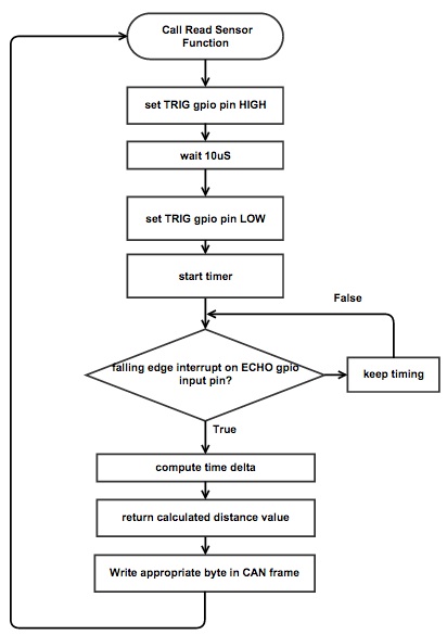

ADC based read:

CAN Frame write:

Motor Controller Team Software Design
The Motor module only has one running task. That is to listen to two CAN messages from the Master module (0x100 and 0x124). During each heartbeat (0x100), Motor will send back an acknowledgement CAN message (0x200) and send the current forward speed value and neutral steer value with a CAN message (0x221) for the I/O module. When Motor receives (0x124) from Master, it will unpack that CAN message and execute the given movement command, which can be seen in the table below.

Motor Movement Commands
| Master CAN Payload Value | Movement Command |
|---|---|
| 0 | No command |
| 1 | Slow forward |
| 2 | Fast forward |
| 3 | Slow reverse |
| 4 | Fast reverse |
| 5 | Slow right forward |
| 6 | Slow left forward |
| 7 | Slow right reverse |
| 8 | Slow left reverse |
| 9 | Stop |
I/O Team Software Design
The I/O Software is based off of two tasks: The Event Handler Task and the RX Task.
Event Handler Task (High Priority):
This Task receives any immediate messages sent from the uLCD, processes the message, and sends the message to the CAN BUS.
This task enables the system to: Turn On/Off the Vehicle and Change Vehicle Modes.
RX Task (Low Priority):
This task receives all messages from the CAN BUS, and outputs message data onto the uLCD
High Level IO Software Logic

Event Handler Task Logic

RX Task Logic

Communication Bridge + Android Software Design
Prior to initializing tasks. a Bluetooth connection check function is called. This function blocks the system from initializing tasks until a successful Bluetooth connection is established. This check function watches the UART2 channel (where the Bluetooth module is connected) and checks for a specific string before it allows the tasks to be initialized. The string is sent from the Android device once it successfully initiates a data connection with the SJOne board.
The communication bridge software design is comprised of two tasks: terminal task and an RX/TX task.
After this is checked, the terminal task and RX/TX tasks are initialized.
High-Level Bridge Software Logic

Terminal Task (High Priority)

RX/TX Task (Medium Priority)

Android Application
An Android application was created that would send messages to a selected paired device. This application would first display a list of paired devices and prompt the user to select a paired device to connect to:

After successfully connecting, the application shows a Google Map on the left side and various buttons on the right side. There is always a floating pin in the center of the map. Upon setting a waypoint, the a pin is dropped at the specified location. Waypoints are cleared when turning the vehicle off.

The functionality of the buttons is as follows:
Vehicle Off: Sends the message "bluecmd 056" over Bluetooth.
GPS Mode: Sends the message "bluecmd 051" over Bluetooth.
Vehicle On: Sends the message "bluecmd 057" over Bluetooth.
Set Waypoint: Sends the message "bluenav [latitude], [longitude]" over Bluetooth.
Start Driving: Sends the message "bluecmd 055" over Bluetooth.
These messages are received by the XBee Bluetooth module and parsed by the terminal task. The terminal task then sends the corresponding CAN messages.
Geographical Controller Team Software Design
The following diagram shows the software design we followed for the duration of this project.

All the tasks involved are initialized inside the board_init.cpp file underneath the FullInit() function. All this function does is add tasks to the scheduler in the program as shown in the following figure.

GPS_L_Task: Uses the GPS API developed by one of our members to compute GPS location, heading, and time data as well as modify the relative can_msg_t types simultaneously.
HeadingTask: Uses Heading API developed by one of our members to retrieve information from the compass device regarding magnetometer and accelerometer readings. It also takes in data regarding the destination coordinates and computes bearing.
CanRx_task: Watches for any incoming messages meant for the GPS controller (filters by message ID). It also has this super-cool feature where it makes an LED on the host micro-controller blink when there is an incoming message. Function is called makeBlinkyLightGoWhenRx().
CanTx_task: Transmits the can_msg_t types at the rate of the specified enum parameter.
Master Controller Team Software Design
The master controller has a single receive task that fans out the messages into individual "modules". The modules then either store the data from the incoming messages into the module's variables, or call the vehicle logic API functions to alter the state of the vehicle.

Each module includes a queue that stores messages until the module has the opportunity to process it. The module code then processes the received message, which can include updating the module's variables. Module variables include data such as the current GPS location. All modules are friends of the vehicle logic class, so the vehicle logic can access these variables to get their data.

Software Interface
Sensor Controller Team Software Interface
 -can_comm.cpp Tasks that retrieve sensor values and send them to CAN bus.
 -main.cpp Calling all the tasks that are implemented in can_comm.cpp
Motor Controller Team Software Interface
The main function initializes the CAN bus and proceeds to call the only task called CAN_rx_tx.
 -CAN_rx_tx.hpp contains an object declaration for a task that receives and sends out CAN messages.
 -CAN_rx_tx.cpp contains instructions on what CAN message IDs to listen for and what to execute when
  those messages are received.
 -motor_typedef.h contains nomenclature for values used within the program.

I/O Team Software Interface


Communication Bridge + Android Software Interface


Geographical Controller Team Software Interface
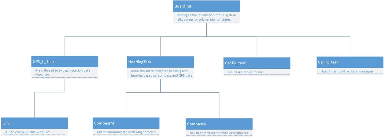

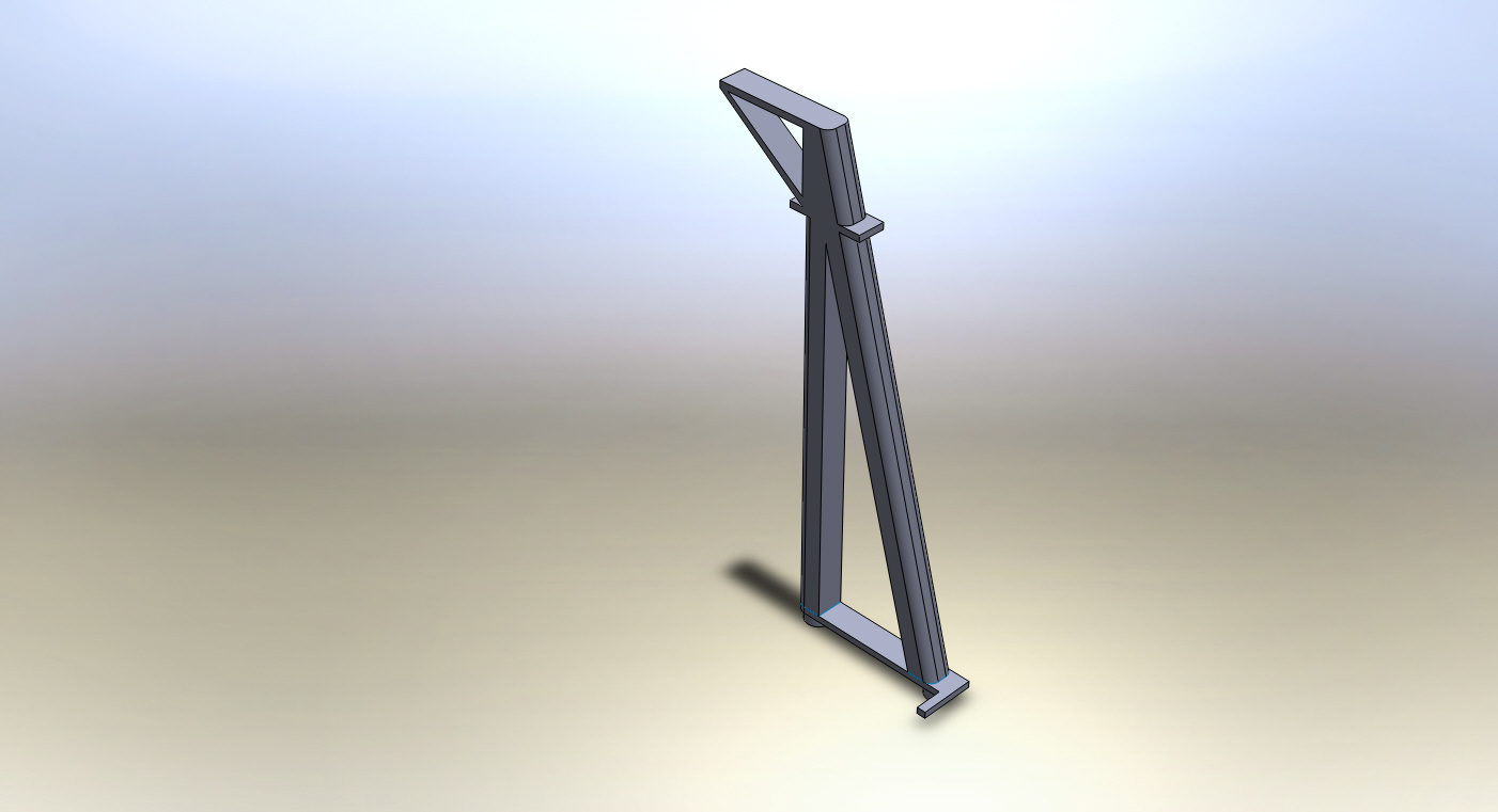
Master Controller Team Software Interface
The primarily interaction between software level and hardware level was done over the CAN interface.
CAN Communication Table
Master CAN Communication Table
| TX Message ID | TX Message Transmit Rate | TX Message Description | RX Response Message ID | RX Listening Module |
|---|---|---|---|---|
| 0x100 | 1hz Periodic | Request Heartbeat (Module state and Timestamp) | 0x200, 0x300, 0x400, 0x500, 0x600 (Respectively) | Motor, Sensor, Geo, Bridge, IO (Respectively) |
| 0x101 | 1hz Periodic | Send Vehicle State | N/A | Motor, Sensor, Geo, Bridge, IO |
| 0x124 | Spontaneous | Set Torque and Steering | N/A | Motor |
| 0x140 | Spontaneous | Send Destination GPS | N/A | Geo |
| 0x14A | Spontaneous | Request Calibrate Compass | N/A | Geo |
| 0x14B | Spontaneous | Request Compass Heading | N/A | Geo |
| 0x14C | Spontaneous | Request Current GPS | N/A | Geo |
| 0x14D | Spontaneous | Request Current Time | N/A | Geo |
Motor CAN Communication Table
| TX Message ID | TX Message Transmit Rate | TX Message Description | RX Response Message ID | RX Listening Module |
|---|---|---|---|---|
| 0x221 | 1z Periodic | Transmits forward speed and neutral steer values. | N/A | I/O |
Sensor CAN Communication Table
| TX Message ID | TX Message Transmit Rate | TX Message Description | RX Response Message ID | RX Listening Module |
|---|---|---|---|---|
| 0x330 | 10hz Periodic | Transmit all sensor's distances | N/A | Master, IO |
Geo CAN Communication Table
| TX Message ID | TX Message Transmit Rate | TX Message Description | RX Response Message ID | RX Listening Module |
|---|---|---|---|---|
| 0x441 | 10hz Periodic | Transmit Current GPS Coordinates | N/A | Master, IO |
| 0x445 | 10hz Periodic | Transmit Current Heading and Bearing | N/A | Master, IO |
| 0x449 | 10hz Periodic | Transmit Current GPS Heading | N/A | Master, IO |
| 0x465 | Spontaneous | Signal User that Calibration is complete | N/A | I/O |
Bridge CAN Communication Table
| TX Message ID | TX Message Transmit Rate | TX Message Description | RX Response Message ID | RX Listening Module |
|---|---|---|---|---|
| 0x050 | Spontaneous | Request Drive Mode change to Free Drive | N/A | Master |
| 0x051 | Spontaneous | Request Drive Mode change to GPS Drive | N/A | Master |
| 0x052 | Spontaneous | Request Drive Mode change to Indoor Drive | N/A | Master |
| 0x053 | Spontaneous | Transmit Destination GPS Coordinates | N/A | Master |
| 0x055 | Spontaneous | Request Vehicle Start Driving Command | N/A | Master |
| 0x056 | Spontaneous | Request Vehicle Turn Off | N/A | Master |
| 0x057 | Spontaneous | Request Vehicle Turn On | N/A | Master |
| 0x058 | Spontaneous | Send Free Drive Turn Left | N/A | Master |
| 0x059 | Spontaneous | Send Free Drive Straight | N/A | Master |
| 0x05A | Spontaneous | Send Free Drive Turn Right | N/A | Master |
| 0x05B | Spontaneous | Send Free Drive Stop | N/A | Master |
| 0x05C | Spontaneous | Send Free Drive Reverse Left | N/A | Master |
| 0x05D | Spontaneous | Send Free Drive Reverse Straight | N/A | Master |
| 0x05E | Spontaneous | Send Free Drive Reverse Right | N/A | Master |
IO CAN Communication Table
| TX Message ID | TX Message Transmit Rate | TX Message Description | RX Response Message ID | RX Listening Module |
|---|---|---|---|---|
| 0x060 | Spontaneous | Request Drive Mode change to Free Drive | N/A | Master |
| 0x061 | Spontaneous | Request Drive Mode change to GPS Drive | N/A | Master |
| 0x062 | Spontaneous | Request Drive Mode change to Indoor Drive | N/A | Master |
| 0x063 | Spontaneous | Request Vehicle Turn On | N/A | Master |
| 0x064 | Spontaneous | Request Vehicle Turn Off | N/A | Master |
| 0x065 | Spontaneous | Transmit Destination GPS Coordinates | N/A | Master |
| 0x066 | Spontaneous | Request Vehicle Start Driving Command | N/A | Master |
| 0x067 | Spontaneous | Start Geo Calibration | N/A | Geo |
Testing
Sensor Controller Testing
Sensor Controller Testing #1
1. For individual sensors: Set a obstacle(36" x 48" poster board) in front of a sensor and sensor team verifies the sensor values with a ruler. Repeat this process with different distances (20cm, 40cm,and 60cm).
2. Detect any outlier: Set a obstacle and allow sensor to detect for period of time and sensor team verifies values within the period. If there were outliers, sensor team would verify the wiring or write a filtering algorithm.
3. Integrated test: After all sensors are tested individually, sensor team tested collaboratively with master. Sensor team would sent CAN message (5 sensor values) to master team and check if master team can perform certain operations according to different sensor values.
Motor Controller Testing
Motor Controller Testing #1
Testing for the motor was done using a digital oscilloscope to probe for PWM signals. Through the usage of Preet's PWM API, various values were tested to find the range of usable values in order to attain a PWM signal width of 1ms to 2ms. It was found that using a PWM frequency of 100hz, a range between 10 and 20 were representative of a PWM duty cycle of 0% to 100%. 0%~49% equated to a left steer or a reverse throttle, while 51%~100% equated to a right steer or forward throttle. To get neutral steer or zero throttle, a 50% duty cycle was used.
However, a lot of trial and error testing were done to find suitable speeds and steering ratios. This had to be done manually by testing value ranges and physically running the car to hand pick PWM values that allowed the car to move in a slow, but steady pace.
I/O Testing
I/O Testing #1: uLCD UART Communication
Testing the following uLCD API calls:
-Write String - Able to write a simple "Hello World" onto the uLCD
-Write int to String - Able to write an integer variable onto the uLCD
-Write float to String - Able to write a float variable onto the uLCD
-uLCD TX events
I/O Testing #2: CAN COMMUNICATION
-CAN RX - Tested if all CAN messages on the BUS are being received on time
-CAN TX - Tested if all CAN messages being sent on time BUS on time
I/O Testing #3: Data Processing
-Event Handler Task - Tested if all uLCD operations are being handled and sent to the CAN Bus
-RX Task - Tested if all messages are received, processed, and displayed onto the uLCD
Communication Bridge + Android Testing
Communication Bridge + Android Testing #1: Terminal Commands
Two new terminal commands were added to the existing terminal task: bluenav (for sending coordinates over CAN) and bluecmd (for sending other messages over CAN). In order to test the functionality of these commands, a logging function was built into each new function. Various commands were sent to the terminal, the log file was subsequently viewed, and it was confirmed that these two terminal tasks parsed the inputs properly and would send the expected messages.
Communication Bridge + Android Testing #2: Android Bluetooth messages
The Android application's message sending functionality was tested. First, the Android device was paired with a laptop. After successful pairing, a serial terminal was opened between the laptop and Android device via Bluetooth. Buttons were pressed on the Android application, and it was confirmed that the expected messages were being sent from the Android application over Bluetooth, as they could be read in the serial terminal on the laptop.
Communication Bridge + Android Testing #3: Full System
After confirming operation of the Android application and the new terminal commands, the full system was tested. The bridge board was connected to the master board, and the Android device was paired with the SJOne board. Buttons were pressed on the Android application, and proper operation was confirmed in two ways: looking at the serial output of the master board and viewing sent GPS coordinates on the LCD screen. All messages were sent as expected.
Geographical Controller Testing
Geographical Controller Testing - Overall System
There are two devices interfaced with the Geographical Controller, the GPS and compass. The GPS is responsible for retrieving the coordinates of the device's location and the compass is responsible for producing magnetometer and accelerometer data. Therefore there are three things that must be tested: GPS, magnetometer, and accelerometer data. There are simple test cases that could be made to verify that the values produced by these modules are correct. Take the GPS module for example, by comparing the latitude and longitude from the module to the true values of its location (from Google maps), one can verify the functionality of the device.
Geographical Controller Testing - GPS
Testing the GPS module is straightforward. To verify that we can retain the values of the module's current location, we continuously physically changed locations and compared them to the values given by Google Maps. The printf() function was extensively used throughout the duration of this test to see what the module was producing so it could be compared with the true values provided by Google.
Geographical Controller Testing - Compass
We needed the compass for two things: accelerometer and magnetometer readings. The first thing to test is the accuracy of these values. Following a similar test case for the GPS module, we tested (and calibrated when necessary) the values for the accelerometer and magnetometer. Using printf statements, we observed the values returned by the module. This is where we first noticed that the accelerometer values were erratic at times and could not produce reliable results. Furthermore, this is also how we discovered that the magnetometer did not produce negative values when it should have been. Rather, it produced the negative value with 2^16 added to it. Knowing this, we were able to implement a correction algorithm. Once those values were verified, the algorithm to calculate heading was developed and tested.
Master Controller
Master Controller Testing
We tested master controller by working directly with each individual module team. We would test communication over CAN with each module then test functionality with each module. We tested master controller by doing integration test with sub module teams into the overall vehicle.
Technical Challenges
Sensor Controller Team Issues
ISSUE #1 Unreliable sensor values
PROBLEM: Fluctuating sensor values
RESOLUTION: Implement a sensor filtering function that discard the values that are considered as outliers. 5 sensor values were taken and average to get the final sensor value. This way makes the values more stable. We also compare the current sensor value and the previous sensor value and see if the difference is within tolerance, if it's not, the current value will be discarded and replace by the previous value.
FUTURE RECOMMENDATIONS: Read the data sheet carefully and test the sensor thoroughly before pass sensor values to the next team.
ISSUE #2 Bad hardware connections
PROBLEM:Bad hardware connections: A lot of time were wasted in software debugging, which the issue was in hardware.
RESOLUTION: Solder all sensor pin connections.
FUTURE RECOMMENDATIONS: Before any software debugging, the hardware connections must be the first area to check because it is the easiest and fastest.
Motor Controller Team Issues
Motor Controller Issue #1
PROBLEM: Going reverse during forward movement.
RESOLUTION: It was found out that a neutral-reverse-neutral-reverse signal had to be sent out with small amounts of vTaskDelay in order to do a reverse
FUTURE RECOMMENDATIONS: Find out how ESC unit controls reverse commands (no datasheets available).
Motor Controller Issue #2
PROBLEM: Braking during movement.
RESOLUTION: Go into neutral throttle and move wheels in the opposite direction of movement for a small amount of time.
FUTURE RECOMMENDATIONS: Try to learn how the ESC does a real brake, which should lock up the motor, thus preventing movement.
Motor Controller Issue #3
PROBLEM: How to vary speeds when going up a slope.
RESOLUTION: Use a speed sensor/wheel encoder to speed up car. (not able to implement)
FUTURE RECOMMENDATIONS: Prioritize mounting a hall sensor with magnetic strips as soon as motor module is able to control car movement.
I/O Team Issues
I/O Team Issue #1
PROBLEM:
Architecture which used a mutex to share UART lines between tasks was causing the button on the LCD display to not be very reliable.
RESOLUTION:
Instead of using a mutex, different priorities were used instead. The higher priority task will have complete control over the UART until it is done, however the higher priority task will only be active when there are user interactions with the LCD display.
FUTURE RECOMMENDATIONS:
Architectural design should be considered and planned out fully before coding.
I/O Team Issue #2
PROBLEM:
More performance enhancements needed to boost refresh rate for the LCD display. The display shows many different information (sensor values, motor information, etc.).
RESOLUTION:
Based on which form is activated on the screen (Sensor Form, Motor Form, etc.), the software would discard and not process information for other forms that do not need to be updated currently (with exception for Bridge).
FUTURE RECOMMENDATIONS:
Find areas for optimizations to better improve performance. If analyzed closer, there could be other areas which could improve performance, but the screen seemed sufficiently responsive now.
Communication Bridge + Android Team Issues
Communication Bridge + Android Issue #1
PROBLEM: The purchased XBee Bluetooth module failed to connect to any devices.
RESOLUTION: It was noted that the LEDs on the XBee Bluetooth module did not turn on, and it was assumed that the device was faulty. A second XBee Bluetooth module was purchased, and this module operated properly using the same code.
FUTURE RECOMMENDATIONS: Buy at least two Bluetooth modules in the event that one is faulty.
Communication Bridge + Android Issue #2
PROBLEM:When testing to see if the terminal task received the expected messages, the values would not print to the terminal.
RESOLUTION: It was assumed that the terminal task was operating properly and receiving commands from Bluetooth but printing the information back over UART. The terminal command code was rewritten to log information received instead of printing it. It was confirmed that messages were being received and parsed properly by the terminal task.
FUTURE RECOMMENDATIONS: Make extensive use of the built in logging function.
Communication Bridge + Android Issue #3
PROBLEM: After the implementation of the UART2 terminal interface, any use of UART2 through other tasks caused the terminal to act as if it received a command multiple times. This would cause the Bluetooth module to act erratically and stall.
RESOLUTION: Removed UART2 from all FreeRTOS tasks other than the terminal task. Created a Bluetooth initialization routine in the main function that would wait for a proper Bluetooth connection before starting the terminal task.
FUTURE RECOMMENDATIONS: Implement a watchdog function that will reboot the board upon termination of Bluetooth connections.
Geographical Controller Issues
Geographical Controller Issue #1
PROBLEM: Received jumbled sentences from GPS module.
RESOLUTION: Removed all delay_ms() calls and adjusted setRunDuration() until sentences were received without any corruption.
FUTURE RECOMMENDATIONS: Start with the most basic interface possible and make adjustments to any functions that cause delays. After that, more functionality can be added with confidence. Note that when involving tasks, the run duration may need to be adjusted as modules are added within the same task (for example, adding compass to the GPS task caused issues for the GPS).
Geographical Controller Issue #2
PROBLEM: Values from the accelerometer were not stable.
RESOLUTION: Implemented functions to calibrate. Upon boot, offsets are calculated by polling and averaging the values of x,y, and z at standstill and subtracting all those values from 0 (because 0 is the supposed values for x,y, and z during standstill). Whenever the accelerometer task grabs the values from the registers in the gps module, it will add the value of the corresponding offset, producing calibrated values.
FUTURE RECOMMENDATIONS: Create code to calibrate all modules to make sure the data produced are the same data that you're looking for before piecing the components together.
Master Controller Team Issues
Master Controller Issue #1
BACKGROUND Each of our sensors were supposed to transmit a value between 0 and 255 in centimeters. All sensor values are updated over CAN at a 10hz periodic rate.
PROBLEM: The consistency of a sensor value would fluctuate dramatically and never stay consistent with a tolerance of 5cm.
RESOLUTION: Ask the sensor team to filter their data.
FUTURE RECOMMENDATIONS: Assure the data being sent by sensors is filtered. If the issue cannot be resolved, work together with the Sensor Team to debug and solve the issue.
Master Controller Issue #2
BACKGROUND The heading being sent by Geo over CAN should be at a 10hz periodic rate.
PROBLEM: The consistency of a heading value would fluctuate dramatically and never stay consistent with a tolerance of 5 degrees.
RESOLUTION: Ask geo team to calibrate their heading data/ refactor calibration code.
FUTURE RECOMMENDATIONS: Assure that the heading data being sent by the Geo team is calibrated. If the issue cannot be resolved, work together with the Geo Team to debug and solve the issue.
Master Controller Issue #3
BACKGROUND Valid GPS latitude and longitude information transmitted over CAN should be at a 10hz periodic rate.
PROBLEM: The consistency of the gps latitude and longitude value wouldn't update at a 10hz periodic rate
RESOLUTION: Ask geo team to fix freeRTOS priority and timing issues with updating GPS latitude and longitude.
FUTURE RECOMMENDATIONS: Assure that the GPS latitude and longitude priority and timing issues are fixed. If the issue cannot be resolved, work together with the Geo Team to debug and solve the issue.
Master Controller Issue #4
BACKGROUND The vehicle would compare current GPS location to destination GPS location to determine if the vehicle should stop
PROBLEM: The algorithm to compare current GPS latitude and longitude to destination GPS latitude and longitude was comparing current latitude minus destination longitude. Because of this, the GPS comparison would be remotely close.
RESOLUTION: Fix current latitude to compare with destination latitude and current longitude with destination longitude.
FUTURE RECOMMENDATIONS: When debugging, review the overall algorithms to assure the design is valid.
Conclusion
Overall, the team can conclude this project to be a success. Advice to future students taking this class is to establish clear goals for each individual team member. For each subteam, tailor each team member's goal to their strengths to create an overall effective subteam. Even though the weather, GIT, hardware, and FreeRTOS may have been common obstacles everyone faced, the team was able to successfully create a self driving GPS RC car via 6 subsystems using CAN communication. The team learned other important skills as well, including: team dynamics, hardware interference, various protocols, algorithms, and team workflow. These skills that were gained through this project can be scaled into other projects within the field.
Project Video
Project Source Code
References
Acknowledgement
Any acknowledgement that you may wish to provide can be included here.
References Used
List any references used in project.