Difference between revisions of "F13: LED Display"
Proj user7 (talk | contribs) (→Parts List & Cost) |
Proj user7 (talk | contribs) (→Team Members & Responsibilities) |
||
| Line 25: | Line 25: | ||
*Project Management | *Project Management | ||
*Hardware Design and Build | *Hardware Design and Build | ||
| + | *Parts Procurement | ||
*Software Design | *Software Design | ||
*Test | *Test | ||
Revision as of 16:27, 23 November 2013
Contents
Grading Criteria
- How well is Software & Hardware Design described?
- How well can this report be used to reproduce this project?
- Code Quality
- Overall Report Quality:
- Software Block Diagrams
- Hardware Block Diagrams
- Schematic Quality
- Quality of technical challenges and solutions adopted.
Project Title
A Moderately Fancy LED Display
Abstract
This project will control several strings of household LED lights (i.e. Christmas lights) via a microcontroller. The LED display will be synced to a song playback.
Objectives & Introduction
This project will need to be able to control several relays with the microcontroller. The development board's GPIO header pins (P2.0 - P2.7) will be used to bias the gate of a FET, which will in turn drive the relay coil. The ADC will sync up the playback of the song to the LED display. The ADC will wait for the first beat of the song, and then begin the program. The LED timing and channel useage will be manually programmed to make a visually appealing show.
Team Members & Responsibilities
Mike Mellman
- Project Management
- Hardware Design and Build
- Parts Procurement
- Software Design
- Test
- Project Documentation
Schedule
| Task | Milestone? | Expected Duration | Actual Duration |
| Settle on project and approval by instructor | Y | 9/24 - 10/1 | 9/24 - 10/1 |
| Finalize channel count on dev and relay boards | 10/1 - 10/5 | 10/1 - 10/5 | |
| Identify vendors for parts | 10/1 - 10/5 | 10/1 - 10/5 | |
| Prepare proposal | 10/5 - 10/6 | 10/5 - 10/6 | |
| Final instructor approval | 10/8 | 10/8 | |
| Finalize circuit design | 10/8 - 10/15 | 10/8 - 10/12 | |
| Order online parts (long-lead from China) | Y | 10/8 - 10/15 | 10/12 |
| Buy parts from stores | Y | 10/8 - 10/15 | 10/12 - 11/16 |
| Pick song for display | 10/8-10/15 | 10/13 | |
| Work on code for timing LEDs | 10/15 - 11/22 | 10/15 - 11/22 | |
| Relay board in hand | 11/1 | 11/4 | |
| Build hardware setup | Y | 11/2 - 11/5 | 11/8 - 11/17 |
| Lecture on ADC | 11/5 | 11/5 | |
| Write code to sync LEDs to song playback | 11/6 - 11/9 | 11/9 - 11/16 | |
| Change LEDs to look good with song (for nice video) | 11/22 - 11/28 | 11/22 - 11/24 | |
| Complete report | Y | 11/28 - 12/3 | |
| Project presentation | Y | 12/3 | 12/3 |
Bill of Materials & Cost
| Ref Number | Part Number | Description | Vendor | Qty | Unit Cost | Total Cost |
| 1 | SJ One Board | SJSU development board, LPC1758 | SJSU Engineering | 1 | $75.00 | $75.00 |
| 2 | 20-018-902 | Solid state relay module, 5V, 8 channel | Sainsmart | 1 | $20.99 | $20.99 |
| 3 | 94781 | LED string, 60 count, multi-color, 110VAC | Holiday Time | 8 | $9.98 | $79.84 |
| 4 | 16082 | Extension cord, 8', indoor | Walmart | 8 | $6.37 | $50.96 |
| 5 | 8662K278 | Delrin sheet, black, 6x12x0.5" | McMaster-Carr | 1 | $28.19 | $28.19 |
| 6 | 91780A735 | Standoff, aluminum, 1/2" tall, 4-40 thread | McMaster-Carr | 12 | $0.27 | $3.24 |
| 7 | 91735A106 | Machine screw, 1/2", 4-40 thread, pan head | McMaster-Carr | 12 | $0.04 | $0.53 |
| 8 | 91771A110 | Machine screw, 1/2", 4-40 thread, flat head | McMaster-Carr | 12 | $0.05 | $0.55 |
| 9 | 7556K25 | Cable tie, 4 way | McMaster-Carr | 16 | $0.14 | $2.23 |
| 10 | ULA29V | 9V battery, alkaline | Radio Shack | 1 | $5.99 | $5.99 |
| 11 | 270-324 | 9V battery snap connector | Radio Shack | 1 | $2.99 | $2.99 |
| 12 | 270-1803 | Project enclosure, 5x2.5x2", ABS black | Radio Shack | 1 | $5.49 | $5.49 |
| 13 | LM317 | Voltage regulator | Fairchild | 2 | $0.56 | $1.12 |
| 14 | RN55D78R7FR36 | Resistor, 78.7ohm, 1%, 1/8W, axial lead | Vishay | 1 | $0.05 | $0.05 |
| 15 | RN55D1430RFR37 | Resistor, 143ohm, 1%, 1/8W, axial lead | Vishay | 1 | $0.05 | $0.05 |
| 16 | RN55D2370FR38 | Resistor, 237ohm, 1%, 1/8W, axial lead | Vishay | 2 | $0.05 | $0.10 |
| 17 | 50802-9001 | Square contact, for header post | Molex | 11 | $0.04 | $0.44 |
| 18 | 216-201 | Ferrule, 22AWG | Wago | 11 | $0.12 | $1.32 |
| 19 | 83006-009 | Hook up wire, 22AWG White, 5 feet | Belden | 1 | $2.50 | $2.50 |
| 20 | 83006-002 | Hook up wire, 22AWG Red, 2 feet | Belden | 1 | $1.00 | $1.00 |
| 21 | 83006-010 | Hook up wire, 22AWG Black, 2 feet | Belden | 1 | $1.00 | $1.00 |
| 22 | 8916-010 | Hook up wire, 14AWG Black, 10 feet | Belden | 1 | $5.00 | $5.00 |
| 23 | 320553 | Ring terminal, #4 stud size, 22-16AWG | TE Connectivity | 2 | $0.24 | $0.48 |
| Project Total | $289.07 |
Design & Implementation
The design section can go over your hardware and software design. Organize this section using sub-sections that go over your design and implementation.
Hardware Design
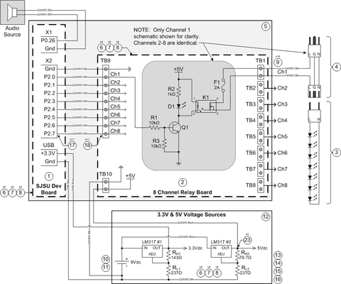
The system schematic is shown below in Figure 1 (with Bill of Material references).Each GPIO pin biases the gate of a transistor on the relay board. The voltage source on the relay board then has a conductive path to power the relay coil. The voltage sources use linear voltage regulators which control each output voltage. Each regulator's output voltage is set by the equation VOUT = VREF (1 + RL / RH).
For the LM317, VREF is a fixed voltage of 1.25Vdc, and RL is typically chosen to be 240Ω. The output voltage VOUT is fixed by the choice of RH.
Hardware Fabrication Steps
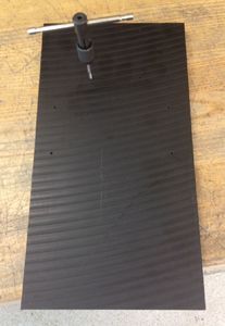
A piece of 1/2" Delrin sheet was obtained to hold the two boards and to give the AC wiring some strain relief. Holes for standoffs were drilled and tapped (see Figure 2).
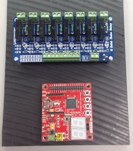
The boards were then mounted (see Figure 3) to the Delrin with Aluminum standoffs. The relay board was screwed down, since it would not need to be removed. The development board was held on with set screws for easy removal during the fabrication process.
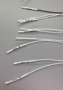
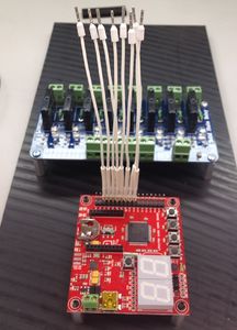
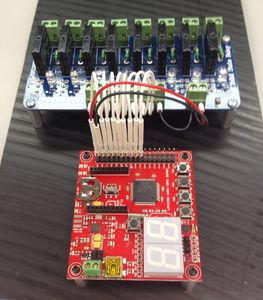
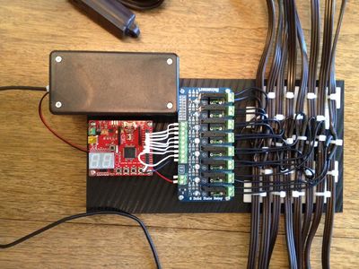
To attach the signal wires to the development board's header pins, a connector block was tried (to plug in all the signals at once). However, the correct contacts could not be obtained. Instead, each wire was terminated in a Molex-type contact that fit the header pins well. Each contact was then covered in white shrink tube to prevent shorting and to label each wire (see Figure 4). Each wire end that plugs into the relay board's screw terminal block was terminated in a Wago ferrule (see Figure 5). This wiring is shown in Figure 6. It should be noted that the 3.3V and ground wires were removed later due to higher voltage requirements.
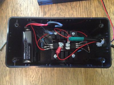
Per the vendor's datasheet, the Omron solid state relays require a control voltage of 4-6Vdc to switch. The use of the development board's 3.3Vdc bus voltage was unsuccessfully attempted in the chance that the relays might switch at a lower voltage than specified. If it had it worked, this would have eliminated the need for a second voltage source. As a result, a dual voltage source was designed and built. Using a 9V alkaline battery and two linear regulators, a 3.3Vdc and 5Vdc source was constructed (see Figure 7). The 5Vdc voltage source connected to the relay board with 2 wires. The 3.3Vdc source connected to the development board through a modified USB cable.
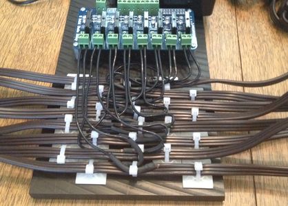
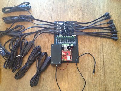
Extension cords were modified instead of the LED cords. This would allow the LEDs to be used in a more conventional fashion by the author's spouse upon the completion of this project. The AC line wire was carefully separated from the cord with an exacto blade and then cut. A piece of 14AWG wire was soldered to the exposed AC line wire to allow easier connection to the relay board's screw terminals. Each extension cord was mounted to the Delrin sheet using cable ties (see Figure 8). The voltage source box was attached to the Delrin sheet using velcro tape. The voltage wires were then hooked up to each board. The project hardware was complete, with the two boards powered by a battery only (see Figures 9 and 10). It should be noted that the 8 AC plugs are connected to 110Vac power by a power strip for convenience.
Hardware Interface
In this section, you can describe how your hardware communicates, such as which BUSes used. You can discuss your driver implementation here, such that the Software Design section is isolated to talk about high level workings rather than inner working of your project.
Software Design
Show your software design. For example, if you are designing an MP3 Player, show the tasks that you are using, and what they are doing at a high level. Do not show the details of the code. For example, do not show exact code, but you may show psuedocode and fragments of code. Keep in mind that you are showing DESIGN of your software, not the inner workings of it.
Implementation
This section includes implementation, but again, not the details, just the high level. For example, you can list the steps it takes to communicate over a sensor, or the steps needed to write a page of memory onto SPI Flash. You can include sub-sections for each of your component implementation.
Testing & Technical Challenges
Describe the challenges of your project. What advise would you give yourself or someone else if your project can be started from scratch again? Make a smooth transition to testing section and described what it took to test your project.
Include sub-sections that list out a problem and solution, such as:
Wifi Connection Issues
Many wifi connection issues were encountered. To solve this problem, a dedicated task was created to re-connect to wifi if the connection was ever lost.
Conclusion
Conclude your project here. You can recap your testing and problems. You should address the "so what" part here to indicate what you ultimately learnt from this project. How has this project increased your knowledge?
Project Video
Upload a video of your project and post the link here.
Project Source Code
Send me your zipped source code and I will upload this to SourceForge and link it for you.
References
Acknowledgement
Any acknowledgement that you may wish to provide can be included here.
References Used
List any references used in project.
Appendix
You can list the references you used.
