Difference between revisions of "F12: All Your Base are Belong to You"
(→Technical Challenges) |
(→Testing) |
||
| Line 186: | Line 186: | ||
==Testing and Technical Challenges== | ==Testing and Technical Challenges== | ||
===Testing=== | ===Testing=== | ||
| + | All the testing of the All Your Base are Belong to You Home automation and security system will be described in this section. | ||
| + | |||
| + | ====Testing Data of MLX90614 Thermal Sensor==== | ||
| + | First we must determine that we are gathering all 3 bytes gathered from the I2C read function, and ensure that it can be usable data for a security system. Then determine the distance of the Thermal sensor for the possible use as a motion sensor. | ||
| + | *The change in byte value by waving a hand over the sensor will confirm the functionality of the sensor | ||
| + | |||
| + | [[File:CmpE146_F12_AYB_MLX90614 Sensor Test.png|center|frame]] | ||
| + | <div style="text-align: center;">'''Figure 4:''' Command Parser Test </div> | ||
| + | |||
| + | ====Raspberry Pi Communication Test==== | ||
| + | For the Raspberry Pi, we will use a Linux OS and download a telnet software that is usable by the terminal program. | ||
| + | *First set up a Ad-hoc connection between the Raspberry Pi and the Motion Sensor Module | ||
| + | *Use telnet on a linux terminal to directly connect to the motion sensor module's IP and port for a direct communication | ||
| + | *Using hercules and the linux terminal, type in messages and hit enter on either hercules or the linux terminal to send a message | ||
| + | **Hercules should send a message to the Linux Terminal | ||
| + | **The Linux Terminal should send a message to the Hercules terminal | ||
[[File:CmpE146_F12_AYB_WiFlyTerminalUARTCom.PNG|center|frame]] | [[File:CmpE146_F12_AYB_WiFlyTerminalUARTCom.PNG|center|frame]] | ||
| Line 191: | Line 207: | ||
[[File:CmpE146_F12_AYB_RaspPiTerminal.png|center|frame]] | [[File:CmpE146_F12_AYB_RaspPiTerminal.png|center|frame]] | ||
| − | <div style="text-align: center;">'''Figure | + | <div style="text-align: center;">'''Figure 5:''' Wifly UART and Raspberry Pi Communication Test </div> |
| + | |||
| + | =====Testing the Slave Command Parser Function===== | ||
| + | The slave will be reading all data being transmitted from the website user interface. Once the data is received, the parser function will compare the hex and set global variables or send data depending on the command it has received. | ||
| + | |||
| + | [[File:CmpE146_F12_AYB_Parser Test.png|center|frame]] | ||
| + | <div style="text-align: center;">'''Figure 6:''' Command Parser Test </div> | ||
| + | |||
| + | ====User Interface Communication Test==== | ||
| + | With the use of a User interface to control the Motion Sensor, we will be using socket programming embedded in a website. The website will act as a user interface to enable to disable the device. | ||
| + | *Enable Button is pressed | ||
| + | **The sensor will be armed | ||
| + | ***When the sensor is armed, the sensor can go into an alarmed state if there is motion | ||
| + | |||
| + | *Disable Button is pressed | ||
| + | **The sensor will be disabled | ||
| + | ***Nothing will happen, even is there is motion | ||
| + | *Panic Button is pressed | ||
| + | **When the sensor is enabled, the sensor will be put into an alarm state and turn on an LED | ||
| + | **When the sensor is disabled, nothing will happen | ||
| + | [[File:CmpE146_F12_AYB_Website UI.png|center|frame]] | ||
| + | <div style="text-align: center;">'''Figure 7:''' Website User Interface </div> | ||
===Technical Challenges=== | ===Technical Challenges=== | ||
Revision as of 08:31, 10 December 2012
Contents
All Your Base are Belong to You
Abstract
The Automated Security system will monitor a home, and trip an if an intruder passes by the sensor by wirelessly sending a signal to the central unit. The system will incorporate several hardware devices, managed by a Web based GUI for easy activation and deactivation of both the alarm and the system
Objects & Introduction
This system will automate your security and home functions for a higher quality of life
Security Thermal Sensor
- Security Thermal Sensor will capture movement and heat from intruders
- Security Thermal Sensor will send an alarm signal to the server after the thermal value reaches a certain threshold
- Alarm Signal from the Security Thermal Sensor will be sent to the server through Wi-Fi communication
Raspberry Pi or Receiving Server (server)
- Server will receive data from the Security Thermal Sensor
- Server will receive alarm signal and be set to an alarm state until it is deactivated
Team Members & Responsibilities
- Christopher Cheng
- Wi-Fi Hardware and Software Design
- Tyler Gray
- Raspberry Pi (server) Research and Web UI
- Prateek Grover
- Thermal Motion Sensor Hardware and Software Design
Schedule
| Week Number | Scheduled Items | Actual |
|---|---|---|
| 1 |
|
|
| 2 |
|
|
| 3 |
|
|
| 4 |
|
|
| 5 |
|
|
| Week Number | Scheduled Items | Actual |
Parts List and Cost
| Item Number | Items | Cost |
|---|---|---|
| 1 |
Raspberry Pi |
$86.54 |
| 2 |
|
|
| 3 |
|
$19.95 |
| Item Number | Items | Cost |
Design and Implementation
Hardware Design
Hardware Implementation
Software Design
Software Implementation
Testing and Technical Challenges
Testing
All the testing of the All Your Base are Belong to You Home automation and security system will be described in this section.
Testing Data of MLX90614 Thermal Sensor
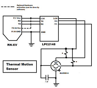
First we must determine that we are gathering all 3 bytes gathered from the I2C read function, and ensure that it can be usable data for a security system. Then determine the distance of the Thermal sensor for the possible use as a motion sensor.
- The change in byte value by waving a hand over the sensor will confirm the functionality of the sensor
Raspberry Pi Communication Test
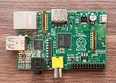
For the Raspberry Pi, we will use a Linux OS and download a telnet software that is usable by the terminal program.
- First set up a Ad-hoc connection between the Raspberry Pi and the Motion Sensor Module
- Use telnet on a linux terminal to directly connect to the motion sensor module's IP and port for a direct communication
- Using hercules and the linux terminal, type in messages and hit enter on either hercules or the linux terminal to send a message
- Hercules should send a message to the Linux Terminal
- The Linux Terminal should send a message to the Hercules terminal
Testing the Slave Command Parser Function
The slave will be reading all data being transmitted from the website user interface. Once the data is received, the parser function will compare the hex and set global variables or send data depending on the command it has received.
User Interface Communication Test
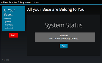
With the use of a User interface to control the Motion Sensor, we will be using socket programming embedded in a website. The website will act as a user interface to enable to disable the device.
- Enable Button is pressed
- The sensor will be armed
- When the sensor is armed, the sensor can go into an alarmed state if there is motion
- The sensor will be armed
- Disable Button is pressed
- The sensor will be disabled
- Nothing will happen, even is there is motion
- The sensor will be disabled
- Panic Button is pressed
- When the sensor is enabled, the sensor will be put into an alarm state and turn on an LED
- When the sensor is disabled, nothing will happen
Technical Challenges
Infrared Thermometer MLX90614
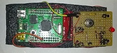
The sensor would not output data therefore the testing of the network connections between the motion sensor module and the raspberry pi could not be tested.
- Could not continue the utilization of the design and could not test and verify the usability of the MLX90614 Thermal Sensor as a motion sensor.
Determine the Problem
The wrong voltage was being passed into the MLX90614 was determined with the use of a multimeter.
- Requires around 3.3V but was getting voltage under 1V
- While minimum pressure was applied to the GND and V_out pins on the LPC2148 microcontroller, the correct voltage was being sent into the MLX90614.
- We have determined that the problem was with the LPC2148, the pins were not correctly soldered
Solving the Problem
Once we have determined the problem came from the LPC2148, we decided to re-solder a GND pin and a Voltage Out Pin to ensure that we can capture the full 3.3 Voltage going in and out of the MLX90614 system.


