F12: All Your Base are Belong to You
Contents
All Your Base are Belong to You
Abstract
The Automated Security system will monitor a home, and trip an if an intruder passes by the sensor by wirelessly sending a signal to the central unit. The system will incorporate several hardware devices, managed by a Web based GUI for easy activation and deactivation of both the alarm and the system
Objects & Introduction
This system will automate your security and home functions for a higher quality of life
Security Thermal Sensor
- Security Thermal Sensor will capture movement and heat from intruders
- Security Thermal Sensor will send an alarm signal to the server after the thermal value reaches a certain threshold
- Alarm Signal from the Security Thermal Sensor will be sent to the server through Wi-Fi communication
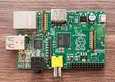
Raspberry Pi or Receiving Server (server)
- Server will receive data from the Security Thermal Sensor
- Server will receive alarm signal and be set to an alarm state until it is deactivated
Team Members & Responsibilities
- Christopher Cheng
- Wi-Fi Hardware and Software Design
- Tyler Gray
- Raspberry Pi (server) Research and Web UI
- Prateek Grover
- Thermal Motion Sensor Hardware and Software Design
Schedule
| Week Number | Scheduled Items | Actual |
|---|---|---|
| 1 |
|
|
| 2 |
|
|
| 3 |
|
|
| 4 |
|
|
| 5 |
|
|
| Week Number | Scheduled Items | Actual |
Parts List and Cost
| Item Number | Items | Cost |
|---|---|---|
| 1 |
|
$86.54 |
| 2 |
|
|
| 3 |
|
$19.95 |
| 4 |
|
$9.99 |
| 5 |
|
$60 |
| Item Number | Items | Cost |
Raspberry Pi
Setting up the Raspberry Pi
Setting Up the OS
- Download latest Raspbian Distribution and Win32DiskImager from RaspberryPi.org[1]
- Use the Disk Imager to create a bootable SD card of the Distribution[2]
Operating System
Once the OS has been installed onto an SD card with the use of the Disk Imager from a PC, the SD card can go straight into the Raspberry Pi. The first time the Raspberry Pi has been started, it must be plugged into a ethernet cord that has internet access in order to download any necessary files that has not been installed by the image file.
- Raspbian "Wheezy" from RaspberryPi.org
- Debian Linux variant
- Made Specifically for the Raspberry Pi
Wireless Connectivity
The Raspberry Pi does not have Wi-Fi Capabilities built in, so we used an Edimax EW 71UN nano adapter to give it that functionality. This adapter was chosen because it has the following qualities:
- IEEE 802.11 b/g/n capabilities
- nano adapter, so it won't stick out
- plug and play ability for Raspbian Wheezy Linux distribution
- cheap(cost $10 at time of purchase)
Configure Networking
In order for the Server to be able to connect with the sensor devices
- Created a shell script that runs on boot that will sets the ip and essid to an existing network
LAMP Server
- Linux, Apach, MySQL, PHP
- Makes Raspberry Pi a Web Server
- Hosts WebUI
Setting up the LAMP Server
With the Raspberry Pi OS set up, a few command line instructions were executed on the Pi to set it up as a Web Server. the following steps were taken from Penguin Tutor[3](an internet connection is necessary to install the LAMP elements):
- Update Repositories: sudo apt-get update
- Install Apache: sudo apt-get install apache2
- Install MySQL(needs password setup as part of the process): sudo apt-get install mysql-server
- Install PHP: sudo apt-get install php5
sudo apt-get install php5-mysql
WEB UI
- Gives user control over Security System
- Uses Twitter Bootstrap framework
- Allows User to Activate and Deactivate the Security System
- Uses Bootswatch to make it more visually appealing
SSH Tutorial
You can use an SSH from a PC to remotely access the Raspberry Pi to install packages, firmware upgrades, or applications.
- Open up the terminal on the Raspberry Pi
- Type in ifconfig
- Enter the ip address into the putty terminal then click on open
- The default login is: pi
- The default password is: raspberry
- Once logged in, use any Linux terminal command to remotely access the RPi
Design and Implementation
Hardware Design
Hardware Implementation
The hardware implementation for the project required the use of I2C bus for establishing communication between the temperature sensor and the micro controller. Along with that, wifly modules that would relay the information to the server were interfaced with the LPC board using Uart communication protocol.
Thermal Motion Sensor
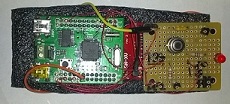
The sensor chosen to measure temperature readings was Melexis MLX90614 IR Temperature sensor[4]. This sensor required an input voltage of 3.3 V which is achieved by pulling the 3.3V output from the LPc2148 microcontrollers. In addition to that a decoupling capacitor with a value of 0.1 uF was interfaced between Vss and GND. Figure 1 shows the complete hardware circuit for the sensor.
I2C communication
The pins used for realizing this communication were Pin 0.2 for SCL and P 0.3 for SDA, which require a 4.7KOhm pull up resistor in order for the communication between SDA and SCL pins to function properly.
Wifly Interface
Wifly was interfaced over Uart line requiring two pins:Pin 0.8 TX for transmission and Pin 0.9 RX to receive data. A driver was Uart was already on hand(Uart 0) but it had to be modified to get Uart 1 since Uart 0 was already used by USB port.
Software Design
The Software Design consisted of:
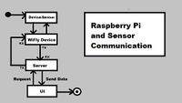
1. Raspberry Pi server generates requests using a WiFi microUSB adapter over the network.
2. The Web Server on the RPi will transmit the CMD Request to the Wi-Fly device with the corresponding IP Address.
3. Request is received by the LPC microprocessor which then controls sensor depending on the command received.
4. The GUI then stores the data given by sensor module.
Software Implementation
Security Trip Function
If the Sensor device is active, the security sensor will allow the data it receives from the MLX90614 Infrared Thermometer to activate the alarm.
Command Parsing
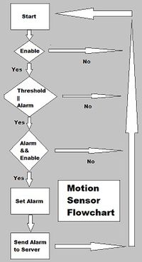
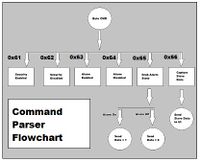
Upon receiving the request, the command parser decodes the incoming command which is received on the Uart RX line. The commands received manipulates security and alarm as shown in the figure below. Status of the system can send back to the server on the Uart TX line.
1. If the received byte is 0x61 or character "a", the system is armed and security is enabled.
2. If the received byte is 0x62 or character "b", the system is disarmed and security is disabled.
3. If the received byte is 0x63 or character "c", this means the sensor has crossed the threshold value and alarm gets enabled.
4. If the received byte is 0x64 or character "d", alarm gets disabled. It is used when the user wants to put the system out of alarm state.
5. Command "e" grabs the current alarm state status and send it to server: 1 for ON state , and 0 for OFF state.
6. Byte "f", send the current sensor value to the server.
CParse(Command, enable, alarm)
{
If (Command=0x61) // a
  Enable Security
Else If (Command=0x62) // b
  Clear Alarm bit
  Disable Alarm
  Disable Security
Else If (Command=0x63) // c
  Set Alarm bit
  Enable Alarm
Else If (Command=0x64) // d
  Clear Alarm bit
  Disable Alarm
Else if (Command=0x65)//e
  If Alarm is set
     Send 1
  Else
     Send 0
Else if (Command=0x66)//f
  data = I2cRead
  Send data to server

}
Testing and Technical Challenges
Testing
All the testing of the All Your Base are Belong to You Home automation and security system will be described in this section.
Testing Data of MLX90614 Thermal Sensor
First we must determine that we are gathering all 3 bytes gathered from the I2C read function, and ensure that it can be usable data for a security system. Then determine the distance of the Thermal sensor for the possible use as a motion sensor.
- The change in byte value by waving a hand over the sensor will confirm the functionality of the sensor
Raspberry Pi Communication Test
For the Raspberry Pi, we will use a Linux OS and download a telnet software that is usable by the terminal program.
- First set up a Ad-hoc connection between the Raspberry Pi and the Motion Sensor Module
- Use telnet on a linux terminal to directly connect to the motion sensor module's IP and port for a direct communication
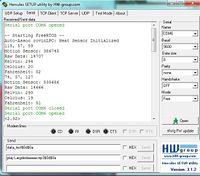
- Using hercules and the linux terminal, type in messages and hit enter on either hercules or the linux terminal to send a message
- Hercules should send a message to the Linux Terminal
- The Linux Terminal should send a message to the Hercules terminal
Testing the Slave Command Parser Function
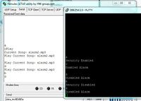
The slave will be reading all data being transmitted from the website user interface. Once the data is received, the parser function will compare the hex and set global variables or send data depending on the command it has received.
User Interface Communication Test
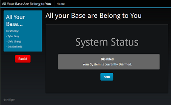
With the use of a User interface to control the Motion Sensor, we will be using socket programming embedded in a website. The website will act as a user interface to enable to disable the device.
- Enable Button is pressed
- The sensor will be armed
- When the sensor is armed, the sensor can go into an alarmed state if there is motion
- The sensor will be armed
- Disable Button is pressed
- The sensor will be disabled
- Nothing will happen, even is there is motion
- The sensor will be disabled
- Panic Button is pressed
- When the sensor is enabled, the sensor will be put into an alarm state and turn on an LED
- When the sensor is disabled, nothing will happen
Technical Challenges
In this section, we will describe all the technical challenges that we ran into while building and testing this project.
Infrared Thermometer MLX90614
The sensor would not output data therefore the testing of the network connections between the motion sensor module and the raspberry pi could not be tested.
- Could not continue the utilization of the design and could not test and verify the usability of the MLX90614 Thermal Sensor as a motion sensor.
Determine the Problem
The wrong voltage was being passed into the MLX90614 was determined with the use of a multimeter.
- Requires around 3.3V but was getting voltage under 1V
- While minimum pressure was applied to the GND and V_out pins on the LPC2148 microcontroller, the correct voltage was being sent into the MLX90614.
- We have determined that the problem was with the LPC2148, the pins were not correctly soldered
Solving the Problem
Once we have determined the problem came from the LPC2148, we decided to re-solder a GND pin and a Voltage Out Pin to ensure that we can capture the full 3.3 Voltage going in and out of the MLX90614 system.
UI Communication Problems
The Javascript functions we created that sent an AJAX request that would trigger communication to the sensor module caused all of the Javascript functions to fail.
Determine the Problem
There was a mismatch in variable names in the AJAX request, and the PHP request handler. This caused the request to be called, but not finish execution.
Solving the Problem
By commenting out pieces of the javascript functions, and the PHP handler, adding them little by little, we were able to debug and correct the problem.
Conclusion
After completing this project, we have learned about the various issues that can come up when completing a Wi-Fi Project. Things such as hardware failures, occurred with our sensor being faulty at first, as well as it's proclivity towards reading inconsistency over a long period of time. We also ran into software errors with our UI, most of which were fixed through rigorous debugging.
More importantly, we have learned how expansive the capabilities a micro controller has, with just a few added hardware and software components. Furthermore, we learned that there is a lot of information on a wide range of subjects related to embedded systems out on the internet, if you know the right google search terms.
Project Video
- Utilizes Raspberry Pi as Web Server
- Thermal Motion Trip Sensor
- Uses Laptop to access Web Server on RPi
[Thermal Motion Sensor + MP3 Alarm Demo]
- Uses WAMP localhost server on a laptop
- Thermal Motion Trip Sensor
- Mp3 Alarm Device
- Bump Speaker
[Thermal Motion Sensor + MP3 Alarm First Person View Demo]
- Uses WAMP localhost server on a laptop
- Thermal Motion Trip Sensor
- Mp3 Alarm Device
- Bump Speaker
Project Source Code
Project source code is available at SourceForge
- All code are zipped up in '.rar' files under the Files Tab
References
Acknowledgement
- Dr. Haluk Özemek
- Preet Kang
References Used
[1] http://www.raspberrypi.org/downloads
[2] http://www.softpedia.com/get/CD-DVD-Tools/Data-CD-DVD-Burning/Win32-Disk-Imager.shtml
[3] http://www.penguintutor.com/linux/raspberrypi-webserver
[4] http://www.melexis.com/Infrared-Thermometer-Sensors/Infrared-Thermometer-Sensors/MLX90614-615.aspx
Appendix
You can list the references you used.


