S22: Firebolt
Contents
FireBolt RC Car
Abstract
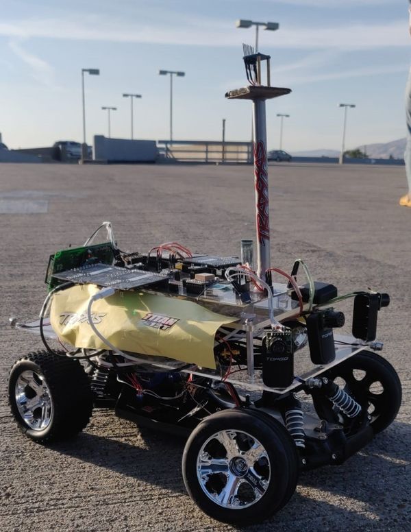
Firebolt is battery powered autonomous RC car. The car uses four microcontrollers for communication between the nodes- driver node, motor node, bridge & sensor node, and geological node over the CAN bus. It is interfaced to the mobile application which sends GPS coordinates for the destination location to the driver node and reaches the destination by avoiding any obstacles that comes in the path. For obstacle detection and avoidance it uses Ultrasonic Sensor and makes the decision of steering and maintaining speed after performing calculations based on the bridge and sensor node's data.
Objectives & Introduction
Objectives
The objective of this project is to get hands on experience of application of embedded systems in autonomous vehicles, have understanding of CAN bus communication, CAN database files, TDD and other related tools such as PCAN dongle and Busmaster.
Software side
- The car communicates with an Android application
- Receive coordinates from gps to drive itself to the destination while avoiding obstacles
- Display useful information on the LCD
- Take care of elevation and make correct speed decisions
- DBC file for all the nodes
Hardware side
- Design PCB for four controllers and other necessary components
- Choose good options for mounting the ultrasonic sensors on the car
- Make a good GUI Android application for interfacing with the microcontroller
Introduction
Four Nodes of the RC Car are:
- Driver Node
- GEO Node
- Sensors and Bridge Node
- Motor Node
- Mobile Application
Team Members & Responsibilities
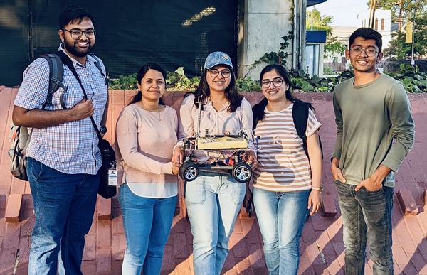
Priyanka Rai LinkedIn'
- Geo Controller
- GPS and Compass Interfacing
- Motor Controller
- Integration Testing
- Wiki Page Update
Ritu Patil LinkedIn'
- Motor Controller
- Integration Testing
- Wiki Page Update
Ritika Beniwal LinkedIn'
- Driver Node
- LCD interfacing
- Motor Controller
- Integration Testing
- Wiki Page Update
Utsav Savaliya LinkedIn'
- Sensor Controller
- Integration Testing
- Wiki Page Update
Dhanush Babu LinkedIn'
- Bluetooth module interfacing
- Motor Controller
- Android App
- Integration Testing
Schedule
| Week# | Start Date | Target Date | Task | Completion Date | Status |
|---|---|---|---|---|---|
| Week 1 |
|
|
|
|
|
| Week 2 |
|
|
|
|
|
| Week 3 |
|
|
|
|
|
| Week 4 |
|
|
|
|
|
| Week 5 |
|
|
|
|
|
| Week 6 |
|
|
|
|
|
| Week 7 |
|
|
|
|
|
| Week 8 |
|
|
|
|
|
| Week 9 |
|
|
|
|
|
| Week 10 |
|
|
|
|
|
| Week 11 |
|
|
|
|
|
| Week 12 |
|
|
|
|
|
Parts List & Cost
| Item# | Part Desciption | Vendor | Qty | Price($) |
|---|---|---|---|---|
| 1 | RC Car | Traxxas [1] | 1 | 280 |
| 2 | CAN Transceivers MCP2551-I/P | Comimark [2] | 5 | 8.99 |
| 3 | Ultrasonic Sensors | Max Botix[3] | 4 | 24.95 |
| 4 | GPS Breakout Board | Adafruit[4] | 1 | 29.95 |
| 5 | GPS Antenna | Adafruit[5] | 1 | 19.95 |
| 6 | RPSMA female to mhf4 | Superbat[6] | 1 | 7.99 |
| 7 | HC05 bluetooth RF Transceiver | HiLetgo[7] | 1 | 15.99 |
| 8 | Triple-axis Accelerometer | Adafruit[8] | 1 | 14.95 |
| 9 | Traxxas RPM Sensor | Traxxas[9] | 1 | 13.76 |
| 10 | Traxxas Battery and Charger | Traxxas[10] | 1 | 62.95 |
| 11 | Voltage Regulator | Valefod[11] | 6 | 10.99 |
| 12 | Headlights | Hobbypark[12] | 1 | 7.96 |
Printed Circuit Board
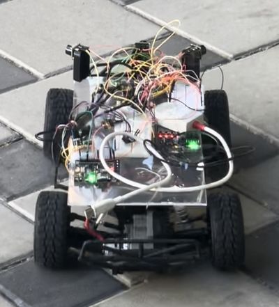
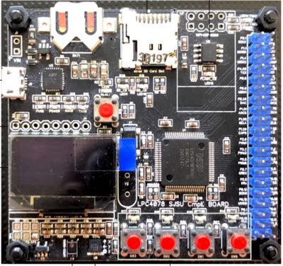
Initially we started our testing with mounting all our hardware on the breadboard (yes, it was messy and unstable!).
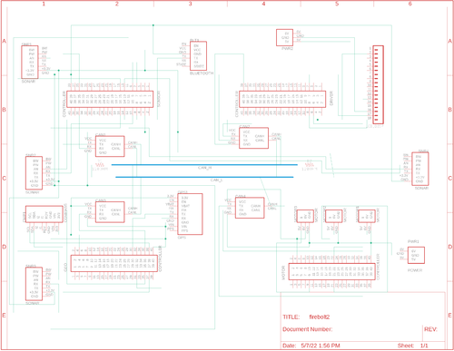
PCB Schematic
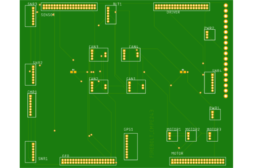
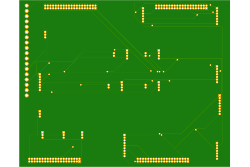
PCB Board
Challenges
- Since there are four controllers and a significant number of components (gps, sensors, can transceivers, volt regulator etc.) it was difficult for us to keep our hardware stable because every time we go for field testing some will get disconnected and we were kind of stuck up in the hardware setup.
- We decided to get the PCB printed but there were some issues and resolving them and getting a new PCB would take time.
Solution
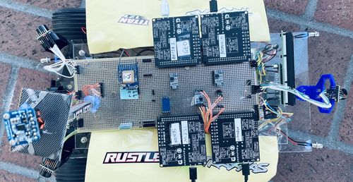
- Finally we decided to use the prototype board for mounting all the components and stabilizing our hardware.
CAN Communication
We used controller area network to communicate data between four nodes. All nodes are connected to each other through a physically conventional two wire bus CANH and CANL. The wires are a twisted pair with 120 Ω termination resistors at each end of the bus. 1s and 0s are transmitted as CAN High(0V difference) and Can Low(2v difference). A CAN frame has the following contents:
- Data Length Code (4bits)
- Remote Transmission Request.
- ID extend bit.
- Message ID (11 bit or 29 bit)
- Data bytes( depends on DLC)
- CRC
Arbitration: No two nodes will transmit at the same time because of arbitration. A lower Message-ID has a Higher priority on the CAN bus since 0 is the dominant bit.
Bit Stuffing: CAN bus stuffs extra bits when a long chain of multiple 1's or 0's occur to improve CAN integrity.
DBC File
The DBC file is a simple text file that consists of information for decoding raw CAN bus data to physical values or in human readable form.
| Sr. No | Message ID | Message function | Receivers |
|---|---|---|---|
| Driver command | |||
| 1 | 300 | Speed and steering direction for the motor | Motor |
| 2 | 100 | Driver Heartbeat | Motor, Sensor, Geo |
| Sensor And Bridge Controller | |||
| 3 | 200 | Sensor sonars from front, back, left ,right sensor | Driver |
| Motor Controller | |||
| 4 | 600 | motor speed, motor direction | Driver |
| Geo Controller | |||
| 8 | 400 | Bearing, Heading and Distance | Driver |
| Debug messages | |||
| 6 | 700 | Driver Debug | BRIDGE_SENSOR,MOTOR,GEO |
| 7 | 750 | Geo Debug | BRIDGE_SENSOR,MOTOR,GEO |
VERSION ""
NS_ :
    BA_
    BA_DEF_
    BA_DEF_DEF_
    BA_DEF_DEF_REL_
    BA_DEF_REL_
    BA_DEF_SGTYPE_
    BA_REL_
    BA_SGTYPE_
    BO_TX_BU_
    BU_BO_REL_
    BU_EV_REL_
    BU_SG_REL_
    CAT_
    CAT_DEF_
    CM_
    ENVVAR_DATA_
    EV_DATA_
    FILTER
    NS_DESC_
    SGTYPE_
    SGTYPE_VAL_
    SG_MUL_VAL_
    SIGTYPE_VALTYPE_
    SIG_GROUP_
    SIG_TYPE_REF_
    SIG_VALTYPE_
    VAL_
    VAL_TABLE_
BS_:

BU_: DRIVER MOTOR BRIDGE_SENSOR GEO DEBUG

BO_ 100 DRIVER_HEARTBEAT: 1 DRIVER
  SG_ DRIVER_HEARTBEAT_cmd : 0|8@1+ (1,0) [0|0] "" BRIDGE_SENSOR,MOTOR,GEO

BO_ 101 DRIVE_STATUS: 1 BRIDGE_SENSOR
  SG_ DRIVE_START_STOP : 0|8@1+ (1,0) [0|0] "" DRIVER

BO_ 200 SENSOR_SONARS: 5 BRIDGE_SENSOR
 SG_ SENSOR_SONARS_left : 0|10@1+ (1,0) [0|0] "cm" DRIVER
 SG_ SENSOR_SONARS_right : 10|10@1+ (1,0) [0|0] "cm" DRIVER
 SG_ SENSOR_SONARS_middle : 20|10@1+ (1,0) [0|0] "cm" DRIVER
 SG_ SENSOR_SONARS_rear : 30|10@1+ (1,0) [0|0] "cm" DRIVER

BO_ 250 DESTINATION_LOCATION: 8 BRIDGE_SENSOR
 SG_ DEST_LATITUDE : 0|28@1+ (0.000001,-90.000000) [-90|90] "degrees" GEO
 SG_ DEST_LONGITUDE : 28|28@1+ (0.000001,-180.000000) [-180|180] "degrees" GEO

BO_ 300 DRIVER_TO_MOTOR: 2 DRIVER
SG_ DRIVER_TO_MOTOR_speed : 0|8@1+ (0.1,-10) [-10|10] "kmph" MOTOR, BRIDGE_SENSOR
 SG_ DRIVER_TO_MOTOR_direction : 8|8@1+ (1,-45) [-45|45] "degrees" MOTOR, BRIDGE_SENSOR

BO_ 400 GEO_CONTROLLER_COMPASS: 8 GEO
  SG_ HEADING : 0|12@1+ (0.1,0) [0|359.9] "degrees" DRIVER, BRIDGE_SENSOR
  SG_ BEARING : 12|12@1+ (0.1,0) [0|359.9] "degrees" DRIVER,BRIDGE_SENSOR
  SG_ DISTANCE_TO_DESTINATION: 24|32@1+ (0.01,0) [0|359.9] "meters" DRIVER,BRIDGE_SENSOR

BO_ 600 MOTOR_SPEED: 2 MOTOR
SG_ MOTOR_SPEED_info : 0|8@1+ (0.1,-10) [-10|10] "kmph" DRIVER, BRIDGE_SENSOR


BO_ 700 DRIVER_DEBUG: 2 DEBUG
  SG_ car_driving_status: 0|8@1+ (1,0) [0|0] "" DEBUG
  SG_ car_steering_status: 8|8@1+ (1,0) [0|0] "" DEBUG

BO_ 750 GEO_CONTROLLER_DEBUG_MESG: 10 DEBUG
 SG_ CURR_LATITUDE : 0|28@1+ (0.000001,-90.000000) [-90|90] "degrees" DEBUG
 SG_ CURR_LONGITUDE : 28|28@1+ (0.000001,-180.000000) [-180|180] "degrees" DEBUG
 SG_ RAW_HEADING : 56|12@1+ (0.1,0) [0|359.9] "degrees" DEBUG

CM_ BU_ DRIVER "The driver controller driving the car";
CM_ BU_ MOTOR "The motor controller of the car";
CM_ BU_ SENSOR "The sensor controller of the car";
CM_ BO_ 100 "Sync message used to synchronize the controllers";
CM_ BU_ GEO "To provide raw GPS and compass heading";
CM_ SG_ 100 DRIVER_HEARTBEAT_cmd "Heartbeat command from the driver";

VAL_ 700 car_steering_status 2 "RIGHT" 1 "LEFT" 0 "STRAIGHT";
VAL_ 700 car_driving_status 2 "BACKWARD" 1 "FORWARD" 0 "STOPPED";
Sensor and Bluetooth ECU
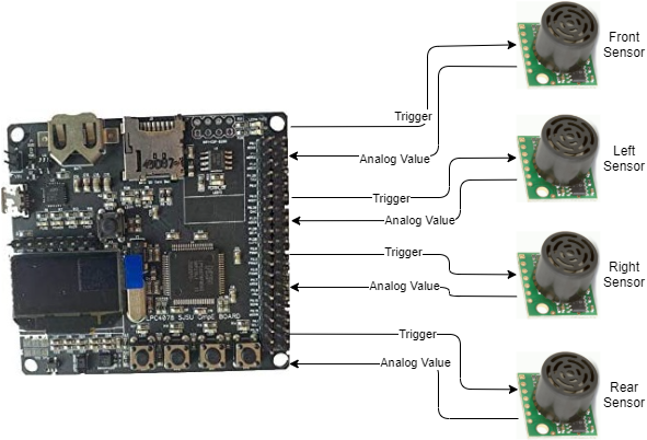
The obstacle detection sensors used here are Ultrasonic sensors. The HRLV-MaxSonar-EZ1 sensors from MaxBotix are used here. In these sensors there is membrane which needs to be triggered in order to generate and send ultrasonic objects every few seconds. When ultrasonic waves collide and come back and strikes with this membrane a pulse is generated which is used for sensing.
Software Design
The sensor node has to receive values from all the sensors and send the distance values on the CAN bus for the driver to run the obstacle avoidance logic.
1. Receive sensor values:
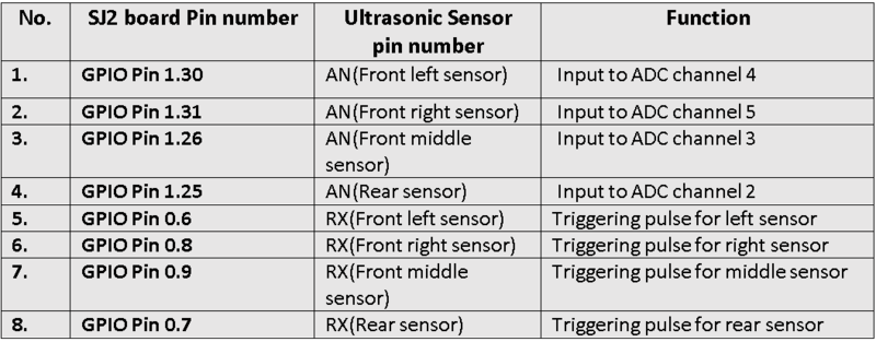
Four sensors are used here. Three in the front and one at the rear side. We need four ADC channels to address the receiving from all sensors. In order to use four pins on the SJ2 board we need to set the pins to analog mode. In the adc.h file and adc.c file there are only three channels initialized, so one needs to add ADC channel 3 in these files. On how to use these sensors, the datasheet of helped a lot. It addresses every aspect of how to use this particular sensor and the solution to most of the problem that can arise. All the sensor raw values are digitally converted in the range of 0 to 1024( 10 bit ADC). These value is in inches as mentioned in the datasheet. So, one needs to convert it into centimeter by applying some formula. The formula can be different based on the configuration used to setup the ADC channel even if same sensor is used.
Technical Challenges
The main challenge while using ultrasonic sensor with this particular project is of crosstalk. While detecting objects in the front all the front sensors waves are interfering with each other giving false values in the left or right sensor while the object is in the front only. The datasheet addresses this issues and what to do when multiple sensors are used in a system. It says that trigger each sensor are different time period in order to avoid crosstalk. So we triggered the front and rear at one particular time and left and right at one particular time. One sequence is triggered at psrticular 10Hz and other sequence is triggered at another 10Hz. There is a division of callbacks counts in 100Hz and a lock mechanism is used in order to used different 20Hz period out of 100Hz.
For frequency noise measurements like when the values suddenly change or vary between certain range sometimes, a filter is implemented. The most common filter for this type of use is median filter where a series of values are stored in a array and median is taken of all the values stored in that array.
Motor ECU
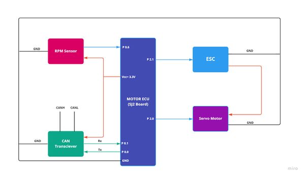
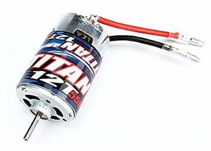
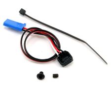
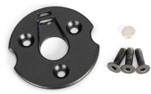
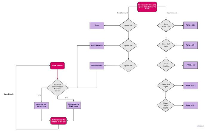
The Motor ECU acts as an encoder for the DC motor (used for propulsion) and Servo motor (used for turning the axle and changing direction of the car). The car is a two wheel drive with DC motor connected to the rear wheels and the servo motor is connected to the front wheels. The DC motor is controlled by Electronic Speed Control. The ECU supplies PWM signal to the ESC and the ESC powers the DC motor. The Servo motor is powered by the car battery as well and gets its PWM signal from the ECU. The RPM sensor sends its output to motor ECU by which the actual speed of the wheels is calculated.
Hardware Design
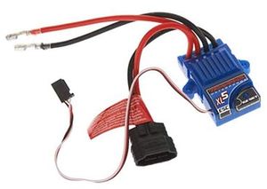
ESC & DC MotorThe DC motor is controlled by ESC using PWM signals provided by the motor controller for forward and reverse movements. We used the 9v NiMH battery to power up the ESC. The DC motor is powered by the ESC which has a dc-to-dc converter which converts 9v to 6v. The output from the ESC is used to power the Servo motor. ESC has an ease set button which is used for calibration and setting different modes for the car.
As we needed more than 50% speed for steep ramps, we used Sport mode. The frequency of the PWM signal fed to the servo motor is 100Hz. Based on the duty cycle set by the user, the car will go forward, reverse, or neutral. 10% - 20% duty cycle for reverse. 15% duty cycle for neutral. 15%-20% duty cycle for the forward motion.
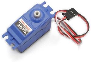
Servo MotorThe servo motor we used is Traxxas 2075 which was provided with the car and it is responsible for steering the car. It takes the 6V power directly from ESC. The servo motor is controlled directly from the SJ2 micro-controller board. The PWM signal fed to the servo motor is of frequency 100Hz. Based on the duty cycle of the signal sent to the servo, it rotates in the left / right direction. 10% - 20% duty cycle for left. 15% duty cycle for straight. 15%-20% duty cycle for right.
Software DesignThe motor node acts based on the speed and direction received over CAN bus from the Driver Node. The positive speed values are treated as forward motion and the negative speed values are considered to be the reverse motion of the RC car. The steering angles are divided into 5-degree segments and the motor node sends the pre-defined pwm duty cycle of the particular segment to the servo motor depending on the angle value received from the driver node.
Technical Challenges
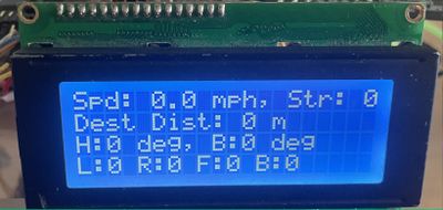
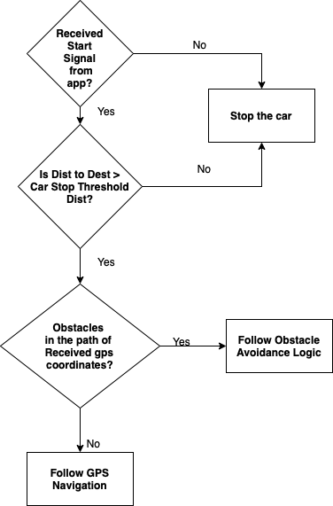
Geographical And Bridge ControllerHardware DesignSoftware DesignThe GEO controller consisted of 4 main parts which are: 1. GPS Module 2. Compass 3.Waypoints Algorithm 4. Geo Logic The Geo logic takes data from GPS module processes it to get current coordinates, takes data from compass for raw heading. After acquiring data from compass and GPS, it calculates heading , bearing and distance and sends it on CAN bus. 1. GPS Processing The GPS module uses UART1 to communicate with our SJ2 board. The API call for the GPS driver requires setting up the gps registers to only allow GPGGA data to improve processing. The main API function is called gps__run_once() which digests data from the physical GPS hardware. Inside gps__run_once(), we call two functions that help with parsing the gps coordinates. The first is taking using a line buffer for the UART characters that are digested during operation and checking if they are in fact a full GPGGA string. The second function parses those coordinates from the line buffer and converts them from GPGGA minutes data to polar coordinates. Once the function is called, global static variables located in geo_gps.c are used while a gps__get_coorindate() function is called whenever the API's data wants to be used outside of the gps.c file. In order to check if there is a gps fix, we created a function that checks if certain GPGGA bits are set or not. 2. Technical ChallengesDriver NodeDriver Node is the master controller. It receives input from sensor and bridge node, processes it to make right decision for controlling the speed and steering direction of the car and then commands the motor node to drive accordingly. This node is also interfaced to the LCD, which acts as dashboard of the car and displays information such as car speed and distance to destination on the screen. HardwareLCD is interfaced with the SJ2 board and it communicates over UART. P4.28 and P4.29 which is UART3 on board is used. Headlights and Tailights are also connected to the driver node using four GPIOs. Software Architecture Driver Logic
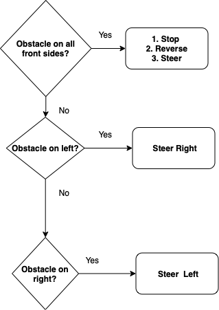
Obstacle Avoidance Logic
if (obstacle_on_all_front_sides()) {
          stop_the_car();
          reverse_car_and_steer();
        } else if (obstacle_on_left() && obstacle_in_right() && (!obstacle_on_front())) {
          drive_forward();
        } else if (obstacle_on_left() && (!obstacle_in_right())) {
          obstacle_on_right = false;
          get_steering_range(obstacle_on_right); // right steer
        } else if (obstacle_in_right() && (!obstacle_on_left())) {
          obstacle_on_right = true;
          get_steering_range(obstacle_on_right); // left steer
        } else if (obstacle_on_front() && (!obstacle_on_left() && !obstacle_in_right())) {
          stop_the_car();
          reverse_car_and_steer();
          obstacle_on_right =
              (internal_sensor_data.SENSOR_SONARS_right < internal_sensor_data.SENSOR_SONARS_left) ? true : false;
          get_steering_range(obstacle_on_right);

        } else if (obstacle_on_rear() && (!obstacle_on_all_front_sides())) {
          obstacle_on_right =
              (internal_sensor_data.SENSOR_SONARS_right < internal_sensor_data.SENSOR_SONARS_left) ? true : false;
          get_steering_range(obstacle_on_right);
          debug_values.car_driving_status = FORWARD;
          debug_values.car_steering_status = STRAIGHT;
        } else {
          stop_the_car();

          debug_values.car_driving_status = STOPPED;
          debug_values.car_steering_status = STRAIGHT;
        }
  if (obstactle_on_right == true) {
    //steer left
    motor_signal.DRIVER_TO_MOTOR_direction = (motor_signal.DRIVER_TO_MOTOR_direction <= 40)
                                                 ? motor_signal.DRIVER_TO_MOTOR_direction + offset_to_angle
                                                 : max_angle_threshold;
    motor_signal.DRIVER_TO_MOTOR_speed = slow_speed;
    update_lights(10, headlight_left);

  } else {
    //steer right
    motor_signal.DRIVER_TO_MOTOR_direction = (motor_signal.DRIVER_TO_MOTOR_direction >= -40)
                                                 ? motor_signal.DRIVER_TO_MOTOR_direction - offset_to_angle
                                                 : -max_angle_threshold;

    motor_signal.DRIVER_TO_MOTOR_speed = slow_speed;
    update_lights(10, headlight_right);
  }
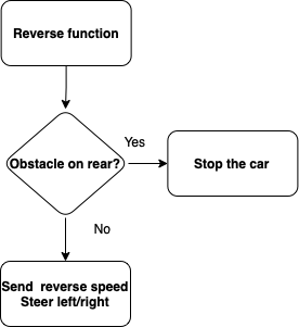
Reverse and Steer
  if (!obstacle_on_rear()) {
    motor_signal.DRIVER_TO_MOTOR_direction = 0;
    motor_signal.DRIVER_TO_MOTOR_speed = reverse_speed;
    update_lights(10, taillight_left);
    update_lights(10, taillight_right);
  } else {
    stop_the_car();
  }
Driver receives raw heading and bearing from the Geo node and in order to calculate the turning direction, it first computes the difference between heading and bearing. Then based on which quadrant the difference lies and where the destination lies, take navigation decisions to steer left, right or straight.
if (heading_difference >= 350 && heading_difference <= 10) {
    gps_navigation_direction = straight;
    heading_difference = fabs(heading_difference);

    debug_values.car_driving_status = FORWARD;
    debug_values.car_steering_status = STRAIGHT;
  } else if (heading_difference > 180) {
    gps_navigation_direction = left;
    heading_difference = 360 - heading_difference;

    debug_values.car_driving_status = FORWARD;
    debug_values.car_steering_status = LEFT;

  } else if (heading_difference < 0 && heading_difference > -180) {
    gps_navigation_direction = left;
    heading_difference = fabs(heading_difference);

    debug_values.car_driving_status = FORWARD;
    debug_values.car_steering_status = LEFT;
  }

  else if (heading_difference < -180) {
    gps_navigation_direction = right;
    heading_difference = fabs(heading_difference + 360);

    debug_values.car_driving_status = FORWARD;
    debug_values.car_steering_status = RIGHT;
  } else if (heading_difference > 0 && heading_difference <= 180) {
    gps_navigation_direction = right;

    debug_values.car_driving_status = FORWARD;
    debug_values.car_steering_status = RIGHT;
  }
Technical Challenges
Mobile ApplicationUser InterfaceSoftware DesignMaps ActivityBluetooth/WIFITechnical Challenges
ConclusionProject VideoProject Source CodeAdvise for Future Students
AcknowledgementReferenceshttp://socialledge.com/sjsu/index.php/Industrial_Application_using_CAN_Bus
|
