S22: Firebolt
Contents
FireBolt RC Car
Abstract
The Firebolt project is a path finding and obstacle avoiding RC car. The RC Car can interface with an Android application to get new coordinates to travel to, and will do so all while avoiding obstacles visible by ultrasonic sensors.
Objectives & Introduction
Objectives
- RC car can communicate with an Android application to:
- Receive new coordinates to travel to
- Send diagnostic information to the application
- Emergency stop and start driving
- RC car can travel to received coordinates in an efficient path while avoiding obstacles
- RC car can maintain speed when driving on sloped ground
- Design printed circuit board (PCB) to neatly connect all SJ2 boards
- Design and 3D print sensor mounts for the ultrasonic sensors
- Design a simple and intuitive user interface for the Android application
- Design a DBC file
Introduction
The Firebolt RC car uses 4 SJ2 boards as nodes on the CAN bus
- Driver and LCD
- GEO and path finding
- Sensors and bridge app
- Motor
Team Members & Responsibilities
- Geographical Controller
- Master Controller
- Android Application Developer
- Communication Bridge Controller
- Master Controller
- Sensors Controller
- Hardware Integration
- PCB Designing
Schedule
| Week# | Start Date | End Date | Task | Actual Completion | Status |
|---|---|---|---|---|---|
| 1
03/01 to 03/07 Start of Phase 1 |
|
|
|
|
|
| 2
03/08 to 03/14 |
|
|
|
|
|
| 3
03/15 to 03/21 |
|
|
|
|
|
| 4
03/22 to 03/28 |
|
|
|
|
|
| 5
03/29 to 04/04 End of Phase 1 |
|
|
|
|
|
| 6
04/05 to 04/11 Start of Phase 2 |
|
|
|
|
|
| 7
04/12 to 04/18 |
|
|
|
|
|
| 8
04/19 to 04/25 End of Phase 2 |
|
|
|
|
|
| 9
04/26 to 05/02 Start of Phase 3 |
|
|
|
|
|
| 10
05/03 to 05/09 |
|
|
|
|
|
| 11
05/10 to 05/16 End of Phase 3 |
|
|
|
|
|
Parts List & Cost
| Item# | Part Desciption | Vendor | Qty | Cost |
|---|---|---|---|---|
| 1 | RC Car | Traxxas [1] | 1 | $250.00 |
| 2 | CAN Transceivers MCP2551-I/P | Comimark [2] | 5 | $7.00 |
| 3 | Ultrasonic Sensors | Max Botix[3] | 5 | $150.00 |
| 4 | GPS and Antenna | Adafruit[4] | 1 | $60.00 |
| 5 | HC05 bluetooth RF Transreceiver | HiLetgo[5] | 1 | $12.59 |
| 6 | Triple-axis Accelerometer | Adafruit[6] | 1 | $21.40 |
| 7 | Traxxas RPM Sensor | Traxxas[7] | 1 | $12 |
| 8 | Discrete Electronic Components | Generic[8] | 1 | $28.75 |
| 9 | Buck-Boost Voltage Regulator | Generic[9] | 1 | $11.99 |
| 10 | Traxxas Telemetry Trigger magnet & holder | Traxxas[10] | 1 | $6.35 |
| 11 | Acrylic Sheet | Tap Plastic | 1 | $12 |
| 12 | Battery | Amazon[11] | 1 | $26.99 |
| 13 | Traxxas Battery and Charger | Amazon[12] | 1 | $55.94 |
Printed Circuit Board
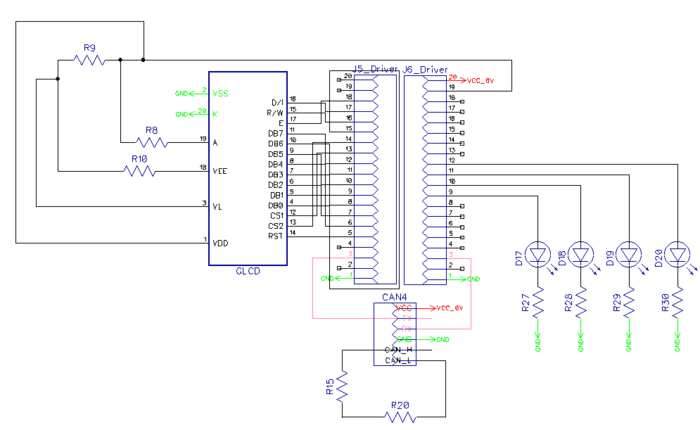
PCB Schematic
PCB Design
CAN Communication
We use controller area network to broadcast data between the 4 nodes. All nodes are connected to each other through a physically conventional two wire bus. The wires are a twisted pair with 120 Ω resistors at each ends of the bus. 1s and 0s are transmitted as CAN High(0V difference) and Can Low(2v difference). A CAN frame has the following contents:
- Data Length Code (4bits)
- Remote Transmission Request.
- ID extend bit.
- Message ID (11 bit or 29 bit)
- Data bytes( depends on DLC)
- CRC
Arbitration: No two nodes will transmit at the same time because if arbitration. A lower Message-ID has a Higher priority on the CAN bus since 0 is the dominant bit.
Bit Stuffing: CAN bus stuffs extra bits when a long chain of multiple 1's or 0's occur to improve CAN integrity.
| Sr. No | Message ID | Message function | Receivers |
|---|---|---|---|
| Driver Controller | |||
| 1 | 300 | speed and steering direction for the motor. | Motor |
| 2 | 310 | Destination reached | Sensor |
| Sensor Controller | |||
| 1 | 200 | Sensor sonars from front, back, left ,right sensor | Driver |
| Motor Controller | |||
| 8 | 700 | motor speed, motor direction | Driver |
| Geo and Bridge Controller | |||
| 1 | 400 | Bearing, Heading and Distance | Driver |
| Debug messages | |||
| 1 | 851 | Driver Debug | SENSOR,MOTOR,GEO_AND_BRIDGE |
| 1 | 811 | Motor Debug | SENSOR,MOTOR,GEO_AND_BRIDGE |
| 1 | 801 | Sensor Debug | SENSOR,MOTOR,GEO_AND_BRIDGE |
Hardware Design
DBC File
Sensor ECU
Hardware Design
Sensor Controller Schematic
Board Pin Connections
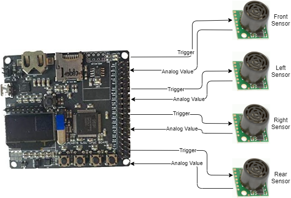
Sensors are interfaced with combination of GPIO, ADC Pins on SJTWo board. Below is the descriptive pin layout:
Software Design
The sensor node mainly does two activity viz. 1) Read sensor values, 2) Transmit obstacle distance over CAN bus. Both of these activities happen in a 20Hz periodic callback.
1. Read Sensor Values
2. Transmit obstacle distance over CAN bus:
Technical Challenges
Neighboring Sensor Interference:
Frequent noisy measurements:
Motor ECU
Hardware Design
The motor node(SJ-2) interfaces primarily interfaces with:
All these three components have 3 pins each. The functionalities of these pins are mentioned in the table below.
Software Design
Technical Challenges
Geographical And Bridge Controller
Repository link for Geo Controller
Hardware Design
Software Design
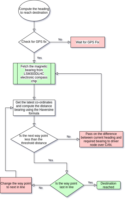
The periodic scheduler for Geo Controller Node does the following functionalities:
- In 10Hz periodic callback:
- gps__update() : Fetch GPS data from GPS controller.
- geo_compass__periodic_send() : Reads the Magnetometer and accelerometer values from Compass controller and convert those to current heading data.
- In 100Hz periodic callback:
- bluetooth__run_once() : Send specified data to android application via Bluetooth.
The GEO controller is divided into 5 parts.
- The current location of the car is determined using the GPS.
- The current magnetic heading of car is determined using the on board compass.
- The way point calculation determines the nearest way point continuously by computing the distance using Haversine formula and current location using GPS.
- The heading is also computed using the Haversine formula and the difference between the actual and required is sent over the CAN bus for heading correction.
- Alternatively, once the car is within the threshold distance, next way point is selected and the car heads to the next way point.
Technical Challenges
Driver Node
https://gitlab.com/nimit.patel/roadster/-/tree/Main/Driver_Node
Hardware Design
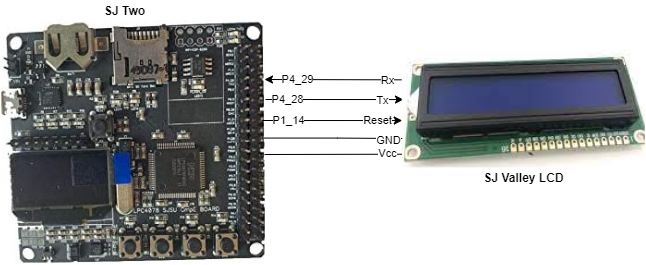
The Driver Node has one peripheral connected to it and that is the LCD screen.
Software Design
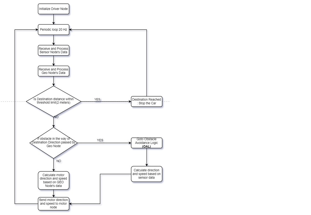
The driver node controls the logic of steering the car in the right direction based on the data received from the Sensor and Geo Nodes. The following flowchart describes that process.
- Driver Node Flow Chart
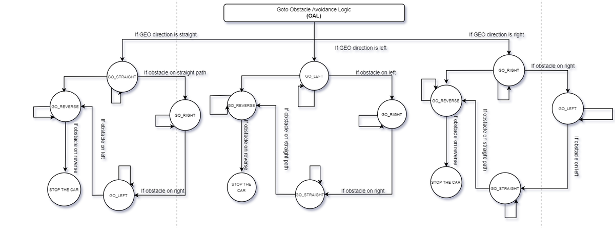
In case there are obstacles in the path where the car wants to move to, the following obstacle avoid logic would kick in.
- Driver Node Obstacle Avoidance Logic
The work in the Driver Node is done using two different periodic tasks. Here is a description of those periodic tasks and what they do.
- 1 Hz Loop:
- Transmit debug messages over the CAN bus
- Transmit messages on the LCD
- Transmit destination reached flag over the CAN Bus
- 20 Hz Loop:
- Receive Sensor Data
- Receive Geo Data
- Process and Transmit Data(Motor Direction and Speed) to Motor Node
- LCD Interface
The LCD interface on the Driver is used to print some important information about the car. This is what it prints.
- Car Speed
- Distance from the Destination
- Car State (Car Stopped from the App, Car Moving, Destination Reached)
Technical Challenges
- The Driver Node did not have much hardware interfaced on it apart from LCD. So from the hardware side there were no technical challenges. On the software front as well there were not many challenges as unit tests helped debug most of the issues then and there.
- We initially used GLCD which was configured via GPIOs and it was working perfectly. Hence we created our PCB as per this LCD. But, while testing our car with various speeds and PID logic, it got toppled and damaged the LCD. So, we had to change to SJ Valley LCD, which was configured via the UART interface, at the last moment. So, we used the same location on the PCB to place the LCD and soldered wires below PCB. Hence, this correction was not visible on our end product.
Mobile Application
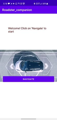
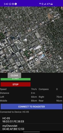
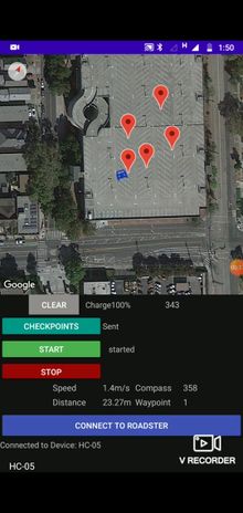
Gitlab We created a lightweight mobile app to navigate our car, It can communicate with the car via Bluetooth and is capable of sending Destination co-ordinates along with checkpoints. Receive and Update live location on Google Maps, send Start, Stop and Clear commands, Receive and Display Debug Data.
User Interface
The app has minimal buttons on the same screen as Google Maps View to confirm the cars current state and location before sending the commands.
       connect_Btn.setOnClickListener(new View.OnClickListener() {
           @Override
           public void onClick(View v) {
               listPairedDevices(v);
           }
       });
       clear.setOnClickListener(new View.OnClickListener() {
           @Override
           public void onClick(View v) {
               try {
                   if(!state) {
                       mConnectedThread.write("--,\n");
                       mMap.clear();
                       checkpoints.clear();
                       sending_status.setText("Waiting");
                   }
                   else{
                       Toast.makeText(getApplicationContext(),"Stop the car First",Toast.LENGTH_SHORT).show();
                   }
               }
               catch (Exception e)
               {
                   Toast.makeText(getApplicationContext(),"Connect to Roadster First",Toast.LENGTH_SHORT).show();
               }
           }
       });
       stop.setOnClickListener(new View.OnClickListener() {
           @Override
           public void onClick(View v) {
               try {
                   mConnectedThread.write("!!,\n");
                   state=false;
                   move_camera=false;
                   car_status.setText("   stopped");
               }
               catch (Exception e)
               {
                   Toast.makeText(getApplicationContext(),"Connect to Roadster First",Toast.LENGTH_SHORT).show();
               }
           }
       });
       start.setOnClickListener(new View.OnClickListener() {
           @Override
           public void onClick(View v) {
               try {
                   mConnectedThread.write("##,\n");
                   state=true;
                   move_camera=true;
                   car_status.setText("   started");
               }
               catch (Exception e)
               {
                   Toast.makeText(getApplicationContext(),"Connect to Roadster First",Toast.LENGTH_SHORT).show();
               }
           }
       });
       send_cpts.setOnClickListener(new View.OnClickListener() {
           @Override
           public void onClick(View v) {
               try {
                   sending_status.setText("....");
               for(int i=0;i<checkpoints.size();i++) {
                   String cpt="GPS,"+checkpoints.get(i).latitude+","+checkpoints.get(i).longitude+"\n";
                   mConnectedThread.write(cpt);
               }
               sending_status.setText("Sent");
               }
               catch (Exception e)
               {
                   Toast.makeText(getApplicationContext(),"Connect to Roadster First",Toast.LENGTH_SHORT).show();
               }
           }
       });
Software Design
This app has mainly two activities, The main activity and maps activity.
Maps Activity
This is the only functional activity for the app and is responsible for the Google Maps and Bluetooth related Tasks. User can also dynamically select multiple checkpoints and send them to the bridge node. This is achieved using java vector and OnMapclickListener setup to read each marker placed by the user.
mMap.setOnMapClickListener(new GoogleMap.OnMapClickListener() {
           @Override
           public void onMapClick(LatLng latLng) {
               int precision = (int) Math.pow(10,6);
               double new_latitude = (double)((int)(precision*latLng.latitude))/precision;
               double new_longitude = (double)((int)(precision*latLng.longitude))/precision;
               LatLng myloc = new LatLng(latLng.latitude, latLng.longitude);
               mMap.addMarker(new MarkerOptions().position(myloc).title("Destination"));
               mMap.moveCamera(CameraUpdateFactory.newLatLngZoom(myloc,20));
               checkpoints.add(new LatLng(new_latitude,new_longitude));
               destination_coordinates = "GPS," + new_latitude + "," + new_longitude +"\n";
           }
       });
Bluetooth
The Bluetooth connection is initially set up by reading the id and MAC addresses of the selected device, The available devices are displayed on a listView under the connect button. Once the socket is established, Bluetooth module provides read() and write() API used to communicate.
           if(!mBTAdapter.isEnabled()) {
               Toast.makeText(getBaseContext(), "Bluetooth not on", Toast.LENGTH_SHORT).show();
               return;
           }
           mBluetoothStatus.setText("Connecting...");
           // Get the device MAC address, which is the last 17 chars in the View
           String info = ((TextView) v).getText().toString();
           final String address = info.substring(info.length() - 17);
           final String name = info.substring(0,info.length() - 17);
           new Thread()
           {
               public void run() {
                   boolean fail = false;
                   BluetoothDevice device = mBTAdapter.getRemoteDevice(address);
                   try {
                       mBTSocket = createBluetoothSocket(device);
                   } catch (IOException e) {
                       fail = true;
                       Toast.makeText(getBaseContext(), "Socket creation failed", Toast.LENGTH_SHORT).show();
                   }
                   // Establish the Bluetooth socket connection.
                   try {
                       mBTSocket.connect();
                   } catch (IOException e) {
                       try {
                           fail = true;
                           mBTSocket.close();
                           mHandler.obtainMessage(CONNECTING_STATUS, -1, -1)
                                   .sendToTarget();
                       } catch (IOException e2) {
                           Toast.makeText(getBaseContext(), "Socket creation failed", Toast.LENGTH_SHORT).show();
                       }
                   }
                   if(fail == false) {
                       mConnectedThread = new ConnectedThread(mBTSocket);
                       mConnectedThread.start();
                       mHandler.obtainMessage(CONNECTING_STATUS, 1, -1, name)
                               .sendToTarget();
                   }
The Bridge node sends data in string format with end of line chars, The Bluetooth handler concatenates the received data and waits for the "end of line" before trying to parse it. Below is the code snippet that parses the incoming stream with location and debug data sent by the bridge node.
                   if(readMessage.indexOf("\n")>0) {
                       message = new StringTokenizer(readMessage, "\n");
                       StringTokenizer st;
                       while (message.hasMoreTokens()) {
                           st = null;
                           received_line = message.nextToken();
                           st = new StringTokenizer(received_line, ",");
                           try {
                               read = st.nextToken();
                           } catch (Exception e) {
                               continue;
                           }
                           if (read.compareTo("GPS") == 0) {
                               try {
                                   LatLng current_location = new LatLng(Double.parseDouble(st.nextToken()), Double.parseDouble(st.nextToken()));
                                   waypoint.setText(st.nextToken("\n").replace(",", ""));
                                   prev.remove();
                                   prev = mMap.addMarker(new
                                          MarkerOptions().position(current_location).anchor(0.5f,0.5f).rotation(compass_value).title("Roadster")
                                          .icon(BitmapFromVector(getApplicationContext(), R.drawable.ic_baseline_directions_car_filled_24)));
                            if (state || init) {
                                       mMap.moveCamera(CameraUpdateFactory.newLatLng(current_location));
                                       if (current_location.latitude != 0) init = false;
                                   }
                               } catch (Exception e) {
                               }
                           } else if (read.compareTo("speed") == 0) {
                               try {
                                   speed.setText(st.nextToken("\n").replace(",", "") + "m/s");
                               } catch (Exception e) {
                               }
                           } else if (read.compareTo("sens") == 0) {
                               try {
                                   left.setText(st.nextToken() + "cm");
                                   right.setText(st.nextToken() + "cm");
                                   center.setText(st.nextToken() + "cm");
                                   back.setText(st.nextToken("\n").replace(",", "") + "cm");
                               } catch (Exception e) {
                               }
                           } else if (read.compareTo("comp") == 0) {
                               try {
                                   compass.setText(st.nextToken());
                                   String compass_s=st.nextToken("\n").replace(",", "");
                                   compass_raw.setText(compass_s);
                                   compass_value =Integer.parseInt(compass_s);
                                   prev.setAnchor(0.5f,0.5f);
                                   prev.setRotation(compass_value);
                               } catch (Exception e) {
                               }
                           } else if (read.compareTo("dist") == 0) {
                               try {
                                   String dis=st.nextToken("\n").replace(",", "");
                                   distance.setText(dis+"m");
                                   //int prog=(int)Float.parseFloat(dis)%200;
                                   //progress.setProgress(prog);
                               } catch (Exception e) {
                               }
                           } else if (read.compareTo("mot") == 0) {
                               try {
                                   rps.setText(st.nextToken());
                                   pwm.setText(st.nextToken("\n").replace(",", ""));
                               } catch (Exception e) {
                               }
                           }
                           else if(read.compareTo("bat")==0){
                               try{
                                   battery.setText(st.nextToken("\n").replace(",", "")+"%");
                               }catch (Exception e){
                               }
                           }
                      }
                       readMessage="";
Technical Challenges
Given no experience in Android Development, we had to start from the basics about the activities, message passing etc. The initial challenge was to understand the google maps API and generate the API key to access google cloud to implement the map view and markers. Implementing Bluetooth communication required scanning the list of paired devices and acquire the MAC address required to open a socket using the provided API. Fortunately, there are many example implementations to go through. We decided to use a similar line buffer that is used in the Geo node to read the debug data sent from the app, this helped solve the challenge of parsing the group of variables sent by the bridge node by reading from the CAN bus.
Conclusion
- Embedded project are generally single board projects. The mandatory use of CAN bus required a great deal of collaboration, where all board are interdependent and the system design should be robust to make it work every single time, the car is used for its intended purpose.
- Unit testing helps in early phase of the project, where the hardware setup is not ready yet, but one needs to start coding to get ahead of the curve and start building logic. This helps in troubleshooting the hardware as well.
Project Video
Project Source Code
Repository link for Autonomous RC Car Repository for Android App
Advise for Future Students
- Get the hardware modules and test the same with SJ2 (Before the Mid Semester exams). Once this is done, create a PCB and mount devices and then start the extensive software testing. Considering the car is moving object, temporary connections over bread board and zero PCB might work, but reliability will remain a doubt at the back of the head. Eliminate the same by creating the PCB early. You might even want to iterate to a second PCB, once you are a few weeks into testing and want to change amend previous mistakes/improve existing layout and placements. The time and effort this will save is worth it.
- Once the hardware is nearing its completion, the Mobile app should be ready in its rudimentary form. Having a hand held debug device is more useful, compared to using PCAN dongle which is great for static testing.
- The software will take multiple iteration by testing your car in various field scenarios. This is not a project which can be completed a night before demo. Keep a healthy amount of time for testing.
- The sole working power socket available in university outside of the university buildings is available on the top floor of the tenth street car garage. This is especially useful when testing in field.
Acknowledgement
- Building a hardware project without the availability of a electronics lab of the university which had been shut, due to COVID-19 pandemic tested our resourcefulness to our extremes.Considering the remote nature of course work, resource availability in any shape or form from university was sadly non existent. All the team members should be appreciated for their unwavering enthusiasm to make this a success story.
- Preet's advice for buying quality hardware parts should be followed to the line.
References
http://socialledge.com/sjsu/index.php/Industrial_Application_using_CAN_Bus
