F19: Infinity Mirror
Contents
- 1 Infinity Mirror
- 2 Abstract
- 3 Introduction & Objectives
- 4 Team Members & Technical Responsibilities
- 5 Administrative Responsibilities
- 6 Team Deliverables Schedule
- 7 Bill of Materials (General Parts)
- 8 Printed Circuit Board
- 9 3D printing models
- 10 RGB LED Matrix
- 11 MP3 Decoder
- 12 Sensors Interface
- 13 OLED Display
- 14 Bluetooth Interface
- 15 Testing and Technical Challenges
- 16 Suggestions for Future Students
- 17 Conclusion
- 18 Project Video
- 19 Project Source Code
- 20 References
Infinity Mirror
Abstract
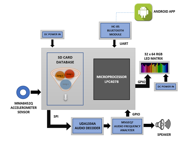
In this project our main aim to build an embedded system based Music System that also displays 7 bands of frequency spectrum on an (32 x 64) LED display. The MP3 system plays music through a speaker interfaced with the board. It deals with the convergence of various services such as gesture recognition, audio decoding, audio saving and retrieving and audio frequency band visualisation etc. This project consists of 'Audio Codec', 'RGB LED Matrix' and 'HC-05' along with some other onboard features like 'Gesture detection', 'Ambient Light Sensing' and 'OLED Display' with SJ-two Launch pad.
Introduction & Objectives
The key features support by the system are real-time Gesture recognition & trigger actions in player and display audio Spectrum on LED matrix:
1. Determine the actions of air gesture based on the input received or through a manual key selection of songs from the Songs List (In this prototype, search for the response for recognised gesture from the database & perform actions to other peripherals.)
2. In response, retrieve the data from the SD Card & communicate to the audio decoder for audio streaming.
3. Onboard display will show current playing song information and LED Matrix will show audio spectrum patterns using mirroring Visualisation effect.
4. Interacting with HC-05 bluetooth for communicating with Mobile App.
5. A Game related to Audio and Gesture detection - a ball smasher game in which ball will be randomly created on the LED matrix based on the Audio Frequency which will be smashed by collecting Gesture in that particular direction and display the score on the OLED Display.
Project Objectives
     1. Audio Codec - Interacting with Audio Codec for getting the sound samples & generating sound signals from the device
     2. Gesture Sensor - Detects the Hand Gesture and send the detected gesture to LED Matrix to navigate LED's.
     3. SD Card - Audio data or mp3 files will be retrieved from the SD card based on the user selection.
     4. Audio Decoder - Intelligently processing the audio data using audio decoder and sent to the LED Matrix to display spectrum patterns.
     5. Bluetooth HC-05 - Interfaces the system using Bluetooth to an Android application.
Team Objectives
     1. Learn each and every module as much as possible, in order to develop an overall product.
     2. Understand the proper use of queues and semaphores in order to send/receive the data between multiple tasks.
     3. Document and track all the bugs encountered during development and learn to update git repo after every fix.
Team Members & Technical Responsibilities
- MP3 Audio Encoder/Decoder
- Bluetooth Communication
- Interfacing of LED Matrix and driver
- Implementing game logic
- Implementing spectrum band logic and MP3 modes (pause, next, previous) on LED
- Interfacing of Gesture & Accelerometer Sensors
- Android & Web Application
- OLED Interfacing & UI Designing
- Hardware PCB Integration
- Testing
Administrative Responsibilities
| Administrative Roles | ||||
|---|---|---|---|---|
|
Aakash Chitroda | |||
|
Niket Naidu | |||
|
Vidushi Jain | |||
|
Vidushi Jain | |||
|
Ganesh Ram | |||
Team Deliverables Schedule
| WEEK |
START DATE |
END DATE |
TASK DETAILS |
STATUS |
|---|---|---|---|---|
| 1 | 15 Oct 2019 | 22 Oct 2019 |
|
Completed Completed Completed Completed |
| 2 | 23 Oct 2019 | 29 Oct 2019 |
|
Completed Completed Completed Completed Completed |
| 3 | 30 Oct 2019 | 5 Nov 2019 |
|
Completed Completed Completed Completed Completed Completed |
| 4 | 6 Nov 2019 | 12 Nov 2019 |
|
Completed Completed Completed Completed Completed Completed |
| 5 | 13 Nov 2019 | 19 Nov 2019 |
|
TBD TBD TBD Completed TBD TBD TBD |
| 6 | 20 Nov 2019 | 26 Nov 2019 |
|
TBD TBD TBD TBD TBD TBD TBD |
| 8 | 27 Nov 2019 | 3 Dec 2019 |
|
TBD TBD TBD TBD TBD |
| 9 | 4 Dec 2019 | 10 Dec 2019 |
|
TBD TBD TBD TBD TBD |
| 10 | 11 Dec 2019 | 17 Dec 2019 |
|
TBD TBD TBD TBD TBD |
| 11 | 18 Dec 2019 |
|
TBD TBD |
Bill of Materials (General Parts)
| PART NAME |
PART MODEL & SOURCE |
QUANTITY |
COST PER UNIT (USD) |
|---|---|---|---|
|
|
|
|
|
|
| |
|
|
| |
|
|
| |
|
|
| |
|
|
|
|
|
|
|
|
|
|
|
Printed Circuit Board
Design And Architecture
Power Section
Fabrication
3D printing models
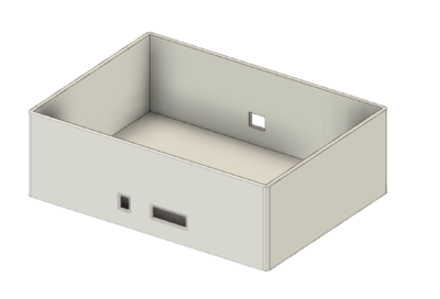
We used a 3D mount model to place our PCB Board.
RGB LED Matrix
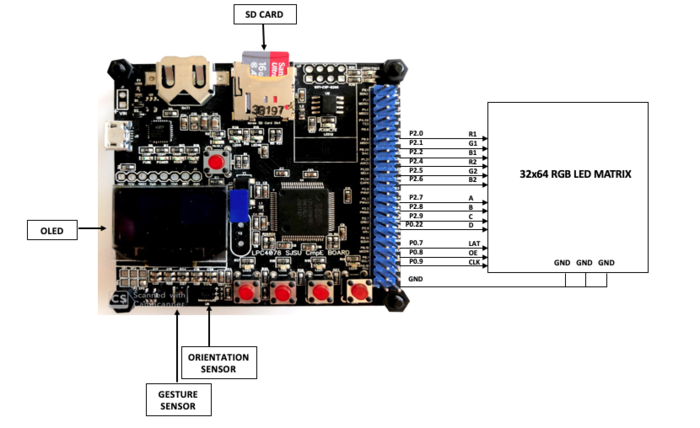
A 32 x 64 RGB LED Matrix will be powered up through a 5V/4A DC adapter and is interfaced with the board to display the frequency bands and other relevant messages such as "Next", "Previous" and "Pause". Only the INPUT IDC connector will be used because we are not cascading multiple matrices. The matrix has 2 planes (upper and lower), both of which will be programmed separately. In order to set RGB color data for each pixel in plane 1 (top half of the display) we use R1, G1 and B1 pins and for plane 2 we use R2, G2 and B2. By setting and resetting the CLOCK pulse, color data is set for every pixel in the row. Then the LATCH is set to mark end of the row and reset to move to next row. All of these steps are repeated at very less time intervals so that the human eye perceives it as one complete frame (Persistence of Vision).
Below is the description of the pins:
- R1 -> Sets upper panel's Red data
- G1 -> Sets upper panel's Green data
- B1 -> Sets upper panel's Blue data
- R2 -> Sets lower panel's Red data
- G2 -> Sets lower panel's Green data
- B2 -> Sets lower panel's Blue data
- A -> Sets row bit 0
- B -> Sets row bit 1
- C -> Sets row bit 2
- D -> Sets row bit 3
- CLK (Clock) -> Set to access each pixel
- LAT (Latch) -> Set to mark comletion of one row
- nOE (Output Enable) -> Set to switch the LEDs off when transitioning from one row to the next
- GND -> Ground pins to be connected with board's GND.
LED Matrix Code
GitLab link to LED Matrix Code
Hardware Design
The hardware involves 5V/4A DC power supply adapter, barrel jack connectors and IDC cables to power up the LED matrix and communicate with the board. Below is the pin interfacing diagram.
Software Design
1. Fruit Fury - Game mode There are 3 tasks created here. Task 1:
- Display the game's title screen. On pressing the onboard switch, game begins.
- Also used to display game over screen.
Task 2:
- Enter into game mode to play the game.
- Read accelerometer values and render game frame.
- On detecting the player's board movement, compare it with fruit's location and proceed further to update score, lives and smash effects.
Game rules 1. Game comprises of 3 levels and 5 lives in total. 2. Primary objective is to tilt the board to the direction where the fruit appears on the LED matrix. 3. Score increases for smashing each fruit. 4. Level 2 has bombs and avoid smashing one. 5. Level 3 is faster so make sure you tune up your reflexes. 'Bonus' 1. Streaks are rewarding. Smash 10 fruits straight up to win an extra life. 2. Look out for star fruits. Hit them to gain +2 points.
Choose your song to take all the inspiration you can and start smashing!
Music mode Press the button to switch to enjoy the music-only mode. Graceful audio spectrum bands are displayed on the LED matrix that dance to the tune of your chosen song. A display is prompted to the user whenever music is paused or changed to next or previous song.
Implementation
This section includes implementation, but again, not the details, just the high level. For example, you can list the steps it takes to communicate over a sensor, or the steps needed to write a page of memory onto SPI Flash. You can include sub-sections for each of your component implementation.
MP3 Decoder
=MP3 Decoder Code
GitLab link to MP3 Decoder Code
Hardware Design
Software Design
Implementation
Sensors Interface
Sensor Code
Hardware Design
Software Design
Implementation
OLED Display
OLED Display Code
GitLab link to OLED Display Code
Hardware Design
Software Design
Implementation
Bluetooth Interface
Bluetooth Code
Hardware Design
Software Design
Implementation
Testing and Technical Challenges
1. RGB LED Matrix
a) Getting control of the matrix was challenging as it needs to follow specific sequence of pin enabling/disabling at appropriate timing.
b) Setting right delays to avoid flickers and get smooth transitioning between frames.
c) Fixing high CPU utilization.
d) Designing elements of the game (title screen and fruit objects).
Suggestions for Future Students
1. RGB LED Matrix
- Focus on writing simple driver to get control of 1 pixel at a targeted location and then use appropriate loops to light up entire row/column.
- Try with minimum / no delays, print tick counts and then come up with meaningful delay numbers.
- Optimize the code (minimum delays, avoiding repetitive function calls etc.) to bring down the CPU usage level.
- Use the link mentioned in the reference to draw the desired elements and generate the matrix.
Conclusion
Conclude your project here. You can recap your testing and problems. You should address the "so what" part here to indicate what you ultimately learnt from this project. How has this project increased your knowledge?
Project Video
Upload a video of your project and post the link here.
Project Source Code
- Git Project Link: [1]
References
Acknowledgement
We would like to thank professor Preet for giving us the opportunity to incorporate the theory learnt into practical model and supporting us whenever needed. Availability of slack channel and weekly reviews ensured us to clarify bottlenecks in the project, keep things organized and track progress of each tasks. We would also extend our gratitude towards ISA members who have taken their time in clearing our queries throughout the course.
