S16: OpenSJ Bluz
Contents
- 1 Grading Criteria
- 2 OpenSJ Bluz
- 3 Abstract
- 4 Objectives & Introduction
- 5 Schedule
- 6 Parts List & Cost
- 7 Design & Implementation
- 7.1 Hardware Design
- 7.2 Hardware Interface
- 7.3 Software Design
- 7.4 Implementation
- 7.4.1 BLE Advertising Initialization
- 7.4.2 Nordic UART Service Implementation
- 7.4.3 Brief description of important code lines in Nordic BLE module
- 7.4.4 Software UART Configuration
- 7.4.5 Keil Projects Configuration for the SEGGER Debugger
- 7.4.6 Programming Bluefruit module using nRFgo Studio
- 7.4.7 Generating custom BLE services using Bluetooth Developer Studio(BDS)
- 7.4.8 Benefit of having an external 32kHz crystal
- 7.4.9 Building Android Application
- 8 Testing & Technical Challenges
- 9 Conclusion
- 10 References
Grading Criteria
- How well is Software & Hardware Design described?
- How well can this report be used to reproduce this project?
- Code Quality
- Overall Report Quality:
- Software Block Diagrams
- Hardware Block Diagrams
- Schematic Quality
- Quality of technical challenges and solutions adopted.
OpenSJ Bluz
Real-time system for acquiring, monitoring and distributing miscellaneous sensor data.
Abstract
OpenSJ Bluz - A project which aims to develop a system to collect, analyze and distribute sensor data in real-time.
With the rapid adoption of IoT, everyone is looking for ways to get their sensors connected. There is a rising demand for all sensor data to be available in real-time across the internet. The proliferation of smart phones has given access to highly mobile computational power. OpenSJ Bluz, brings together next generation of sensor data gathering, analysis and distribution to the classroom and beyond, today. Gone are the days when sensors needed to be connected using wired UARTS and when data transmission meant copying csv and binary dump files.
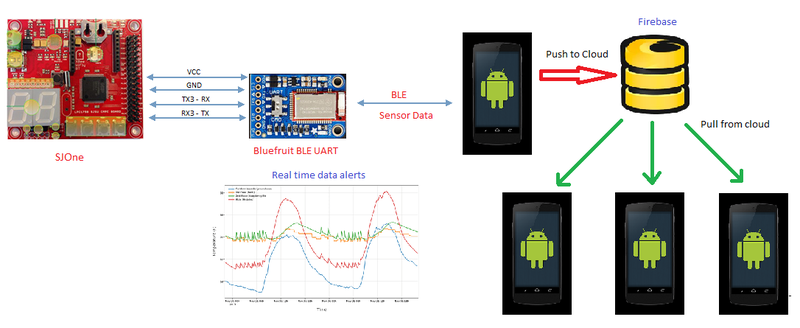
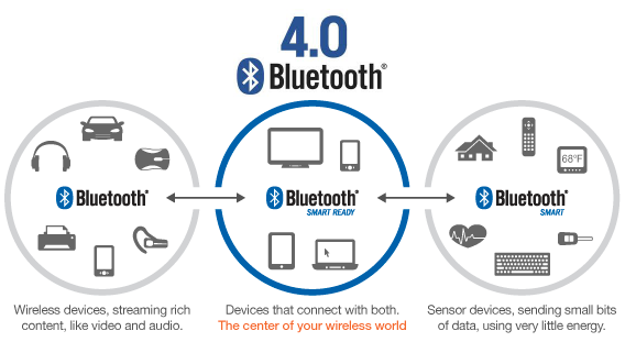
OpenSJ Bluz, uses the latest wireless technology - Bluetooth Smart (4.0) also known as Bluetooth Low Energy Or BLE to acquire data from sensors connected to the SJOne board. Data is acquired in realtime using FreeRTOS - a Real-time operating system. This data is then transmitted to a Bluetooth LE enabled smartphone which analyzes the data and gives immediate feedback. The data is then pushed to the cloud and distributed to interested and authenticated nodes using a real-time database called FireBase. The connected nodes then further analyze and process this data.
This makes OpenSJ Bluez an end-to-end real-time data collection, analysis and distribution system.
Objectives & Introduction
Objectives
The main objectives of this project are classified into 3 groups. They are :-
- Acquiring data from sensors
- Use FreeRTOS API's to interface with IMU sensor
- Use FreeRTOS API's to interface with Light sensor
- Use FreeRTOS API's to setup UART and communicate with BLE wireless module
- Bluetooth LE interfacing
- Setup Adafruit BLE wireless module
- Generate connection profile
- Setup and configure BLE services, characteristics and their descriptors
- Setup and configure android device to connect with wireless module
- Implement BLE interfaces for configured services, characteristics and descriptors
- Scan for BLE device and connect to device of interest
- Pull in sensor readings
- Data analysis and distribution
- Generate immediate feedback visualization for sensor data
- Implement push to cloud framework
- Implement pull from cloud framework
- Generate visualization for pulled sensor data
Introduction
There is a huge demand for real-time sensor data streaming over the internet. This project aims to realize this using the SJOne board and aims to make a versatile system which can be used as the basis for a full fledged sensor data collection, analysis and storage system. Such a system should be able to support many different producer and consumer nodes. In this project we are using the SJOne board and an android smartphone, but the system should be extensible to any device that can communicate sensor data to any kind of an internet enabled smart phone.
Overview
- Bluetooth Low Energy(BLE) is powerful technology and now it’s available for everyone because it is inexpensive and less complex than it’s older brother, Bluetooth classic.
- Bluetooth Low Energy is incredibly flexible; anyone can create a custom profile for specific applications and still adhere to the Bluetooth SIG.
Let’s first talk basic terminology and then go into details:
- Master (or “central“) devices scan for other devices. Usually, the master is a smartphone/tablet/PC (Bluetooth Smart Device).
- Slave (or “peripheral“) devices advertise and wait for connections. Usually, the slave is a small device like a fitness tracker or a smartwatch.
- Client devices access remote resources over a BLE link using the GATT protocol. Usually, the master is also the client but that is not required.
- Server devices have a local database and access control methods, and provide resources to the remote client. Usually, the slave is also the server (again, that is not required)
- A device can switch between a Master and Slave but it cannot be both at the same time.
- A device can be a Server and Client at the same time.
- You can use read, write, notify, or indicate operations to move data between the client and the server.
- Read and write operations are requested by the client and the server responds (or acknowledges).
- Notify and indicate operations are enabled by the client but initiated by the server, providing a way to push data to the client.
- Notifications are unacknowledged, while indications are acknowledged. Notifications are therefore faster, but less reliable.
Master vs Slave
- So what is the difference between a master and a slave? First let me remind you that a master and a slave is not interchangeable with client/server.
- A master (or Central) is the BLE device that initiates an outgoing connection request to an advertising peripheral device.
- A slave (or Peripheral) is the BLE device which accepts an incoming connection request after advertising.
- A slave can only be connected to one master, but a master can be connected to multiple slaves. In the smartwatch example, your iPhone can theoretically connect to multiple smartwatches at the same time. However, your smartwatch can only ever connect to one smartphone at a time.
- There is no limit in the Bluetooth SIG on the number of slaves a master can connect to. Generally this will be limited by the BLE technology or Bluetooth stack you use.
Client vs Server
Let’s move on to the differences between a GATT server and a GATT client
- A GATT client is a device which accesses data on the remote GATT server via read, write, notify, or indicate operations.
- A GATT server is a device which stores data locally and provides data access methods to a remote GATT client.
You can easily see that it is possible for a device to be a GATT server and a GATT client at the same time. While it is most common for the slave (peripheral) device to be the GATT server and the master (central) device to be the GATT client, this is not required. The GATT functionality of a device is logically separate from the master/slave role. The master/slave roles control how the BLE radio connection is managed, and the client/server roles are dictated by the storage and flow of data.
Android
Android is a mobile operating system (OS) currently developed by Google, based on the Linux kernel and designed primarily for touchscreen mobile devices such as smartphones and tablets.
Why select android?
Android is one of the leading smartphone OS and with the introduction of BLE support, many devices now implement BLE interface and radios. Cheap cost, easy programming and easy availability were the key factors to select the android platform for this project.
Firebase
Firebase is a complete platform for building mobile and web applications. The Firebase is a scalable realtime and cloud-hosted database. Data is stored as JSON and synchronized in realtime to every connected client.
Why select Firebase
To keep the system as near to real-time as possible, we faced the challenge of selecting a fast (real-time) database. Preliminary analysis led us to believe that firebase would be the ideal database since it provides us with authentication and hosting services for iOS, Android, and Web; in addition to serving our primary purpose of being realtime and scalable.
Team Members & Responsibilities
- Dhruv Kakadiya
- Surojit Sengupta
Schedule
Show a simple table or figures that show your scheduled as planned before you started working on the project. Then in another table column, write down the actual schedule so that readers can see the planned vs. actual goals. The point of the schedule is for readers to assess how to pace themselves if they are doing a similar project.
Team Schedule
| SI No. | Start Date | End Date | Task | Team Member | Status | Actual Completion Date |
|---|---|---|---|---|---|---|
| 1 | 03/12/2016 | 03/22/2016 |
|
- | Completed | 03/21/2016 |
| 2 | 03/22/2016 | 03/27/2016 | Following up on hardware components procurement through team discussions, PCB design | Dhruv | Completed | 03/26/2016 |
| 3 | 03/27/2016 | 03/29/2016 | Finding out a way to program Bluefruit Module using SW(serial wire) interface. | Dhruv | Completed | 03/30/2016 |
| 4 | 03/29/2016 | 04/1/2016 | Implement HRS(Heart Rate Sensor) Profile on BlueFruit Module | Dhruv, Surojit | Completed | 04/1/2016 |
| 5 | 04/1/2016 | 04/4/2016 | Implement Nordic UART Service to send and receive data from UART ( Wireless UART ) and check communication using Nordic Master Control Panel Application | Dhruv, Surojit | Completed | 04/4/2016 |
| 6 | 04/4/2016 | 04/10/2016 | Create individual BLE profile for each sensor (Accelerometer, Temperature, Light etc.) | Dhruv, Surojit | Completed | 04/12/2016 |
| 7 | 04/10/2016 | 04/25/2016 | Create simple BLE Android application to receive sensor data in appropriate BLE service | Dhruv, Surojit | Completed | 04/30/2016 |
| 8 | 04/25/2016 | 04/30/2016 | Create user defined GATT services and broadcast individual sensor data in individual services and plot real time graphs on Android | Surojit | Completed | 05/10/2016 |
| 9 | 04/30/2016 | 05/10/2016 | PCB and Firmware testing and debugging, Pushing all data to the cloud | Dhruv, Surojit | Complete | 05/20/2016 |
Parts List & Cost
Give a simple list of the cost of your project broken down by components. Do not write long stories here.
| Item# | Part Desciption | Vendor | Qty | Cost |
|---|---|---|---|---|
| 1 | Bluefruit UART BLE Module | Adafruit | 1 | $23.75 |
| 2 | SJOne board | CmpE Department | 1 | $80 |
| 3 | nRF51DK | Mouser | 1 | $39 |
| Total Cost | $150 |
Design & Implementation
The design section can go over your hardware and software design. Organize this section using sub-sections that go over your design and implementation.
Hardware Design
Discuss your hardware design here. Show detailed schematics, and the interface here.
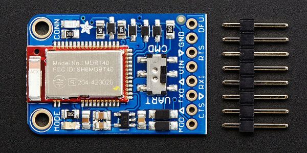
Technical Specifications for Bluefruit BLE module
- Nordic nRF51822 - ARM Cortex M0 core running at 16MHz
- 256KB flash memory
- 32KB SRAM
- Peak current draw <20mA (radio actively transmitting/receiving)
- Transport: UART typically @ 9600 baud with HW flow control (Configurable)
- 5V-safe inputs
- On-board 3.3V voltage regulation
- Bootloader with support for safe OTA firmware updates
- Supports Central and Peripheral mode
- Supports Bluetooth Smart protocol stacks
- On air compatible with nRF24L series
Front side breakouts
Power pins
- VIN - This is the power supply for the module, supply with 3.3-16V power supply input. This will be regulated down to 3.3V to run the chip
- GND - The common/GND pin for power and logic
UART pins
- TXO - This is the UART Transmit pin out of the breakout (Bluefruit LE --> SJOne), it's at 3.3V logic level.
- RXI - This is the UART Receive pin into the breakout (SJOne--> Bluefruit LE). This has a logic level shifter on it, you can use 3-5V logic.
- CTS - Clear to Send hardware flow control pin into the the breakou (SJOne--> Bluefruit LE). Use this pin to tell the Bluefruit that it can send data back to the SJOne over the TXO pin. This pin is pulled high by default and must be set to ground in order to enable data transfer out! If you do not need hardware flow control, tie this pin to ground it is a level shifted pin, you can use 3-5V logic
- RTS - Read to Send flow control pin out of the module (Bluefruit LE --> SJOne). This pin will be low when its fine to send data to the Bluefruit. In general, at 9600 baud we haven't seen a need for this pin, but you can watch it for full flow control! This pin is 3.3V out
Other pins
- MOD - Mode Selection. The Bluefruit has two modes, Command and Data. You can keep this pin disconnected, and use the slide switch to select the mode. Or, you can control the mode by setting this pin voltage, it will override the switch setting! High = Command Mode, Low = UART/DATA mode. This pin is level shifted, you can use 3-5V logic
- DFU - Setting this pin low when you power the device up will force the Bluefruit LE module to enter a special firmware update mode to update the firmware over the air. Once the device is powered up, this pin can also be used to perform a factory reset. Wire the pin to GND for >5s until the two LEDs start to blink, then release the pin (set it to 5V or logic high) and a factory reset will be performed.
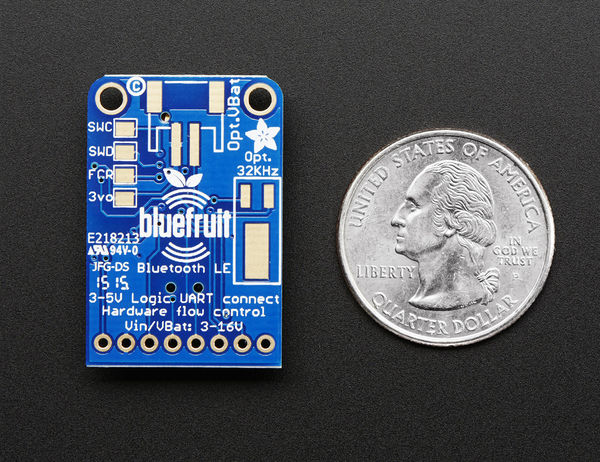
Reverse side breakouts
- Reverse side pin outs for Bluefruit module is as per below.
- Opt VBat - One can solder on a JST 2-PH connector, this will let us easily plug in a Lithium Ion or other battery pack. This connector pad is diode protected so we can use both Vin and VBat and the regulator will automatically switch to the higher voltage
- Opt. 32 KHz - It is for some funky low power work, in that case one can solder 32khz oscillator.
- SWC - This is the SWD clock pin, 3v logic.
- SWD - This is the SWD data pin, 3v logic.
- 3Vo - This is the output from the 3V regulator, for testing and also if one really need regulated 3V, up to 250mA available
- FCR - This is the factory reset pin. Tie this pad to ground while powering up the module and it will factory reset.
Hardware Interface
In this section, you can describe how your hardware communicates, such as which BUSes used. You can discuss your driver implementation here, such that the Software Design section is isolated to talk about high level workings rather than inner working of your project.
Software Design
Show your software design. For example, if you are designing an MP3 Player, show the tasks that you are using, and what they are doing at a high level. Do not show the details of the code. For example, do not show exact code, but you may show psuedocode and fragments of code. Keep in mind that you are showing DESIGN of your software, not the inner workings of it.
Needed Software tools to program nRF51822 Bluefruit module
- nRFgo Studio
- nRF51 Software Development Kit (SDKv8.0.0)
- Keil IDE
- S110 nRF51822 SoftDevice
- S110 SoftDevice programming tools
- Nordic Master Control Panel Android/iOS application
- Segger J-Link Programmer
Basic theory behind BLE GATT Profile, Services, Characteristics and UUID
The Bluetooth Core Specification defines the Generic Attribute Profile (GATT) like this:
   "The GATT Profile specifies the structure in which profile data is exchanged. This structure defines basic elements
    such as services and characteristics, used in a profile."
In other words, it is a set of rules describing how to bundle, present and transfer data using BLE.
The Bluetooth Core Specification defines a service like this:
   "A service is a collection of data and associated behaviors to accomplish a particular function or feature.
    [...] A service definition may contain […] mandatory characteristics and optional characteristics."
In other words, a service is a collection of information, like e.g. values of sensors. Bluetooth Special Interest Group (Bluetooth SIG) has predefined certain services. For example they have defined a service called Heart Rate service. The reason why they have done this is to make it easier for developers to make apps and firmware compatible with the standard Heart Rate service. However, this does not mean that you can't make your own heart rate sensor based on your own ideas and service structures. Sometimes people mistakenly assumes that since Bluetooth SIG has predefined some services they can only make applications abiding by these definitions. This is not the case. It is no problem to make custom services for your custom applications.
The Bluetooth Core Specification defines a characteristic like this:
   "A characteristic is a value used in a service along with properties and configuration information about
    how the value is accessed and information about how the value is displayed or represented."
In other words, the characteristic is where the actual values and information is presented. Security parameters, units and other metadata concerning the information are also encapsulated in the characteristics.
A UUID is an abbreviation for Universally Unique ID and you will see this abbreviation a lot in the BLE world. It is a unique number used to identify services, characteristics and descriptors, also known as attributes. These IDs are transmitted over the air so that e.g. a peripheral can inform a central what services it provides. To save transmitting air time and memory space in your nRF51 there are two kinds of UUIDs:
1) 16-bit UUID : This is energy and memory efficient, but since it only provides a relatively limited number of unique IDs there is a rule; you can only transmit the predefined Bluetooth SIG UUIDs directly over the air. Hence there is a need for a second type of UUID so you can transmit your own custom UUIDs as well.
2) 128-bit UUID : Sometimes this referred to as a vendor specific UUID. This is the type of UUID you need to use when you are making your own custom services and characteristics. It looks something like this: 4A98xxxx-1CC4-E7C1-C757-F1267DD021E8 and is called the “base UUID”'. The four x’s represent a field where you will insert your own 16-bit IDs for your custom services and characteristics and use them just like a predefined UUID. This way you can store the base UUID once in memory, forget about it, and work with 16-bit IDs as normal. You can generate base UUIDs using nRFgo Studio. It is very easy and you can look in the Help menu to learn how.
Implementation
This section includes implementation, but again, not the details, just the high level. For example, you can list the steps it takes to communicate over a sensor, or the steps needed to write a page of memory onto SPI Flash. You can include sub-sections for each of your component implementation.
- In every BLE device, there are two mandotary services implemented.
- The Generic Access service: Service UUID 0x1800. Three mandatory characteristics:
- Characteristic: Device name. UUID 0x2A00.
- Characteristic: Appearance. UUID 0x2A01.
- Characteristic: Peripheral Preferred Connection Parameters. UUID 0x2A04.
- Characteristic: Device name. UUID 0x2A00.
- The Generic Attribute service. UUID 0x1801. One optional characteristic:
- Characteristic: Service Changed. UUID 0x2A05.
- Characteristic: Service Changed. UUID 0x2A05.
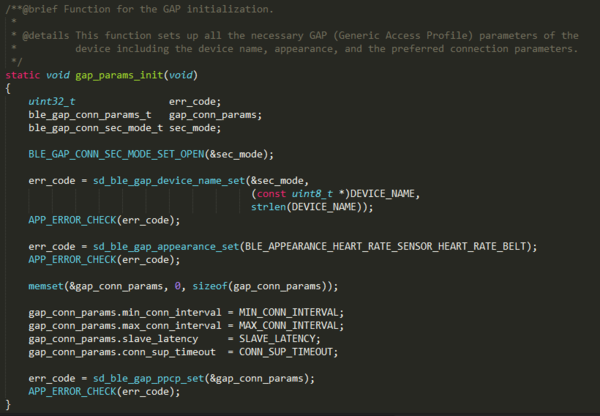
- The Generic Access Service contains general information about the device. You can recognize a characteristic holding the device name “OpenSJBluz”. The second characteristic holds the appearance value and in our case we haven't set the value to anything so it just shows 0x0000. The third characteristic holds various parameters used to establish a connection. You can recognise values from the #defines in the example called: MIN_CONN_INTERVAL, MAX_CONN_INTERVAL, SLAVE_LATENCY, and CONN_SUP_TIMEOUT. Here is a short explanation regarding these parameters.
The connection parameters for a BLE connection is a set of parameters that determine when and how the Central and a Peripheral in a link transmits data. It is always the Central that actually sets the connection parameters used, but the Peripheral can send a so-called Connection Parameter Update Request, that the Central can then accept or reject.
There are basically three different parameters:
- Connection interval: Determines how often the Central will ask for data from the Peripheral. When the Peripheral requests an update, it supplies a maximum and a minimum wanted interval. The connection interval must be between 7.5 ms and 4 s.
- Slave latency: By setting a non-zero slave latency, the Peripheral can choose to not answer when the Central asks for data up to the slave latency number of times. However, if the Peripheral has data to send, it can choose to send data at any time. This enables a peripheral to stay sleeping for a longer time, if it doesn't have data to send, but still send data fast if needed. The text book example
of such device is for example keyboard and mice, which want to be sleeping for as long as possible when there is no data to send, but still have low latency (and for the mouse: low connection interval) when needed.
- Connection supervision timeout: This timeout determines the timeout from the last data exchange till a link is considered lost. A Central will not start trying to reconnect before the timeout has passed, so if you have a device which goes in and out of range often, and you need to notice when that happens, it might make sense to have a short timeout.
Depending on which platform you're working with, there can be platform specific recommendations or requirements on these. For iOS, Apple maintains a "Bluetooth Accessory Design Guidelines" document, which among other things includes rules on these parameters. Here is an example code to initialize GAP parameters.
- The second service is the Generic Attribute Service. Simply put, this service can be used to notify the central of changes made to the fundamental structure of services and characteristics on the peripheral. Short explanation here.
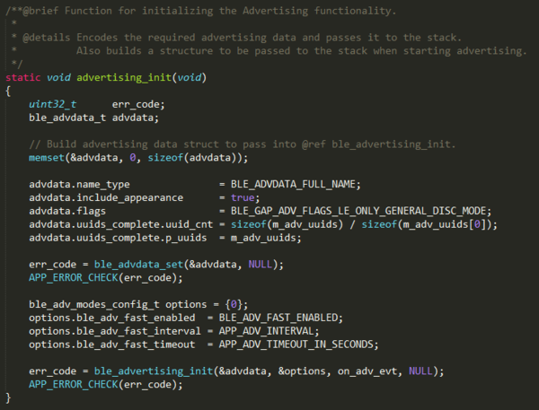
BLE Advertising Initialization
Here is an example code to initialize BLE advertising as a peripheral device.
Nordic UART Service Implementation
- Nordic controller is providing wireless UART service which t emulates a serial port over BLE. This is intended to serve as a peer to the phone application 'nRF UART' (available for iOS on Apple Store and for Android on Google Play Store) and also to demonstrate the usage of proprietary (vendor specific) service and characteristics with the S110 SoftDevice.
- The application includes one service namely the Nordic UART Service (UUID: 0x0001). The UUID of the Nordic UART Service is 6E400001-B5A3-F393-E0A9-E50E24DCCA9E.
- This service exposes two characteristics - one for receiving and and another for transmitting, as seen from the nRF51822 application..
- TX Characteristic (UUID: 6E400002-B5A3-F393-E0A9-E50E24DCCA9E): When the peer has enabled notification for the Tx Characteristic, the application can send data to the peer as notifications. The application will transmit all data received over UART as notifications.
- RX Characteristic (UUID: 6E400003-B5A3-F393-E0A9-E50E24DCCA9E): Peer can start sending data to the device by writing to the Rx Characteristic of the service. ATT Write Request or ATT Write Command can be used. The data received is sent on the UART interface.
Brief description of important code lines in Nordic BLE module
Adding proprietary service and characteristic
- The initialization of the proprietary service and its characteristics are done in ble_nus.c.
- The Nordic UART Service is added to the S110 SoftDevice as follows.
   // Add custom base UUID.
   err_code = sd_ble_uuid_vs_add(&nus_base_uuid, &p_nus->uuid_type);
   if (err_code != NRF_SUCCESS)
   {
       return err_code;
   }
   ble_uuid.type = p_nus->uuid_type;
   ble_uuid.uuid = BLE_UUID_NUS_SERVICE;
   // Add service.
   err_code = sd_ble_gatts_service_add(BLE_GATTS_SRVC_TYPE_PRIMARY,
                                       &ble_uuid,
                                       &p_nus->service_handle);
- The RX characteristic is added to the SoftDevice as follows. Notice that the read and write permissions of the characteristic and its CCCD are set as 'open' - which means there are no security restrictions on this characteristic. Also note that the type of the UUID (ble_uuid.type) is the value that was returned in the call to sd_ble_uuid_vs_add(). The TX characteristic is also added in a similar way.
   ble_gatts_char_md_t char_md;
   ble_gatts_attr_md_t cccd_md;
   ble_gatts_attr_t    attr_char_value;
   ble_uuid_t          ble_uuid;
   ble_gatts_attr_md_t attr_md;

   memset(&cccd_md, 0, sizeof(cccd_md));
   BLE_GAP_CONN_SEC_MODE_SET_OPEN(&cccd_md.read_perm);
   BLE_GAP_CONN_SEC_MODE_SET_OPEN(&cccd_md.write_perm);
   cccd_md.vloc = BLE_GATTS_VLOC_STACK;

   memset(&char_md, 0, sizeof(char_md));

   char_md.char_props.notify = 1;
   char_md.p_char_user_desc  = NULL;
   char_md.p_char_pf         = NULL;
   char_md.p_user_desc_md    = NULL;
   char_md.p_cccd_md         = &cccd_md;
   char_md.p_sccd_md         = NULL;

   ble_uuid.type             = p_nus->uuid_type;
   ble_uuid.uuid             = BLE_UUID_NUS_RX_CHARACTERISTIC;

   memset(&attr_md, 0, sizeof(attr_md));
   BLE_GAP_CONN_SEC_MODE_SET_OPEN(&attr_md.read_perm);
   BLE_GAP_CONN_SEC_MODE_SET_OPEN(&attr_md.write_perm);

   attr_md.vloc              = BLE_GATTS_VLOC_STACK;
   attr_md.rd_auth           = 0;
   attr_md.wr_auth           = 0;
   attr_md.vlen              = 1;

   memset(&attr_char_value, 0, sizeof(attr_char_value));
   attr_char_value.p_uuid    = &ble_uuid;
   attr_char_value.p_attr_md = &attr_md;
   attr_char_value.init_len  = sizeof(uint8_t);
   attr_char_value.init_offs = 0;
   attr_char_value.max_len   = BLE_NUS_MAX_RX_CHAR_LEN;

   return sd_ble_gatts_characteristic_add(p_nus->service_handle,
                                          &char_md,
                                          &attr_char_value,
                                          &p_nus->rx_handles);
Software UART Configuration
| Description | Interface | Bluefruit Port | SJOne Board Port |
|---|---|---|---|
| Supply Voltage | N/A | Vcc | 3.3 V |
| Ground | N/A | GND | GND |
| Bluefruit Module | UART3 |
P0.10 -> Rx P0.9 -> Tx |
Channel 1 -> TxD3 Channel 2 -> RxD3 |
| MODE | Data/Command mode selection | MOD | P2.0 |
| DFU select | Device Firmware Update | DFU | P2.1 |
UART initialization
- All application initialization and handling of data sent and received through BLE and UART are done in main.c.
- The UART initialization is done as shown in the code below. This code segment uses the UART driver provided in the SDK to perform the UART configuration. Note that the last parameter to the simple_uart_config function indicates that the application intends to use Hardware Flow Control. This means the RTS_PIN_NUMBER and CTS_PIN_NUMBER can be used as Ready-to-Send and Clear-to-Send pins respectively if you want Hardware flow control enabled. Here to communicate with SJOne board we have disabled HW flow control. The code below then enables the UART interrupt.
   simple_uart_config(RTS_PIN_NUMBER, TX_PIN_NUMBER, CTS_PIN_NUMBER, RX_PIN_NUMBER, HWFC);

   NRF_UART0->INTENSET = UART_INTENSET_RXDRDY_Enabled << UART_INTENSET_RXDRDY_Pos;

   NVIC_SetPriority(UART0_IRQn, APP_IRQ_PRIORITY_LOW);
   NVIC_EnableIRQ(UART0_IRQn);
Handling of data received over BLE
- When initializing the service in services_init() function, the application passes nus_data_handler to be used for handling the received data. When the Nordic UART Service indicates that there has been some data received over BLE from the peer, the same data is relayed to the UART. This function consists of the following piece of code.
   void nus_data_handler(ble_nus_t * p_nus, uint8_t * p_data, uint16_t length)
   {
       for (int i = 0; i < length; i++)
       {
           simple_uart_put(p_data[i]);
       }
       simple_uart_put('\n');
   }
Handling of data received over UART
- The data received from the UART though undergoes certain checks before getting relayed to the BLE peer using the Nordic UART Service. The following code is inside the UART Interrupt handler which will be called each time a character is received over the UART. Each of these characters is buffered up into a string until a 'new line' character is received OR the size of the string exceeds the limit indicated by NUS_MAX_DATA_LENGTH. Once one of these two conditions is met, the string is sent over BLE using ble_nus_send_string function.
- By default, the macro NUS_MAX_DATA_LENGTH is set to its maximum possible value, which is the maximum size of a notification packet, i.e BLE_ATT_MTU - 3, and should not be increased further.
   data_array[index] = simple_uart_get();
   index++;
   if ((data_array[index - 1] == '\n') || (index >= (BLE_NUS_MAX_DATA_LEN - 1)))
   {
       err_code = ble_nus_send_string(&m_nus, data_array, index + 1);
       if (err_code != NRF_ERROR_INVALID_STATE)
       {
           APP_ERROR_CHECK(err_code);
       }

       index = 0;
   }
Keil Projects Configuration for the SEGGER Debugger
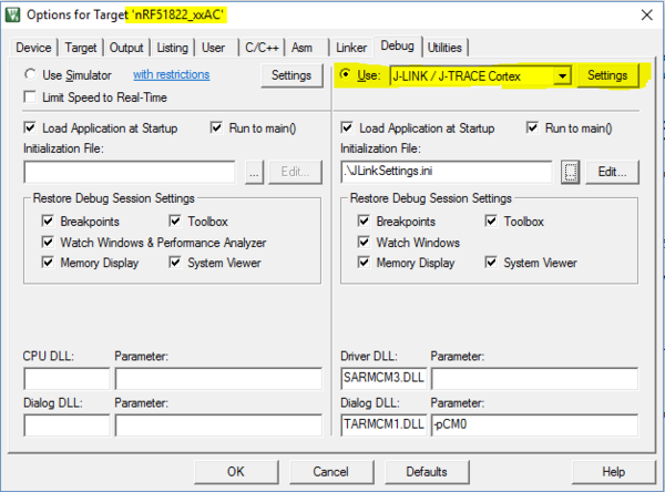
1. Double click on the uvision project file to open the Keil uVision IDE.
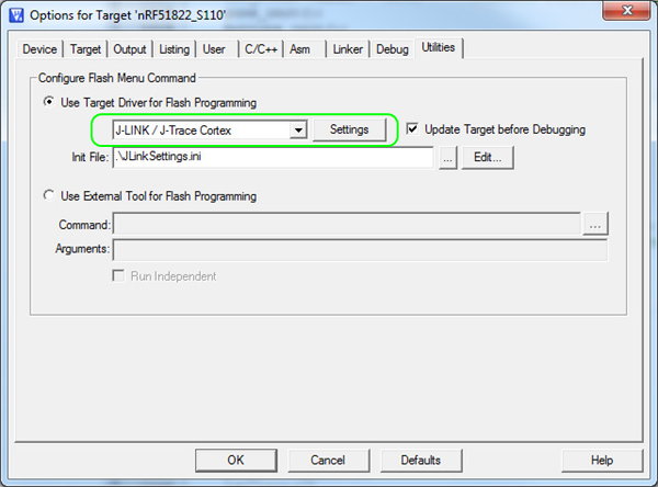
2. Click "Target Options" on the toolbar or click "Project" menu and select "Options for Target".
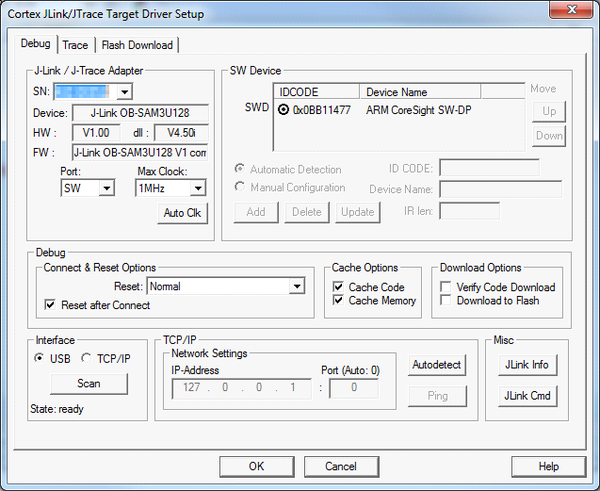
3. Under the Debug tab in the Use list, select J-LINK / J-Trace Cortex option as shown in Figure below.
4. Click Settings as shown in Figure 36. Both the SEGGER Control Panel and the Keil Target Driver Setup will open.
5. Click the Debug tab. Set Port to SW and Max Clock to 1 MHz. Make sure that SN and IDCODE are populated as seen in Figure below and click OK.
6. Select the J-Link device for target programming and provide the appropriate code memory algorithm.
7. If the J-Link serial number appears in the SN field, the device is properly installed. The default settings can be accepted by clicking OK, closing both the SEGGER Control Panel and Keil target Driver Setup.
Programming Bluefruit module using nRFgo Studio
- The Nordic nRFgo Studio is a Windows® application that enables engineers to quickly explore and evaluate radio performance and functionality. The application supports a range of radio testing, including output power and sensitivity. Engineers can also easily configure and set-up the tests to match their own specific application requirements.
- nRFgo Studio is designed to be used in conjunction with the Nordic nRFgo Starter Kit and Nordic nRFgo-compatible development kits. It supports auto detection of Nordic nRFgo motherboard and radio modules. It also support the nRF51 evaluation kits and programming nRF51 devices through SEGGER J-Link®
- nRFgo studio provides a visual editor for creating GATT clients (Profiles) and GATT Services for the nRF8001 and generating the nRF8001 Setup as a header file. The nRFgo studio is used to visually configure the nRF8002 and generate the configuration for the nRF8002. The nRFgo Studio features for nRF8001 and nRF8002 are standalone and do not require the Nordic nRFgo Starter kit.
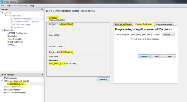
- Here is a screen capture of this software to program Nordic board.
- As you can see in Device Manager(bottom left) section board will be detected as a 'Segger <number>' via nRF51DK debug connector.
- In center section, you can see two regions. 1) Application firmware 2) SoftDevice firmware.
- Application firmware is the user provided application(.hex) file, means whatever application you want to run in Nordic controller, you have to load that firmware file in application region only.
- SoftDevice firmware is provided by Nordic which is used for BLE software stack library.
Generating custom BLE services using Bluetooth Developer Studio(BDS)
- Nordic provides BDS plugin for nRF51822/52xx controllers, so you can generate custom UUID based BLE services in BDS and it will generate code for BLE service initialization.
Benefit of having an external 32kHz crystal
- An external 32 kHz crystal will give lower average current consumption than using the RC oscillator, at the expense of cost and board space. There are primarily 3 reasons the current consumption is lower:
- The RC oscillator must be calibrated every 4 seconds to be accurate enough. Calibration normally takes about 17 ms, and requires the 16 MHz to be running, giving an average current consumption increase of about 6-7 µA.
- The receive window must be widened to account for the worse accuracy. Since the RC is 250 ppm, compared with typically 20-30 ppm for an external crystal, the radio must receive for a slightly longer time, giving an increase of average 1-2 µA.
- The run current or the RC is 0.8 µA instead of 0.4 µA for a typical crystal.
In total, this gives 8-10 µA extra average current consumption. Depending on application, this may be enough to justify the cost and board space for a crystal.
Building Android Application
Testing & Technical Challenges
Describe the challenges of your project. What advise would you give yourself or someone else if your project can be started from scratch again? Make a smooth transition to testing section and described what it took to test your project.
Include sub-sections that list out a problem and solution, such as:
UART Communication Challenge
- Problem - Tried to communicate between SJOne and Bluefruit module over UART interface with built-in firmware, but not able to receive data correctly as HW flow control was enabled in Nordic firmware.
- Solution - Flashed new firmware in Bluefruit module with turning off HW flow control for UART interface.
nRF51822 Firmware Update Challenge
- Problem - Updated inbuilt firmware which comes with Bluefruit module using Device Firmware Update service to turn off hardware flow control in UART interface, it updates successfully but then that firmware was not working as expected because of crystal settings which are being used for Bluetooth Softdevice drivers.
- Solution - DFU service was not available to use as we have updated firmware with wrong settings so need to upload now new firmware using Serial Wire Debug(SWD) Programmer. Then we have updated new firmware with crystal settings "NRF_CLOCK_LFCLKSRC_RC_250_PPM_250MS_CALIBRATION" (On chip Low Frquency Crystal) using nRFGoStudio Software. Then each time we have used SWD programmer to flash any new version of firmware.
Receiving data at higher data rate
- Problem - We were receiving sensor data at very low speed(80 bytes in 500 ms) and we wanted sensor data in real time(80 bytes in 20ms) to be plotted on the graph.
- Solution - In normal BLE peripheral device, to decrease power usage, the connection interval would be in between 500ms-4000ms. Because of this connection interval we were getting sensor data at lower rate. So we have decreased connection interval to 20ms in order to get sensor data at its maximum throughput level.
Conclusion
Conclude your project here. You can recap your testing and problems. You should address the "so what" part here to indicate what you ultimately learnt from this project. How has this project increased your knowledge?
Project Video
Upload a video of your project and post the link here.
Project Source Code
References
Acknowledgement
Any acknowledgement that you may wish to provide can be included here.
References Used
List any references used in project.
- Adafruit Bluefruit LE UART Friend module datasheet
- nRF51822 Documentation
- nRF51_SDK_v10 - Software Development Kit for Nordic BLE development
- Nordic Development Tutorials and forum
- Nordic Training Videos
- Segger J Link Debugger tool
- Bluefruit LE Sniffer
- Python api for BLE sniffer
- DFU Updates
- Sample firmware images for Bluefruit module
- Bluefruit Arduino example codes
Appendix
You can list the references you used.
Scratch pad
1. Collect sensor data from all the sensors
a. IMU
b. Temp
c. Light
Collect values and transmit over individual BLE service nrf51822 -> no OS.
Put OS on top of that and replace NORDIC BLE UART , with own ble service and use specific UUID
Profiles ->
Light Sensor (Notify/Indicate/Raw read)
Reading for BLE overview -
http://mbientlab.com/blog/bluetooth-low-energy-introduction/
BLE Part
https://www.adafruit.com/product/2479
Try and implement FreeRTOS / RTX on the AdaFruit BLE nordic Part
Surojit - Start with the Android side of things [04/23/2016]
==> Balance a ball based on mobile app based on IMU reading from board.
==> Real time graph for each of the Sensor Readings.
==> Push data on to cloud
- Dhruv- 1 sensor and BLE nordic and tune it , Make BLE profile (Temperature) [04/23/2016]
- Dhruv- 1 more sensor and BLE nordic , Make BLE profile (Light) [04/23/2016]
- Surojit - 1 more sensor and BLE nordic , Make BLE profile (IMU) [04/17/2016]
- Dhruv - FreeRTOS [04/23/2016]
Extra Credit
Over the Air Update (OTA)
