S16: Laser Cutter Motor Controller
Contents
Grading Criteria
- How well is Software & Hardware Design described?
- How well can this report be used to reproduce this project?
- Code Quality
- Overall Report Quality:
- Software Block Diagrams
- Hardware Block Diagrams
- Schematic Quality
- Quality of technical challenges and solutions adopted.
Project Title
Laser Cutter Motor Controller
Abstract
This is a PoC (Proof of Concept) project to aid in the design of my CmpE 195A senior project. For this PoC I will be using a joystick hooked up to one SJOne board to wirelessly (or not) control another SJOne board which will in turn control 2 stepper motor controller chips to finally control 2 stepper motors on my laser cutter.
Objectives & Introduction
Show list of your objectives. This section includes the high level details of your project. You can write about the various sensors or peripherals you used to get your project completed.
Team Members & Responsibilities
- Alex Kennedy
- Hardware design
- Software design
- System integration
Schedule
| Week# | Date | Task | Actual |
|---|---|---|---|
| 1 | 4/11 | Initialization | Completed |
| 2 | 4/18 | PCB Design | Completed. Some of the traces are not ideally placed but they should still work. |
| 3 | 4/25 | Order Parts and Start Coding | Completed |
| 4 | 5/2 | Finish Coding and Assemble | Not completed. Due to problems with assembling the board, it is going to be impossible to complete this project on time. (See the Issues section for details.) |
| 5 | 5/9 | Finalization | Completed. |
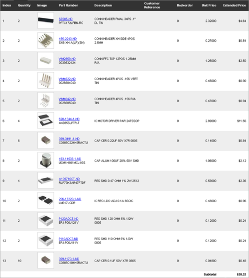
Parts List & Cost
Design & Implementation
The design section can go over your hardware and software design. Organize this section using sub-sections that go over your design and implementation.
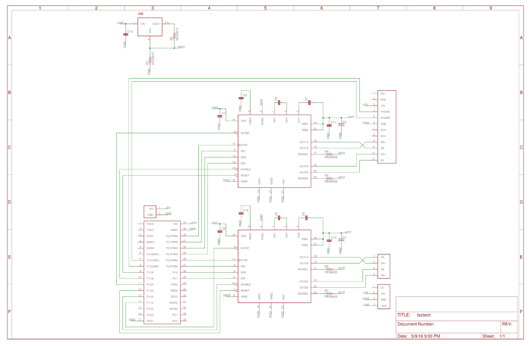
Hardware Design
Hardware Interface
In this section, you can describe how your hardware communicates, such as which BUSes used. You can discuss your driver implementation here, such that the Software Design section is isolated to talk about high level workings rather than inner working of your project.
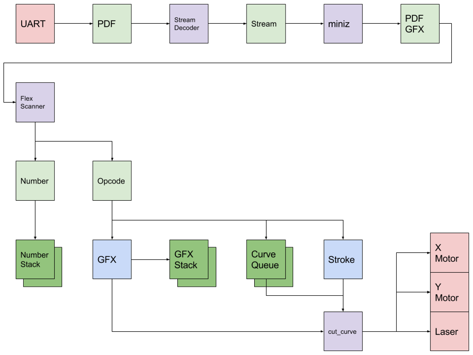
Software Design
Implementation
This section includes implementation, but again, not the details, just the high level. For example, you can list the steps it takes to communicate over a sensor, or the steps needed to write a page of memory onto SPI Flash. You can include sub-sections for each of your component implementation.
Testing & Technical Challenges
Describe the challenges of your project. What advise would you give yourself or someone else if your project can be started from scratch again? Make a smooth transition to testing section and described what it took to test your project.
Include sub-sections that list out a problem and solution, such as:
Issue #1) Assembly
This project was ultimately stopped by a lack of manufacturing hardware. The Allegro stepper motor driver chips use a eTSSOP-24 SMD pad layout. This means that the pin pitch (spacing between pins) is only 0.6 mm. This proved too hard to solder by hand. In order to resolve this issue, a solder paste mask is required. This would allow solder paste to be applied to the pads only and would limit the amount of pin bridging. Due to time constraints it is impossible to order one of these in time for demo.
Conclusion
Conclude your project here. You can recap your testing and problems. You should address the "so what" part here to indicate what you ultimately learnt from this project. How has this project increased your knowledge?
Project Video
Upload a video of your project and post the link here.
Project Source Code
References
Acknowledgement
Any acknowledgement that you may wish to provide can be included here.
References Used
List any references used in project.
Appendix
You can list the references you used.


