S16: Laser Cutter Motor Controller
Contents
Project Title
Laser Cutter Motor Controller
Abstract
This is a PoC (Proof of Concept) project to aid in the design of my CmpE 195A senior project. For this PoC I will be using a joystick hooked up to one SJOne board to wirelessly (or not) control another SJOne board which will in turn control 2 stepper motor controller chips to finally control 2 stepper motors on my laser cutter.
Objectives & Introduction
The LazTech Motor Driver should be able to drive two motors independently. It should be able to follow both scripted and manually input movement commands which include: moves, lines, and curves.
Team Members & Responsibilities
- Alex Kennedy
- Hardware design
- Software design
- System integration
Schedule
| Week# | Date | Task | Actual |
|---|---|---|---|
| 1 | 4/11 | Initialization | Completed |
| 2 | 4/18 | PCB Design | Completed. Some of the traces are not ideally placed but they should still work. |
| 3 | 4/25 | Order Parts and Start Coding | Completed |
| 4 | 5/2 | Finish Coding and Assemble | Not completed. Due to problems with assembling the board, it is going to be impossible to complete this project on time. (See the Issues section for details.) |
| 5 | 5/9 | Finalization | Completed. |
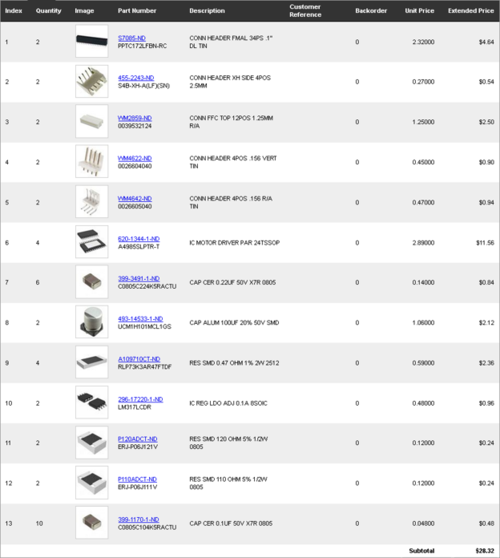
Parts List & Cost
Design & Implementation
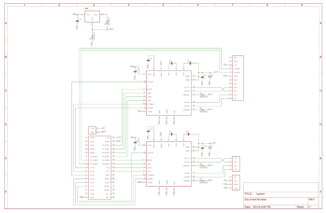
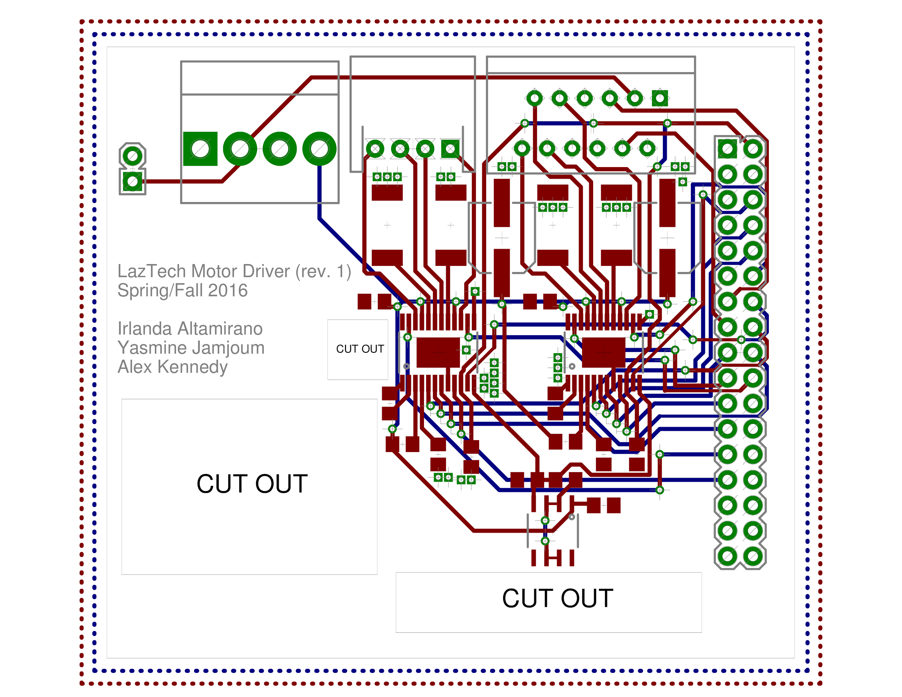
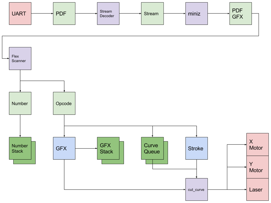
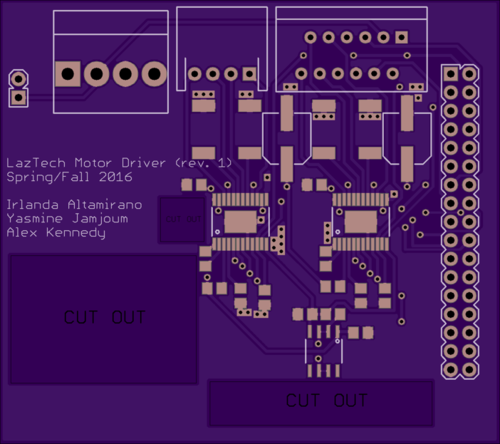
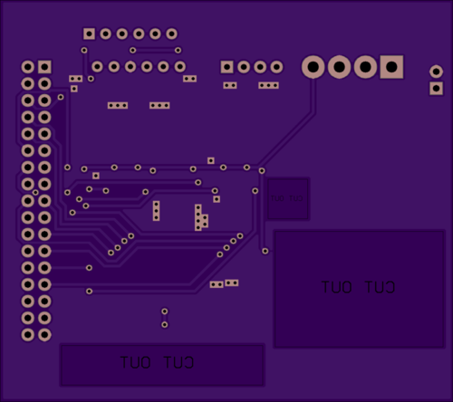
Below are the hardware and software design files. This includes both the hardware schematics and board layout (all layers). In addition the software workflow is provided.
The main interface is a simple GPIO clock pulse interface that latches into the Allegro stepper motor driver chips. Various options can be specified such as the direction, step size, and sleep functions. Details of how the interface works can be found in the Allegro documentation.
Hardware Design
Hardware Interface
In this section, you can describe how your hardware communicates, such as which BUSes used. You can discuss your driver implementation here, such that the Software Design section is isolated to talk about high level workings rather than inner working of your project.
Software Design
For this project the task will enter the workflow at the flex scanner stage. from here we can manually generate move, line, and curve primitives which can be queued into the curve queue. For this project only one static graphics stack will be required and therefore graphics opcodes will not need to be decoded. Additionally a graphics stack will not be required. Once a set of curves is queued and a stroke command is sent, the cut_curve task will be started which will then perform the actual motor control movements.
Implementation
The following are simulated renders of the above board and schematic.
Testing & Technical Challenges
Given another few weeks on this project, it could have been completed. A large portion of the learning from this project was in the hardware assembly phase. I learned that to effectively design and implement custom PCBs with SMT a good rework station or oven is required. I will be purchasing these items in the very near future.
Issue #1 Assembly
This project was ultimately stopped by a lack of manufacturing hardware. The Allegro stepper motor driver chips use a eTSSOP-24 SMD pad layout. This means that the pin pitch (spacing between pins) is only 0.6 mm. This proved too hard to solder by hand. In order to resolve this issue, a solder paste mask is required. This would allow solder paste to be applied to the pads only and would limit the amount of pin bridging. Due to time constraints it is impossible to order one of these in time for demo.
Conclusion
This project has ultimately given me more experience with full system engineering. I feel like I have a complete mastery over the software side of this class so it was really interesting to try my hand and more PCB design and system integration. Although a failure in this class, the lessons learned here will help me in CmpE 195B and in future endeavors.
Project Source Code
References
Acknowledgement
I would like to thank my CmpE 195A group for their help in this project.
References Used
List any references used in project.
Appendix
You can list the references you used.
