Difference between revisions of "F22: Embedded Gamers"
(→Implementation) |
(→Schedule) |
||
| Line 159: | Line 159: | ||
* Develop enemy spaceships game algorithm | * Develop enemy spaceships game algorithm | ||
* Control dynamic movement of player spaceship. | * Control dynamic movement of player spaceship. | ||
| + | * Create MP3 Driver | ||
| | | | ||
* <span style="color:red">Not started</span> | * <span style="color:red">Not started</span> | ||
* <span style="color:red">Not started</span> | * <span style="color:red">Not started</span> | ||
* <span style="color:red">Not started</span> | * <span style="color:red">Not started</span> | ||
| + | * <span style="color:green">Completed</span> | ||
|- | |- | ||
! scope="row"| 7 | ! scope="row"| 7 | ||
Revision as of 06:54, 15 November 2022
Contents
Grading Criteria
- How well is Software & Hardware Design described?
- How well can this report be used to reproduce this project?
- Code Quality
- Overall Report Quality:
- Software Block Diagrams
- Hardware Block Diagrams
- Schematic Quality
- Quality of technical challenges and solutions adopted.
Project Title
Guardians of the Galaxy
Abstract
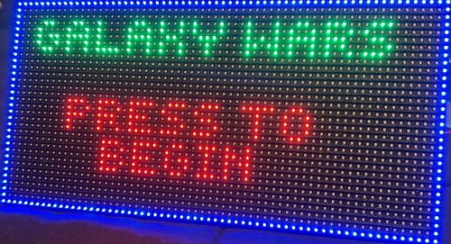
A horizontal type of space invader game. Players can control the spaceship on the screen composed of an LED matrix in a rectangular shape. The spaceship can shoot horizontally from left to right in order to destroy its enemies. The entire map will flow in the opposite direction of where the spaceship is flying. The speed of the map flow and the number of enemies will increase at higher difficulty levels. The spaceship takes damage from colliding with enemies themselves or their bullets. The game will end when the health of the controlled spaceship is depleted.
Objectives & Introduction
Technical Responsibilities
| Administrative Roles | ||||
|---|---|---|---|---|
|
Bruce Jiang | |||
|
Bruce Jiang | |||
|
Ritu Patil | |||
|
Bruce Jiang | |||
|
Bruce Jiang & Ritu Patil | |||
|
Bruce Jiang & Phil Bloxom | |||
Administrative Responsibilities
| Administrative Roles | ||||
|---|---|---|---|---|
|
Ritu Patil | |||
|
Bruce Jiang | |||
|
Phil Bloxom | |||
|
Bruce Jiang | |||
|
Ritu Patil | |||
Schedule
| Week# | Start Date | End Date | Task | Status |
|---|---|---|---|---|
| 1 |
|
|
|
|
| 2 |
|
|
|
|
| 3 |
|
|
|
|
| 4 |
|
|
|
|
| 5 |
|
|
|
|
| 6 |
|
|
|
|
| 7 |
|
|
|
|
| 8 |
|
|
|
|
| 9 |
|
|
|
|
| 10 |
|
|
|
|
Bill of Materials (General Parts)
| Part Name | Part Model & Source | Quantity | Cost Per Unit (USD) |
|---|---|---|---|
|
|
|
|
|
|
| |
|
|
| |
|
|
| |
|
|
| |
|
|
|
Overall Design
Hardware Design
Discuss your hardware design here. Show detailed schematics, and the interface here.
Hardware Interface
In this section, you can describe how your hardware communicates, such as which BUSes used. You can discuss your driver implementation here, such that the Software Design section is isolated to talk about high level workings rather than inner working of your project.
Software Design
Show your software design. For example, if you are designing an MP3 Player, show the tasks that you are using, and what they are doing at a high level. Do not show the details of the code. For example, do not show exact code, but you may show psuedocode and fragments of code. Keep in mind that you are showing DESIGN of your software, not the inner workings of it.
Implementation
This section includes implementation, but again, not the details, just the high level. For example, you can list the steps it takes to communicate over a sensor, or the steps needed to write a page of memory onto SPI Flash. You can include sub-sections for each of your component implementation.
RGB LED Matrix
Hardware Design
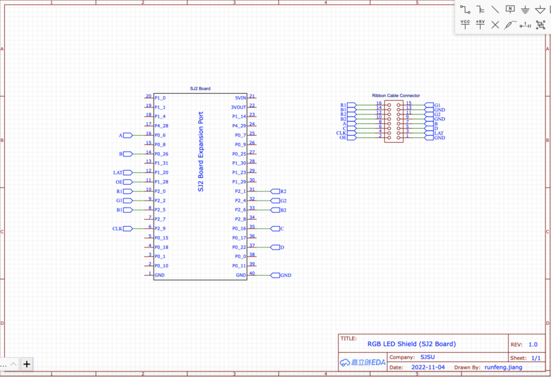
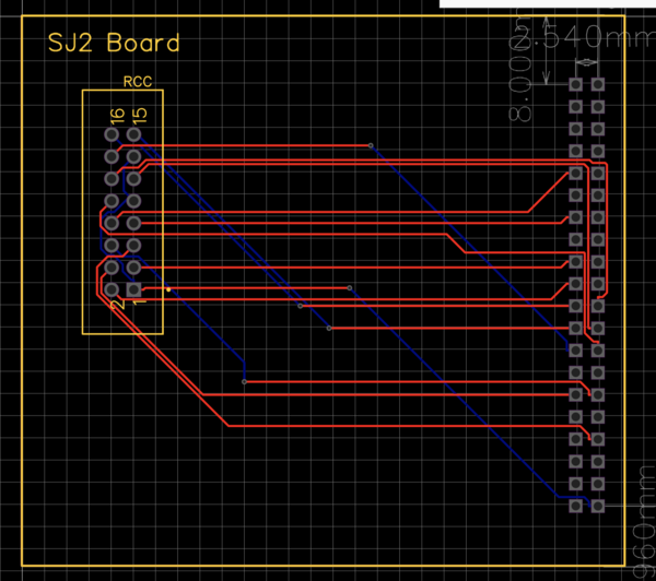
Below are symbol and footprint for custom component-part in EasyEDA tool. These parts would be used in future PCB design.
Hardware Interface
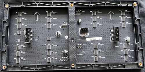
The 32x64 LED matrix is from Adafruit, with user mannual. It is composed of two upper and lower sectional LED pannels. Each pannel has R, G, B led channels and A, B, C, and D row control registers. Addtionally, column shift is controlled by Latch bit, clock is controled by CLK, and OE turns LED off when switching rows.
|
Connectivity Table LED Matrix to Sj2 Board:
|
Software Design
LED matrix io and driver is developed for communication between boards and LED matrix. IO driver consists of pin inialization by using gpio.h for each rgb channels, row selection register, CLK, LAT, and OE pins. By using "led_matrix_io.h" developers can using public function led_matrix_io_init and other basic controller functions.
For LED matrix driver, it is based on the previous IO driver to provide LED screen update, clean, init, and draw functionalities.
Implementation
Rtos Tasks:
- Updating Display: for display to continuously updating screen, a task is assigned for running the display_update function from the driver every 500 milliseconds.
Testing & Technical Challenges
Describe the challenges of your project. What advise would you give yourself or someone else if your project can be started from scratch again? Make a smooth transition to testing section and described what it took to test your project.
Include sub-sections that list out a problem and solution, such as:
<Bug/issue name>
Discuss the issue and resolution.
Conclusion
Conclude your project here. You can recap your testing and problems. You should address the "so what" part here to indicate what you ultimately learnt from this project. How has this project increased your knowledge?
Project Video
Upload a video of your project and post the link here.
Project Source Code
References
Acknowledgement
Any acknowledgement that you may wish to provide can be included here.
References Used
List any references used in project.
Appendix
You can list the references you used.


