Difference between revisions of "S15: Rubik's Cube Solver"
Proj user15 (talk | contribs) (→Bluetooth Interface) |
Proj user15 (talk | contribs) (→Robot claw interface) |
||
| Line 175: | Line 175: | ||
=== Hardware Interface === | === Hardware Interface === | ||
| − | |||
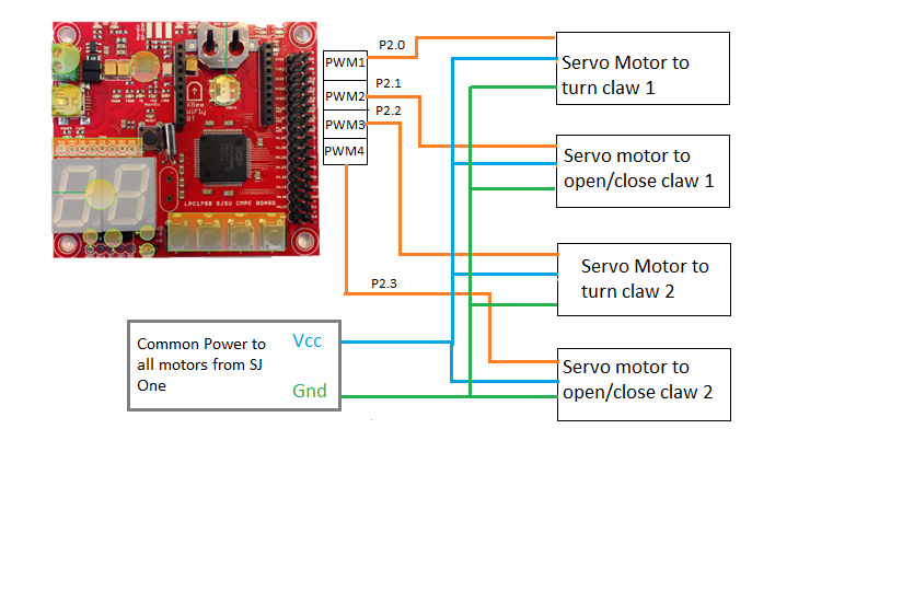
The hardware implementation includes the the interfacing the robot claws to SJ One board. The following block diagram represents the connection of the motors to the board. | The hardware implementation includes the the interfacing the robot claws to SJ One board. The following block diagram represents the connection of the motors to the board. | ||
[[File:S15 Rubik'sCubeSolver Motorblock.png|Right|Motor Connection with SJ One]] | [[File:S15 Rubik'sCubeSolver Motorblock.png|Right|Motor Connection with SJ One]] | ||
| Line 214: | Line 213: | ||
|} | |} | ||
<br> | <br> | ||
| + | ==== Robot claw interface ==== | ||
| − | [[File:CPME244_S15_RubikCubeSolver_motor.jpg| | + | [[File:CPME244_S15_RubikCubeSolver_motor.jpg|200px|left|Servo Motor]] |
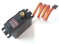
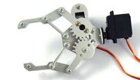
'''''Motor''''' :The motors used to achieve the movement are MG995 Servo motor. Servo motors are preferred due to the precise movements of the arms by 90 degree, which was required. The rotation was controlled by the PWM value passed to the particular motor. The open and close function of the claw was controlled by one motor(holder motor). The clockwise and anticlockwise rotation of the claw was controlled by the other motor(turner motor). The figure depicts the claw attached to the motor (turner motor).<br> | '''''Motor''''' :The motors used to achieve the movement are MG995 Servo motor. Servo motors are preferred due to the precise movements of the arms by 90 degree, which was required. The rotation was controlled by the PWM value passed to the particular motor. The open and close function of the claw was controlled by one motor(holder motor). The clockwise and anticlockwise rotation of the claw was controlled by the other motor(turner motor). The figure depicts the claw attached to the motor (turner motor).<br> | ||
| − | [[File:CPME244 S15 RubikCubeSolver claw.jpg| | + | [[File:CPME244 S15 RubikCubeSolver claw.jpg|200px|right|Robot claw]] |
'''''Robot Claw''''' : We choose to use the Dangu Claw because of the design and features. It was designed to in corporate both the motors on. One for opening and closing operation and the other for turning the claw. The features of the claw are as follows, <br> | '''''Robot Claw''''' : We choose to use the Dangu Claw because of the design and features. It was designed to in corporate both the motors on. One for opening and closing operation and the other for turning the claw. The features of the claw are as follows, <br> | ||
* The Dagu Aluminum Gripper (with Servos) is made from 3mm thick aluminium | * The Dagu Aluminum Gripper (with Servos) is made from 3mm thick aluminium | ||
Revision as of 07:15, 25 May 2015
Contents
Rubik's Cube Solver
Abstract
The Rubik’s Cube is a common 3-D combination puzzle known and loved by people of all ages. The mathematics of Rubik’s Cubes has been explored in great detail ever since the beginning of their production in the 1980’s.The aim of the project is to develop Rubik’s cube solving algorithm to solve the Rubik’s cube in shortest possible time without any human intervention. The project explored areas of - research and development, testing and debugging, and documentation.
Objectives & Introduction
The goal of the project is to write the software and create the hardware required to autonomously solve the Rubik’s cube. The first part of this project consisted of research on the mathematics of the Rubik’s Cube and how that is used for various solutions to the cube. Next, the focus was put on making a Windows based GUI through which the user can input the arrangement of colors for all the faces on the cube. Finally, the commands to move the robotic arms are send via the sjone board to the servos.
Team Members & Responsibilities
- Nikhil Chaturvedi
- Cube solving algorithm
- Interface SJOne with cube solving claws
- Connectivity from console to SJOne board
- Preeti Benake
- Build the cube solving claws
- Interface cube algorithm with claws
- Rajashree Kambli
- Connectivity from Console to SJOne board
- Updating the wiki page
- Shahid Qureshi
- Build the cube solving arms
Team Schedule
| Sl.No | Start Date | End Date | Task | Status | Actual Completion Date |
|---|---|---|---|---|---|
| 1 | 02/28/2015 | 03/02/2015 | Finalized high level design architecture | Completed on time | 03/02/2015 |
| 2 | 02/28/2015 | 04/17/2015 | Investigating Robotic arm design; eliminated few hardware options. | Completed on time | 04/17/2015 |
| 3 | 03/07/2015 | 03/09/2015 | Investigated interfacing console with SJOne board. | Completed on time | 03/09/2015 |
| 4 | 03/10/2015 | 03/14/2015 | Investigated BlueZ Bluetooth stack for Python and C.(Decided not to go ahead with this method) | Completed on time | 03/14/2015 |
| 5 | 03/29/2015 | 04/17/2015 | Implementing Bluetooth interfacing of SJOne board using C BlueZ and Console using PyblueZ (Decided not to go ahead with this method) | Completed on time | 04/17/2015 |
| 6 | 04/18/2015 | 04/20/2015 | Order and test the hardware components (Had delays getting parts from eBay) | Completed on time | 04/27/2015 |
| 7 | 04/22/2015 | 05/19/2015 | Interfacing the motors to SJOne board | Completed | 05/20/2015 |
| 8 | 04/10/2015 | 04/24/2015 | Investigating and implementation of Rubik cube solving algorithm (Kociemba's algorithm) | Completed | 04/27/2015 |
| 9 | 04/10/2015 | 05/08/2015 | with | Completed | 05/09/2015 |
| 9 | 04/28/2015 | 05/15/2015 | Build the Robot arm and test the controls | Completed | 05/21/2015 |
| 10 | 05/08/2015 | 05/20/2015 | Implement Bluetooth connectivity module | Completed | 05/20/2015 |
| 11 | 05/11/2015 | 05/22/2015 | Testing | Completed | 05/23/2015 |
Parts List & Cost
| Item# | Part Desciption | Vendor | Qty | Cost |
|---|---|---|---|---|
| 1 | Servo Motors | 6 | $56.58 | |
| 2 | Robotic Claw | 2 | $39.92 | |
| 3 | Speed Rubik cube | 2 | $21.48 | |
| 4 | Turnable table for Motors | 1 | $7.99 | |
| 5 | Robotic Claw stands | 2 | $7.52 | |
| 6 | Wires and other Accessories | --- | $16.5 |
Design & Implementation
The design section can go over your hardware and software design. Organize this section using sub-sections that go over your design and implementation.
Hardware Design
Discuss your hardware design here. Show detailed schematics, and the interface here.
Hardware Interface
The hardware implementation includes the the interfacing the robot claws to SJ One board. The following block diagram represents the connection of the motors to the board.

| Description | Motor Pin | SJOne Development Board Pins | Commands | Note | |
|---|---|---|---|---|---|
| Holder Servo Motor |
P2.0 and P2.2 PWM |
PWM motor(PWM::pwm1, 50); PWM motor(PWM::pwm3, 50); |
Sets PWM signal of 50 Hz Sets PWM signal of 50 Hz Opening and Closing the claw. | ||
| Tuner Servo Motor |
P2.1 and P2.3 PWM |
PWM servo(PWM::pwm2, 50); PWM servo(PWM::pwm4, 50); |
Sets PWM signal of 50 Hz Sets PWM signal of 50 Hz Turn the claw clockwise and anticlockwise. |
Robot claw interface
Motor :The motors used to achieve the movement are MG995 Servo motor. Servo motors are preferred due to the precise movements of the arms by 90 degree, which was required. The rotation was controlled by the PWM value passed to the particular motor. The open and close function of the claw was controlled by one motor(holder motor). The clockwise and anticlockwise rotation of the claw was controlled by the other motor(turner motor). The figure depicts the claw attached to the motor (turner motor).
Robot Claw : We choose to use the Dangu Claw because of the design and features. It was designed to in corporate both the motors on. One for opening and closing operation and the other for turning the claw. The features of the claw are as follows,
- The Dagu Aluminum Gripper (with Servos) is made from 3mm thick aluminium
- The gripper will open in excess of 50mm
- The servos provide 2.3Kg/cm of torque at 6V. and 1.8Kg/cm@3.3V
- It comes pre-assembled in a plastic bag
- Servo Features : Standard PWM Interface
Bluetooth Interface
Basic Bluetooth module (JY-MCU HC-06) was borrowed from Sreeharsha to use in the project. This particular series (HC-06) has four pins RX, TX, VCC and GND works in slave mode.
Note: Although VCC pin indicates that the module works with 3.6-6V, connecting it to the LPC1758 3.3V output worked fine.
This project uses UART3 for communication.The setting for UART is: Baud Rate - 115200, no parity, one start bit and one stop bit.
Software Design
Show your software design. For example, if you are designing an MP3 Player, show the tasks that you are using, and what they are doing at a high level. Do not show the details of the code. For example, do not show exact code, but you may show psuedocode and fragments of code. Keep in mind that you are showing DESIGN of your software, not the inner workings of it.
Implementation
Cube Solving Algorithm
The cube algorithm takes a scrambled cube and give a solution string. The steps involved in solving the cube is as follows,
1. Read the scrambled colors from the text file that the Python GUI
module wrote to.
2. Read these values into the main position holder array.
3. Hold a reference to the adjacent colors with respect to the top face.
4. Calculate the permutations for aligning the front, back, left and
right faces to the top face. Calculate the movements and the number of
rotations required to make these movements
5. Make changes to the main position holder after getting the
movements based on the permutations.
6. Calculate the permutations for solving the bottom layer which
consists of colors on bottom, left, right, front and back faces.
7. Calculate the the rotations for this solution.
8. Check if all the faces contain just one color. If yes, goto step 9,
else goto step 6.
9. Stop the algorithm.
Python GUI Module
We need a way to have the cube solving algorithm know the scrambled cube colors. While we could easily do this by manually changing these values for every run in the solver algorithm, this does not make for a good system design. The Python module presents a GUI for each face of the cube using which we select the colors of them based on a scrambled cube. After reading each face, we check if the total number for each color is the same. If yes, we write the faces of the cube to a file on the local machine.
Cube rotating arms
The robotic arms take the solution from the cube solving algorithm and convert them into the corresponding movements. We made use of two robotic claws, with two servo motors for each claw. This gives us four degrees of freedom to turn the cube. Here is how the arm functions,
The claws are mounted at 90 degrees to each other and the rotations
are as follows,
1. The right side is turned clockwise and counter clockwise.
2. The bottom side is turned clockwise and counter clockwise.
3. To turn the top face and left face, the whole cube is rotated and a
combination of the right claw and the left claw is used.
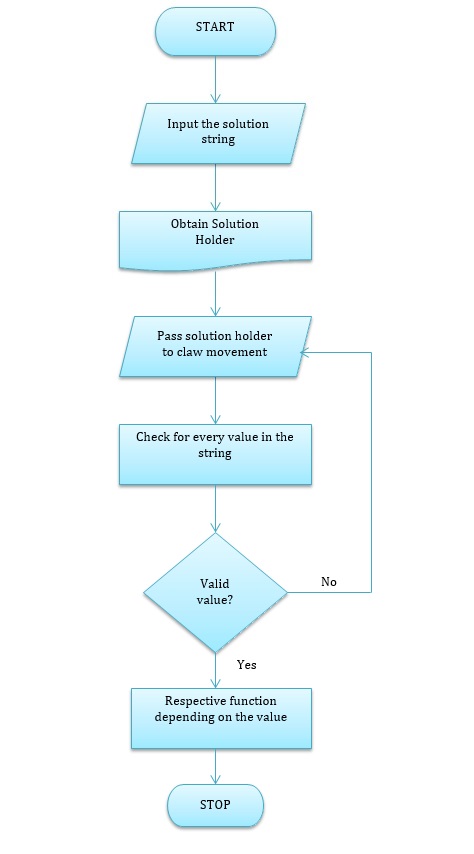
The cube rotating algorithm reads the solution file that the cube solving algorithm wrote to and converts the characters into a simpler notation for ease of programming.
Bluetooth module
This module sends the solution string from the solving algorithm to SJOne board. The sender is written in Java, which searches for Bluetooth devices in its vicinity and the service of each device. On SJOne board, we have a Bluetooth device which is set at 115200 Baud rate and listens for incoming connections and reads bytes of data sent from the Java console. We used Blue cove stack for our implementation.
Testing & Technical Challenges
1. The most challenging part of the project was to get the solution to
a scrambled cube. Initially we chose to solve a 3x3 cube but we chose
a 2x2 cube instead because solving a 3x3 cube took a lot of time and
with the limited time we had, we could not spend more time trying to
solve instead of actually getting to a solution.
2. The 2x2 cube solving algorithm used too much of memory allocation
for calculating a lot of combinations for aligning top face with the
adjacent sides. Due to this we could not run the algorithm on SJOne
board. Instead, we chose to run the algorithm on a PC and send the
solution string to the board to run the servo motor controller.
3. We have two robotic arms which can turn left/right and top/bottom.
Due to this, there we had to figure out a way to rotate the other
remaining faces using a combination of the turns of the two claws.
4. We had problems using the BlueCove Bluetooth stack in Java to
connect to SJOne board which had a Bluetooth device on board. We were
unable to get the push service from the device and resorted to using
BlueTerm application on Android for connecting with the code that is
running on SJOne board. We are still working to find a solution to
this, but since the other much important modules took up time, we
could not give enough time to this.
Conclusion
Conclude your project here. You can recap your testing and problems. You should address the "so what" part here to indicate what you ultimately learnt from this project. How has this project increased your knowledge?
Project Video
Upload a video of your project and post the link here.
Project Source Code
References
Acknowledgement
We would like to thank Preet, our instructor for the CMPE-244(Embedded software) class, for giving us all the useful and time saving inputs and also for being patient and tolerating us throughout the semester. Secondly, we would also like to thank our wonderful ISA's - Divya, Dhawal, Sreeharsha and Shashank, for guiding us and showing us the proper direction while working on the project.
References Used
http://www.nxp.com/documents/user_manual/UM10360.pdf
http://www.socialledge.com/sjsu/index.php?title=SJ_One_Board
http://www.electronicoscaldas.com/datasheet/MG995_Tower-Pro.pdf
https://www.thenewboston.com/videos.php?cat=99 (We used this website to learn about the basics of the Python GUI)
Appendix
You can list the references you used.


