Difference between revisions of "F13: BarkMaster2000"
Proj user10 (talk | contribs) |
Proj user10 (talk | contribs) |
||
| Line 121: | Line 121: | ||
| − | == | + | === Power === |
[[File:BM2000_5VRegBoardTop.JPG|200px|thumb|center|Figure XX]] | [[File:BM2000_5VRegBoardTop.JPG|200px|thumb|center|Figure XX]] | ||
| − | == | + | === MEMs Microphone Sensors === |
| − | == | + | === Mux and Signal Distribution Board === |
[[File:BM2000_MuxBoardTop.jpeg|200px|thumb|center|Figure XX]] | [[File:BM2000_MuxBoardTop.jpeg|200px|thumb|center|Figure XX]] | ||
[[File:BM2000_MuxBoardBottom.JPG|200px|thumb|center|Figure XX]] | [[File:BM2000_MuxBoardBottom.JPG|200px|thumb|center|Figure XX]] | ||
| − | == | + | === Passive Infrared Sensor === |
[[File:BM2000_PIR_SensorBoardTop.JPG|200px|thumb|center|Figure XX]] | [[File:BM2000_PIR_SensorBoardTop.JPG|200px|thumb|center|Figure XX]] | ||
[[File:BM2000_PIR_SensorBoardBottom.JPG|200px|thumb|center|Figure XX]] | [[File:BM2000_PIR_SensorBoardBottom.JPG|200px|thumb|center|Figure XX]] | ||
| − | == | + | === Motor Driver === |
Specifications: | Specifications: | ||
| − | + | * 4 x Low Resistance FET “H” Bridges | |
| − | + | * Each Channel Rated for 4A Stall Current | |
| − | + | * Easy-to-Use Control Logic | |
| − | + | * Current Monitoring for Each Channel. | |
| − | + | * Quadrature Encoder Mixing Circuitry | |
There are two power connectors on board. | There are two power connectors on board. | ||
One is for 5V logic and the other is the motor supply. | One is for 5V logic and the other is the motor supply. | ||
| Line 152: | Line 152: | ||
Width Modulated. | Width Modulated. | ||
Sensor Pin Names and Descriptions: | Sensor Pin Names and Descriptions: | ||
| − | + | * Ch1 PWM | |
| − | + | * Ch1 Direction | |
| − | + | * Ch2 PWM | |
| − | + | * Ch2 Direction | |
Product website: | Product website: | ||
| Line 162: | Line 162: | ||
| − | == | + | === Ultrasonic Distance Sensor Interface === |
Specifications: | Specifications: | ||
Power supply :5V DC | Power supply :5V DC | ||
| Line 193: | Line 193: | ||
Figure XX shows the bottom side of the Ultrasonic Sensor Board. Not the prettiest wire-wrap and soldering workmanship, but it got the job done. | Figure XX shows the bottom side of the Ultrasonic Sensor Board. Not the prettiest wire-wrap and soldering workmanship, but it got the job done. | ||
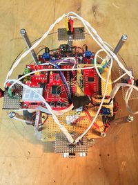
| − | == | + | === BarkMaster2000 Final Hardware Design Photos === |
[[File:BM2000_TopLevelTopView.JPG|200px|thumb|center|Figure XX]] | [[File:BM2000_TopLevelTopView.JPG|200px|thumb|center|Figure XX]] | ||
Revision as of 01:08, 24 November 2013
Contents
Project Title
Abstract
The Barkmaster2000(BM2000) is intended to sense sound, turn a motorized vehicle in response to that sound, and drive towards the sound unless it comes across an obstacle in its path. The idea is that Bryan’s dog likes to chase remote control cars, but hasn’t had a remote control car chase her yet. Here is a picture of Bryan’s dog.
Objectives & Introduction
- Triggered by sound
- Responds by turning to towards source of sound and moving for a predetermined amount of time
- Only turns in increments of 90 degrees
- Forward motion towards sounds stops when an object is detected or predetermined time expires
- Four independent MEMS sensors
- Combination of any sensor will trigger response
- Data is polled from each sensor and an aggregate is formed to increase chances of sensing in correct direction (aggregating the data is a means of filtering by integration)
- Each sensor must be directional – physical shield used to direct sound
Team Members & Responsibilities
- Bryan Canepa
- MEMs Sound Detection, Mux Interface, and Wireless On/Off control
- Patrick Ghorbanian
- Motor Controller, Ultrasonic Sensor Interface, and Power Distribution
Schedule
Show a simple table or figures that show your scheduled as planned before you started working on the project. Then in another table column, write down the actual schedule so that readers can see the planned vs. actual goals. The point of the schedule is for readers to assess how to pace themselves if they are doing a similar project.
| Week# | Date | Task |
|---|---|---|
| 1 | 10/8 | Develop Proposal |
| 2 | 10/15 | Purchase long lead parts |
| 3 | 10/22 | Interface MEMs and Ultrasonic Sensor Interfaces |
| 4 | 10/29 | Build up motor platform and test to verify that motor driver is sufficient to drive motors |
| 5 | 11/5 | Finalize MEMs detection and Motor Drive |
| 6 | 11/12 | Interface wireless On/Off and Finalize Ultrasonic Sensing |
| 7 | 11/19 | System Integration Phase 1 |
| 8 | 11/26 | System Integration Phase 2 |
| 9 | 12/3 | Demo Project and Finalized Wiki Page Submitted |
Parts List & Cost
| Part Number# (Supplier) | Description | Cost(EACH) | Quantity |
|---|---|---|---|
| BOB-09868(Sparkfun) | Breakout Board for ADMP401 MEMS Microphone | $9.95 | 4 |
| BOB-09056(Sparkfun) | Analog/Digital MUX Breakout | $4.95 | 1 |
| BOB-11978(Sparkfun) | Logic Level Converter(5V to 3.3V or 3.3V to 5V) | $1.95 | TBD |
| Rover 5 Motor Driver Board (Amazon) | Motor Driver (4WD) | $26.95 | 1 |
| HC-SR204 (Amazon) | SainSmart HC-SR04 Ultrasonic Distance Sensor | $4.88 | 1 |
| 2124277 (Amazon/Jameco) | 2WD Arduino Compatible Mobile Platform (contains 2 DC motors) | $70.44 | 1 |
| LPC1758 SJSU CMPE BOARD (SJSU) | Processor LPC1758 SJSU CMPE BOARD | $75 | 1 |
Design & Implementation
The design section can go over your hardware and software design. Organize this section using sub-sections that go over your design and implementation.
Hardware Design [Tools Used]
Power
MEMs Microphone Sensors
Mux and Signal Distribution Board
Passive Infrared Sensor
Motor Driver
Specifications:
  * 4 x Low Resistance FET “H” Bridges
  * Each Channel Rated for 4A Stall Current
  * Easy-to-Use Control Logic
  * Current Monitoring for Each Channel.
  * Quadrature Encoder Mixing Circuitry
  There are two power connectors on board.
  One is for 5V logic and the other is the motor supply.
  Be sure to turn on your logic supply before applying the power source for your motors.
  The board is rated for a maximum motor supply voltage of 12V.
  Control logic:
       The built in control logic allows each motor to be controlled by 2 pins. Driving the
       direction pin high or low will cause the motor to run forward or reverse. The PWM pin
       is used to control the motor speed. When this pin is low, the motor is off. When this pin
       is high the motor is at full power. To vary the speed of the motor this pin must be Pulse
       Width Modulated.
Sensor Pin Names and Descriptions:
   * Ch1 PWM
   * Ch1 Direction
   * Ch2 PWM
   * Ch2 Direction
Product website: https://www.sparkfun.com/products/11593 http://www.amazon.com/gp/product/B00AEOMUSM/ref=oh_details_o01_s00_i02?ie=UTF8&psc=1
Ultrasonic Distance Sensor Interface
Specifications:
   Power supply :5V DC
   Quiescent current : <2mA
   Effective angle: <15°
   Ranging distance : 2cm – 500 cm
   Resolution : 0.3 cm
Sensor Pin Names and Descriptions:
   Vcc = Positive Supply Voltage (5Vdc)
   Trig = Used to command the sensor to send out Ultrasonic signal
          (10usec TTL positive pulse required)
   Echo = The feedback signal that indicates when an object is detected
          (active high TTL pulse,  idle state low)
   Gnd = Ground
Note: Duration of echo high pulse is used to determine distance Distance = ((Duration of high level)*(Sonic :340m/s))/2 Based on our testing the echo response signal goes high within 456usec of trigger trigger signal going low
Product website: http://www.sainsmart.com/arduino-compatibles-1/sensor/ultrasonic-ranging-detector-mod-hc-sr04-distance-sensor.html
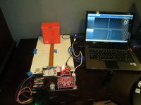
Figure XX shows the setup used to test out the Ultrasonic Distance Sensor Interface. Measurements were taken to verify that the sensor accuracy was sufficient. For our application accuracy on the order of +/-6.0 inches was sufficient since we are using the sensor to prevent the robot from running into our four legged friend. The sensor operation is fairly simple. A 10 usec positive going TTL pulse is sent to the Trigger Input. This commands the sensor to begin sampling the sensor and generate a pulse on the Echo pin that is also a positive going TTL pulse. The pulse width of the Echo pulse is a function of the distance of the detected object. The software driver will measure the pulse width on a GPIO input and calculate the distance using the distance equation stated above in the Sensor Pin Names and Descriptions section.
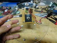
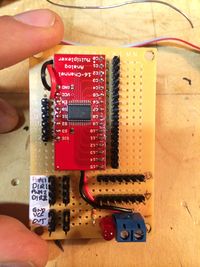
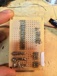
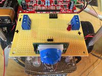
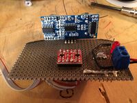
Figure XX shows the top side of the Ultrasonic Sensor Board. This sensor was difficult to mount as is, so it was installed on a perf board that mounts to the bottom side of the lower level section of the BM2000. Also installed on the perf board are supporting electronics and a ribbon cable that is routed to the top level of the BM2000. On the top level the ribbon cable connects to the BM2000 Mux Board. None of the ultrasonic sensor signals are multiplexed. This board was used as a signal distribution point since it is in close proximity to the SJSU LPC1758 Development Board. Since the ultrasonic sensor requires 5V(TTL) logic signals, a logic level converter was used to interface the Trigger and Echo signals with our SJSU LPC1758 Development Board.
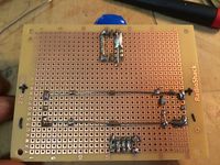
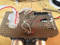
Figure XX shows the bottom side of the Ultrasonic Sensor Board. Not the prettiest wire-wrap and soldering workmanship, but it got the job done.
BarkMaster2000 Final Hardware Design Photos
Software Design
Show your software design. For example, if you are designing an MP3 Player, show the tasks that you are using, and what they are doing at a high level. Do not show the details of the code. For example, do not show exact code, but you may show psuedocode and fragments of code. Keep in mind that you are showing DESIGN of your software, not the inner workings of it.
Implementation
This section includes implementation, but again, not the details, just the high level. For example, you can list the steps it takes to communicate over a sensor, or the steps needed to write a page of memory onto SPI Flash. You can include sub-sections for each of your component implementation.
Testing & Technical Challenges
Describe the challenges of your project. What advise would you give yourself or someone else if your project can be started from scratch again? Make a smooth transition to testing section and described what it took to test your project.
Include sub-sections that list out a problem and solution, such as:
My Issue #1
Discuss the issue and resolution.
Conclusion
Conclude your project here. You can recap your testing and problems. You should address the "so what" part here to indicate what you ultimately learnt from this project. How has this project increased your knowledge?
Project Video
Upload a video of your project and post the link here.
Project Source Code
Send me your zipped source code and I will upload this to SourceForge and link it for you.
References
Acknowledgement
Any acknowledgement that you may wish to provide can be included here.
References Used
List any references used in project.
Appendix
You can list the references you used.
