F13: BarkMaster2000
Contents
BarkMaster2000
Abstract
The Barkmaster2000 (BM2000) is intended to sense sound, turn a motorized vehicle in response to that sound, and drive towards the source of the sound. The idea is that Bryan’s dog likes to chase remote control cars, but hasn’t experienced the pleasure of a remote control car that automatically chases her. When she comes across a remote control car, she will usually bark like she has lost her mind. The BM2000 responds to her barking by taking action that will increase the amount of barking. The integrated system of the BM2000 and Bryan’s dog creates a barking frenzy that the world has never seen before. Here is a picture of Bryan’s dog. Her name is Sake. The BM2000 uses independent PWM motor drives, MEMs sensing for audio, and IR sensing for doggie location. The MEMs sensors and IR sensor are modular PCBs that externally interface with the SJSU development board to create the integrated BM2000.
Objectives & Introduction
- BM2000 remains in IDLE state until triggered by legitimate barking*Responds by turning to towards source of sound and moving for a predetermined amount of time
- Utilizes four independent MEMS sensors
- Combination of any sensor will trigger response during IDLE sensing
- Data is polled from each sensor – integration techniques implemented in software to determine barking versus ambient noise
- Utilize analog mux capabilities to poll individual sensors – controlled via GPIO addressing
- Response to a legitimate angry bark is to enter in detection mode to determine doggie location
- Detection mode is defined by low speed 360 degree sweep of the room until detection occurs
- IR sensing used to locate dog
- IR will find nearest heat source – the logic of code presumes that the dog that is angrily barking its face off next to the BM2000 will be the nearest heat source
- Sensing results in forward motor drive for a preset time (towards the dog)
- BM2000 returns to IDLE state after driving towards the barking dog
- Action should initiate further barking
- The whole process transcends into an infinite regress of barking until either the dog or the BM2000 explodes
- Utilize Bluetooth for wireless debugging
- Original objectives included ultrasonic sensing for distance detection – removed this objective because it is more fun for the BM2000 to drive at the dog and make her jump out of the way (keeps her on her toes)
Team Members & Responsibilities
- Bryan Canepa
- MEMs Sound Detection, ADC interfaces, IR detection, and Bluetooth debugging.
- Patrick Ghorbanian
- Motor Controller, Mux Interface,IR detection,Ultrasonic Sensor Interface, and Power Distribution.
Schedule
Show a simple table or figures that show your scheduled as planned before you started working on the project. Then in another table column, write down the actual schedule so that readers can see the planned vs. actual goals. The point of the schedule is for readers to assess how to pace themselves if they are doing a similar project.
| Week# | Date | Task |
|---|---|---|
| 1 | 10/8 | Develop Proposal |
| 2 | 10/15 | Purchase long lead parts |
| 3 | 10/22 | Interface MEMs and Ultrasonic Sensor Interfaces |
| 4 | 10/29 | Build up motor platform and test to verify that motor driver is sufficient to drive motors |
| 5 | 11/5 | Finalize MEMs detection and Motor Drive |
| 6 | 11/12 | Interface wireless On/Off and Finalize Ultrasonic Sensing |
| 7 | 11/19 | System Integration Phase 1 |
| 8 | 11/26 | System Integration Phase 2 |
| 9 | 12/3 | Demo Project and Finalized Wiki Page Submitted |
Parts List & Cost
| Part Number# (Supplier) | Description | Cost(EACH) | Quantity | Total |
|---|---|---|---|---|
| BOB-09868(Sparkfun) | Breakout Board for ADMP401 MEMS Microphone | $9.95 | 4 | $39.88 |
| BOB-09056(Sparkfun) | Analog/Digital MUX Breakout | $4.95 | 1 | $4.95 |
| BOB-11978(Sparkfun) | Logic Level Converter(5V to 3.3V or 3.3V to 5V) | $1.95 | 1 | $1.95 |
| Rover 5 Motor Driver Board (Amazon) | Motor Driver (4WD) | $26.95 | 1 | $26.95 |
| HC-SR204 (Amazon) | SainSmart HC-SR04 Ultrasonic Distance Sensor | $4.88 | 1 | $4.88 |
| 2124277 (Amazon/Jameco) | 2WD Arduino Compatible Mobile Platform (contains 2 DC motors) | $70.44 | 1 | $70.44 |
| LPC1758 SJSU CMPE BOARD (SJSU) | Processor LPC1758 SJSU CMPE BOARD | $75 | 1 | $75 |
| RN41-XV (Sparkfun) | Bluetooth Module - Chip Antenna | $29.95 | 1 | $29.95 |
| Parallax PIR Sensor(Fry's Electronics) | Passive Infrared Sensor | $12.99 | 1 | $12.99 |
| Misc Items | Perfboards,shipping charges, Plexi-glass,hardware,batteries... | $33.00 | 1 | $33.00 |
| SubTotal | $299.99 |
Design & Implementation
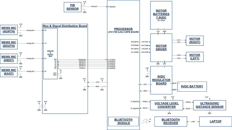
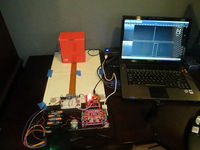
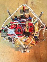
Figure 02 shows the overall hardware implementation of the design. Also included in this section are photos of the circuit card assemblies that were built to adapt the various sensors and power distribution.
Hardware Design [Tools Used]
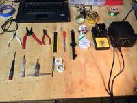
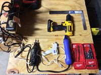
For students that do not have a lot of hands-on experience we have taken some photos of the tools we used to build the BM2000. In Figure 03 and Figure 04 you can see that we used:
- Soldering Tools
- Soldering Iron
- Solder
- Paste Flux(critical to obtain good solder flow leading to good solder joints)
- Desoldering wick and pump
- Helping hands with magnifying glass
- Hand Tools
- Diagonal cutters
- Needle Nose pliers
- Wire Stripers
- Razor Blade
- Spring loaded center punch(helps ensure drill bit stays in place when starting pilot holes
- 4-40 tap for the standoffs attached to the acrylic disks that were used to mount circuit boards
- Wire-wrap tool
- Metal file
- Square
- Drill bits
- Power Tools
- Power drill
- Dremel Tool
- Heat gun
- Glue gun glue(always comes in handy and great for insulating electronics)
Power
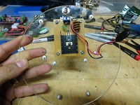
Figure 05 shows the 5V power regulator circuit that was bult using a 7805 Linear Regulator. The BM2000 uses 5V power to power the motor driver board logic circuits, the Ultrasonic sensor, and the SJSU LPC1758 development board.
Mux and Signal Distribution Board
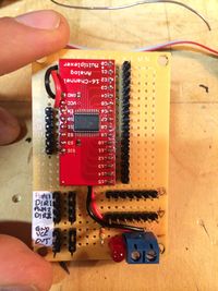
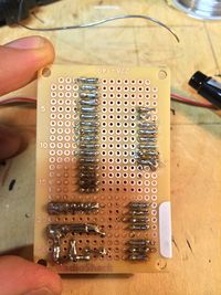
Figure 06 and Figure 07 show the Mux and Signal Distribution Board which is used to multiplex the MEMs sensors and a common connection point to interface the various sensors to the SJSU LPC1758 development board.
Passive Infrared Sensor
Figure 08 and Figure 09 show the Passive Infrared(PIR) Sensor board.
Motor Driver
Specifications:
  * 4 x Low Resistance FET “H” Bridges
  * Each Channel Rated for 4A Stall Current
  * Easy-to-Use Control Logic
  * Current Monitoring for Each Channel.
  * Quadrature Encoder Mixing Circuitry
  There are two power connectors on board.
  One is for 5V logic and the other is the motor supply.
  Be sure to turn on your logic supply before applying the power source for your motors.
  The board is rated for a maximum motor supply voltage of 12V.
  Control logic:
       The built in control logic allows each motor to be controlled by 2 pins. Driving the
       direction pin high or low will cause the motor to run forward or reverse. The PWM pin
       is used to control the motor speed. When this pin is low, the motor is off. When this pin
       is high the motor is at full power. To vary the speed of the motor this pin must be Pulse
       Width Modulated.
Sensor Pin Names and Descriptions:
   * Ch1 PWM
   * Ch1 Direction
   * Ch2 PWM
   * Ch2 Direction
Product website: https://www.sparkfun.com/products/11593 http://www.amazon.com/gp/product/B00AEOMUSM/ref=oh_details_o01_s00_i02?ie=UTF8&psc=1
Ultrasonic Distance Sensor Interface
Specifications:
   Power supply :5V DC
   Quiescent current : <2mA
   Effective angle: <15°
   Ranging distance : 2cm – 500 cm
   Resolution : 0.3 cm
Sensor Pin Names and Descriptions:
   Vcc = Positive Supply Voltage (5Vdc)
   Trig = Used to command the sensor to send out Ultrasonic signal
          (10usec TTL positive pulse required)
   Echo = The feedback signal that indicates when an object is detected
          (active high TTL pulse,  idle state low)
   Gnd = Ground
Note: Duration of echo high pulse is used to determine distance Distance = ((Duration of high level)*(Sonic :340m/s))/2 Based on our testing the echo response signal goes high within 456usec of trigger trigger signal going low
Product website: http://www.sainsmart.com/arduino-compatibles-1/sensor/ultrasonic-ranging-detector-mod-hc-sr04-distance-sensor.html
Figure 10 shows the setup used to test out the Ultrasonic Distance Sensor Interface. Measurements were taken to verify that the sensor accuracy was sufficient. For our application accuracy on the order of +/-6.0 inches was sufficient since we are using the sensor to prevent the robot from running into our four legged friend. The sensor operation is fairly simple. A 10 usec positive going TTL pulse is sent to the Trigger Input. This commands the sensor to begin sampling the sensor and generate a pulse on the Echo pin that is also a positive going TTL pulse. The pulse width of the Echo pulse is a function of the distance of the detected object. The software driver will measure the pulse width on a GPIO input and calculate the distance using the distance equation stated above in the Sensor Pin Names and Descriptions section.
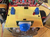
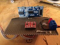
Figure 11 shows the top side of the Ultrasonic Sensor Board. This sensor was difficult to mount as is, so it was installed on a perf board that mounts to the bottom side of the lower level section of the BM2000. Also installed on the perf board are supporting electronics and a ribbon cable that is routed to the top level of the BM2000. On the top level the ribbon cable connects to the BM2000 Mux Board. None of the ultrasonic sensor signals are multiplexed. This board was used as a signal distribution point since it is in close proximity to the SJSU LPC1758 Development Board. Since the ultrasonic sensor requires 5V(TTL) logic signals, a logic level converter was used to interface the Trigger and Echo signals with our SJSU LPC1758 Development Board.
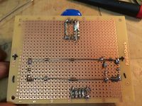
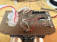
Figure 12 shows the bottom side of the Ultrasonic Sensor Board. Not the prettiest wire-wrap and soldering workmanship, but it got the job done.
Ultrasonic sensing was originally intended to protect the BM2000 from directly running into the dog or any other object once it senses the dog location and drives forward. The hardware and software for ultrasonic sensing was verified (albeit the sensing is slightly unreliable because the dog is not a rigid object). The functionality was removed from the BM2000 baseline architecture because the BM2000 was more fun when it drives at the dog so that she has to jump out of the way. The dog gets more riled up when the BM2000 shows some aggression back at her. The ultrasonic sensor function makes the BM2000 stop short of the dog, which in the eyes of the dog, makes the BM2000 appear tame. We include the detail of this portion of the project because we spent time on including this function despite removing it for the final product.
MEMs Microphone Sensors
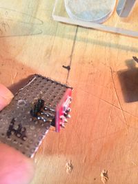
Figure 13 shows one of the MEMs Microphone sensors.
BarkMaster2000 Final Hardware Design Photos
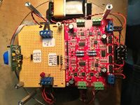
Figure 14 and Figure 15 shows the top view of the different levels of the BM2000.
Software Design
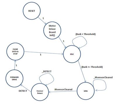
The software architecture is the equivalent of a state machine, where states are either represented as while loops or functions that are implemented once prior to jumping to the next state (see Figure below for the software state diagram).
The reset state is the beginning of the main program where initialization occurs. In the reset state the software initializes all GPIO, analog inputs, and PWM outputs. GPIO is used for the select lines to the mux, the input IR sensor and direction control for the motor controller board.
The reset state also uses the PINMODE register to utilize pull-downs on a few critical inputs. After the hardware had been integrated, it became apparent that electrical noise was influencing the reliability of the sensing. The electrical noise was problematic due to the high impedance of the sensor lines, especially during the mux switching times. It was determined that the internal pull down resistors located on the LPC1758 could help mitigate this problem. Therefore, the reset state also includes initialization of pull-down ‘resistors’ on the LPC1758 on certain critical inputs via the PINMODE register.
The motor driver initialization state is really a hardware function. The BM2000 must wait for the motor driver board to initialize before entering into the main routine. The code simply implements a delay to wait for hardware initialization.
Once the BM2000 enters into the IDLE state the device is actively listening for an ‘angry’ bark. The bark has to be of sufficient magnitude to be recognized as an angry bark. The software uses a pseudo mathematical integration for its filtering properties in order to make this determination. The following code shows how this is accomplished within a for loop.
       for (int i = 1; i < samplesTaken; i++)
       {
           barkRawValueTemp = adc0_get_reading(5);
           delay_ms(2);  // space out samples
           barkRawValue = barkRawValue + barkRawValueTemp;
       }
This simple code provides even spacing of signals and sums the total. The important attribute is that each sample is spaced about a sample time of 2ms. In integration, or more accurately in this case a Riemann Sum, the samples represent the height of rectangles that have width equal to the sample period. In this way the summation of each of these points is a crude approximation of the area under the curve, which is basically the ‘energy’ of the bark. If it were a true Riemann Sum, then we would have multiplied each point by its sample period (2ms in this case). However, it was deliberately excluded because this would add extra processing time between each sample that isn’t necessary. Since all sensors are polled at the same sample period, the actual duration between samples is not relevant. Adding all the samples together provides the ‘energy’ of the recorded sound. If this energy overcomes a experimentally derived threshold, then it is a legitimate bark. The variables under control are the threshold, the number of samples taken to be added in the integration technique, and the sample time. The period of the sample time is 2ms because we were able to measure the output of the MEMs devices on an oscilloscope and showed that the output contained a lot of high frequency content that could interfere with the results. We deliberately down sample as a filtering technique because in this situation the analog audio waveform shape isn’t what is important, but rather the amount of ‘energy’ in the bark. The threshold for determining the bark and the number of samples to be taken were determined through a trial and error process. Once audio detection is complete, the BM2000 will jump to the state that begins IR detection. However, through experiment it became clear that the dog likes it when the BM2000 starts spinning, so a mandatory spin time was added to make the BM2000 spin after every bark. The polling of analog inputs to the mux is performed by choosing the correct address of the sensor over GPIO. A function was named “muxChannelSelect” was created that would select the lines of the analog mux to poll the appropriate sensor. The function uses a simple switch statement where each case is one of the 16 input select permutations of the mux. The default case is address 0. The first step in detecting the dog after a bark and a prescribed spin time is to begin sweeping the room with the IR sensor. However, it was an unexpected attribute of the IR sensor hardware that the sensor output would remain high for several seconds after the last detection had occurred. The impact on the original software implementation was that the BM2000 would basically skip the IR sensing state after audio detection because it would immediately believe that the barking dog had been located. To overcome this hardware nuance, an additional while loop had to be added to ensure that the IR sensor was set low prior to looking to see if it has found the dog as it sweeps the room. The following code shows the polling technique to accomplish this task. while (IRsensorOut)
           {
               LD.setNumber(delayCode);
               IRsensorOut = !!(LPC_GPIO1->FIOPIN & (1<<30));
               delay_ms(100);
           }
After the IR sensor is polled to ensure that it is low before it goes high, the BM2000 simply polls the sensor to see when detection occurs. When a detect occurs the BM2000 jumps to the next state, shuts down the spinning, and puts both motors into forward drive for a prescribed amount of time. It is during this state that the original BM2000 design was going to have the ultrasonic sensing capability. However, as described above, this was removed because of difficulty with accurately sensing a non-rigid shape (dog), and because it took away from the overall fun of the toy if the BM2000 stops short of running into the dog. After driving forward the variables used for sensing are re-initialized to zero and the BM2000 enters back into the IDLE state for more bark sensing madness. Note that debugging on a motorized vehicle is difficult, especially when trying to determine whether the noise of the motors is interfering with the quality of the data. To simplify this task, a Bluetooth wireless transceiver was added to the design and printf commands are sent via Bluetooth to a laptop communication port. Much of the debugging commands have been removed from the original code.
Implementation
Implementing sensing of MEMs inputs is performed as below. Steps 1 -3 are one time only. 1. Initializing mux output to ADC input 2. Initializing the hardware inputs with pull-downs to minimize noise 3. Initializing address lines of mux 4. Calling function to correct address of MUX input (via GPIO) 5. Sampling mux at periodic intervals over prescribed number of samples 6. Summing all samples 7. Compare with threshold values Implementing the IR sensor is performed as below. Step 1 is only done once. 1. Initialize output of IR sensor has GPIO 2. Poll the IR sensor to determine if it is high when first looking a. If high, wait until IR sensor goes low 3. Poll IR sensor until it goes high Implementing the PWM motor control is performed as below. Steps 1 and 2 are one time only. 1. Initialize the PWM frequency 2. Initialize variables used for direction of the PWM motor board 3. Set direction of motor over GPIO 4. Set duty cycle of PWM output 5. Delay until time to stop or sensing has occurred
Testing & Technical Challenges
- Noise from MEMS sensor was causing issues with bark sensing
- Measured output on scope – lots of high frequency
- Did experiment with different wire lengths showing noise increase
- Used pull-downs within LPC1758 to reduce coupled noise
- Sampled MEMs devices at low frequency (via software) to reduce noise
- Acquiring data on a moving object
- Suspected onboard electronics corrupting sound data
- Needed to see sound outputs to debug while Barkmaster2000
- Added Bluetooth capability to get live sampling while operating
- Distance sensing
- Original intention was to sense distance and stop if it got too close
- Further testing showed that sensing would limit the movement too much
- More fun to have the Barkmaster2000 just drive right at the dog without stopping
- Narrowing the range of the IR sensor
- IR sensor would pick out a 180 degree field
- Taped the exterior of the sensor - small window for sensing
- Not 100% accurate but sufficient to entertain the dog
Conclusion
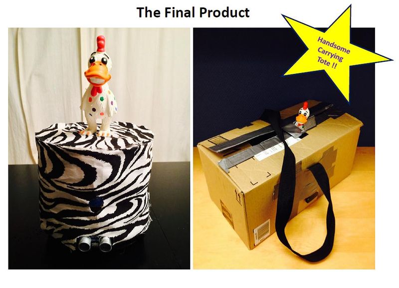
The project was a successful endeavor for the Barkmaster team. Our approach was to make an obtainable goal that required us to learn how to program the LPC1758 while incorporating new hardware functions that neither Patrick nor Bryan had used before. The code was intentionally kept as simple as possible to reach our obtainable goal. The audio sensing was definitely the most challenging of all the interfaces, requiring the most debugging time in both hardware and software. Overall, both members of the team enjoyed the project and the class. We have further plans to continue using the SJSU development board for fun projects that increase our engineering knowledge. The final product is shown below. The handsome carrying tote can be purchased with the Barkmaster2000 for an additional $56,000.
Project Presentation
Media:Barkmaster2000 demoDay (2).pptx
Project Video
Project Source Code
References
Acknowledgement
Any acknowledgement that you may wish to provide can be included here.
References Used
LPC17xx User Manual Rev.2-19 August 2010
