Difference between revisions of "F13: LED Display"
Proj user7 (talk | contribs) (→Hardware Fabrication Steps) |
Proj user7 (talk | contribs) (→Hardware Fabrication Steps) |
||
| Line 79: | Line 79: | ||
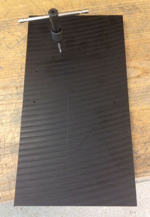
A piece of 1/2" Delrin sheet was obtained to hold the two boards and to give the AC wiring some strain relief. Holes for standoffs were drilled and tapped as shown in Figure 2. | A piece of 1/2" Delrin sheet was obtained to hold the two boards and to give the AC wiring some strain relief. Holes for standoffs were drilled and tapped as shown in Figure 2. | ||
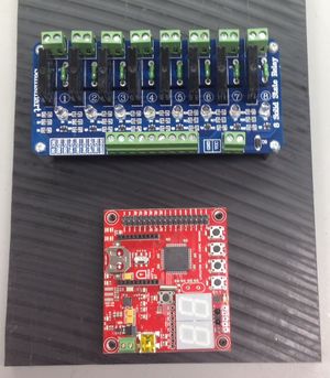
| − | [[File:LED_display- | + | The boards were then mounted (see Figure 3) to the Delrin with 3/4" tall Aluminum standoffs. The relay board was screwed down, since it would not need to be removed. The development board was held on with set screws for easy removal. |
| + | {| | ||
| + | | [[File:LED_display-drill_tap.jpg|thumb|Figure 2: Drilled and tapped holes]] | ||
| + | | [[File:LED_display-Mounted_boards.jpg|thumb|left|Figure 3: Mounted boards]] | ||
| + | |} | ||
| − | |||
| − | + | ||
| + | |||
=== Hardware Interface === | === Hardware Interface === | ||
Revision as of 19:21, 10 November 2013
Contents
Grading Criteria
- How well is Software & Hardware Design described?
- How well can this report be used to reproduce this project?
- Code Quality
- Overall Report Quality:
- Software Block Diagrams
- Hardware Block Diagrams
- Schematic Quality
- Quality of technical challenges and solutions adopted.
Project Title
A Moderately Fancy LED Display
Abstract
This project will control several strings of household LED lights (i.e. Christmas lights) via a microcontroller. The LED display will be synced to a song playback.
Objectives & Introduction
This project will need to be able to control several relays with the microcontroller. The development board's GPIO header pins (P2.0 - P2.7) will be used to bias the gate of a FET, which will in turn drive the relay coil. The ADC will sync up the playback of the song to the LED display. The ADC will wait for the first beat of the song, and then begin the program. The LED timing and channel useage will be manually programmed to make a visually appealing show.
Team Members & Responsibilities
This project is being completed by Mike Mellman. All responsibilities are his alone.
Schedule
| Task | Milestone? | Expected Duration | Actual Duration |
| Settle on project and approval by instructor | Y | 9/24 - 10/1 | 9/24 - 10/1 |
| Finalize channel count on dev and relay boards | 10/1 - 10/5 | 10/1 - 10/5 | |
| Identify vendors for parts | 10/1 - 10/5 | 10/1 - 10/5 | |
| Prepare proposal | 10/5 - 10/6 | 10/5 - 10/6 | |
| Final instructor approval | 10/8 | 10/8 | |
| Finalize circuit design | 10/8 - 10/15 | 10/8 - 10/12 | |
| Order online parts (long-lead from China) | Y | 10/8 - 10/15 | 10/12 |
| Buy parts from store | Y | 10/8 - 10/15 | 10/12 |
| Pick song for display | 10/8-10/15 | 10/13 | |
| Work on code for timing LEDs | 10/15 - 11/22 | ||
| Relay board in hand | 11/1 | 11/4 | |
| Build hardware setup | Y | 11/2 - 11/5 | |
| Lecture on ADC | 11/5 | 11/5 | |
| Write code to sync LEDs to song playback | 11/6 - 11/9 | ||
| Change LEDs to look good with song (for nice video) | 11/22 - 11/28 | ||
| Complete report | Y | 11/28 - 12/3 | |
| Project presentation | Y | 12/4 | 12/4 |
Parts List & Cost
Give a simple list of the cost of your project broken down by components. Do not write long stories here.
Design & Implementation
The design section can go over your hardware and software design. Organize this section using sub-sections that go over your design and implementation.
Hardware Design
Each GPIO pin biases the gate of a transistor on the relay board. The 5V battery source on the relay board then has a conductive path to power the relay coil. A schematic of a single channel is shown below in Figure xx.
Hardware Fabrication Steps
A piece of 1/2" Delrin sheet was obtained to hold the two boards and to give the AC wiring some strain relief. Holes for standoffs were drilled and tapped as shown in Figure 2.
The boards were then mounted (see Figure 3) to the Delrin with 3/4" tall Aluminum standoffs. The relay board was screwed down, since it would not need to be removed. The development board was held on with set screws for easy removal.
Hardware Interface
In this section, you can describe how your hardware communicates, such as which BUSes used. You can discuss your driver implementation here, such that the Software Design section is isolated to talk about high level workings rather than inner working of your project.
Software Design
Show your software design. For example, if you are designing an MP3 Player, show the tasks that you are using, and what they are doing at a high level. Do not show the details of the code. For example, do not show exact code, but you may show psuedocode and fragments of code. Keep in mind that you are showing DESIGN of your software, not the inner workings of it.
Implementation
This section includes implementation, but again, not the details, just the high level. For example, you can list the steps it takes to communicate over a sensor, or the steps needed to write a page of memory onto SPI Flash. You can include sub-sections for each of your component implementation.
Testing & Technical Challenges
Describe the challenges of your project. What advise would you give yourself or someone else if your project can be started from scratch again? Make a smooth transition to testing section and described what it took to test your project.
Include sub-sections that list out a problem and solution, such as:
Wifi Connection Issues
Many wifi connection issues were encountered. To solve this problem, a dedicated task was created to re-connect to wifi if the connection was ever lost.
Conclusion
Conclude your project here. You can recap your testing and problems. You should address the "so what" part here to indicate what you ultimately learnt from this project. How has this project increased your knowledge?
Project Video
Upload a video of your project and post the link here.
Project Source Code
Send me your zipped source code and I will upload this to SourceForge and link it for you.
References
Acknowledgement
Any acknowledgement that you may wish to provide can be included here.
References Used
List any references used in project.
Appendix
You can list the references you used.

