Difference between revisions of "S14: Virtual Dog"
Proj user16 (talk | contribs) |
(→Project Source Code) |
||
| (55 intermediate revisions by one other user not shown) | |||
| Line 1: | Line 1: | ||
| + | [[File:CmpE244_S14_vDog_angle.jpg|right|520px]]<br> | ||
| + | |||
== Project Title : Virtual Dog - An Object Following Robot == | == Project Title : Virtual Dog - An Object Following Robot == | ||
| + | <p style="text-indent: 1em; width: 700px; text-align: justify;"> | ||
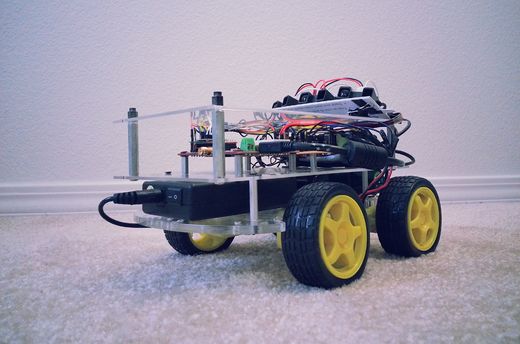
| + | One of our friend has a dog, who likes to play with remote control car. He used to run away from car when car approaches towards him, whereas if car runs away from him, he liked to follow the car! So we thought to make a toy which will do this job automatically. It will try to follow the object, but when object comes closer to it, it will move in opposite direction to maintain the predefined distance between object and itself. So, the name Virtual Dog! This concept can be used in many places, for creating many creative toys that will keep your kids and pets occupied, can be integrated with shopping carts, so that you’ll never need to carry you cart in the mall, the cart will follow you instead or can be integrated with vehicles, which will drive your vehicle automatically in heavy traffic. | ||
| + | </p> | ||
== Abstract == | == Abstract == | ||
| − | In this project | + | <p style="text-indent: 1em; width: 700px; text-align: justify;"> |
| + | In this project we built a device which is capable of tracking and following a particular object. This tracking and following is done in two dimensions, i.e. not just forward-backward movement, but left-right also. This is achieved with help of multiple distance sensors mounted on a robot, and a target reference object. Robot continuously monitors the position of target object, if position of target object changes, robot rearranges its position so as to maintain the desired relationship between them. | ||
| + | </p> | ||
== Objectives & Introduction == | == Objectives & Introduction == | ||
| − | The main objective is to build an object following robot, which will follow a particular object in 2-Dimension. To | + | <p style="text-indent: 1em; width: 700px; text-align: justify;"> |
| − | + | The main objective is to build an object following robot, which will follow a particular object in 2-Dimension. To achieve this we divided our design in two parts, viz., sensor module and motor module. | |
| + | </p> | ||
| + | <p style="text-indent: 1em; width: 700px; text-align: justify;"> | ||
| + | Sensor module reads values from sensor, normalizes them and runs an algorithm that decides the position of target object. Output from this algorithm is given to motor driver module. | ||
| + | </p> | ||
| + | <p style="text-indent: 1em; width: 700px; text-align: justify;"> | ||
| + | Motor driver module decides the speed and direction required to reposition robot, if required. It also generates appropriate PWM output to drive each individual motor so as to achieve resultant motion of a robot in desired direction with appropriate speed. | ||
| + | </p> | ||
| + | <p style="text-indent: 1em; width: 700px; text-align: justify;"> | ||
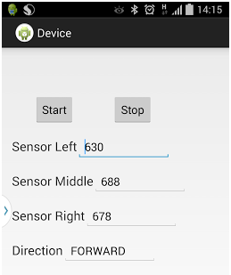
| + | We also built an android application interfaced with the robot via Bluetooth. This application can start/stop the robot and monitor realtime sensor outputs, as well as display decisions taken by our algorithm. | ||
| + | </p> | ||
=== Team Members & Responsibilities === | === Team Members & Responsibilities === | ||
* Hari | * Hari | ||
| − | ** Implemented | + | ** Implemented Sensor Driver, Algorithm to normalize Sensor values, and Android Application. |
* Manish | * Manish | ||
| − | ** Implemented | + | ** Implemented Central Control Logic, and FSM. |
* Viral | * Viral | ||
| − | ** Implemented | + | ** Implemented Motor Driver, Motor State Machine, and Bluetooth Driver. |
== Schedule == | == Schedule == | ||
| Line 34: | Line 51: | ||
| 3/23 | | 3/23 | ||
| Completed (3/30) | | Completed (3/30) | ||
| − | | Research on sensors took more time than expected due speed constrains of sensors conflicting with our requirement. Finally decided to move with IR proximity sensor. Sensors ordered. | + | | Research on sensors took more time than expected due to speed constrains of sensors conflicting with our requirement. Finally decided to move with IR proximity sensor. Sensors ordered. |
|- | |- | ||
! scope="row"| 3 | ! scope="row"| 3 | ||
| Line 74: | Line 91: | ||
! scope="row"| 9 | ! scope="row"| 9 | ||
| Android Application using Bluetooth | | Android Application using Bluetooth | ||
| − | | | + | | - |
| Completed (5/22) | | Completed (5/22) | ||
| − | | Developed an Android Application through which we can start and stop our robot and able to collect | + | | Developed an Android Application through which we can start and stop our robot and able to collect real-time data for sensor values as well as decisions taken by robot. |
|} | |} | ||
| Line 93: | Line 110: | ||
| 1 | | 1 | ||
| Preet | | Preet | ||
| − | | | + | | - |
| $80.00 | | $80.00 | ||
|- | |- | ||
| Line 107: | Line 124: | ||
| 4 | | 4 | ||
| HSC Electronics | | HSC Electronics | ||
| − | | | + | | - |
| $6.00 | | $6.00 | ||
|- | |- | ||
| Line 113: | Line 130: | ||
| Wheels | | Wheels | ||
| 4 | | 4 | ||
| − | | | + | | Pololu |
| − | | | + | | - |
| $8.00 | | $8.00 | ||
|- | |- | ||
| Line 121: | Line 138: | ||
| 1 | | 1 | ||
| Amazon | | Amazon | ||
| − | | | + | | - |
| $40 | | $40 | ||
|- | |- | ||
| Line 128: | Line 145: | ||
| 1 | | 1 | ||
| Amazon | | Amazon | ||
| − | | | + | | - |
| $25 | | $25 | ||
|- | |- | ||
! scope="row"| 7 | ! scope="row"| 7 | ||
| − | | | + | | L2938D (Motor Driver IC) |
| 2 | | 2 | ||
| HSC Electronic | | HSC Electronic | ||
| − | | | + | | - |
| $5.40 | | $5.40 | ||
|- | |- | ||
| Line 142: | Line 159: | ||
| 2 | | 2 | ||
| Walmart | | Walmart | ||
| − | | | + | | - |
| $12.00 | | $12.00 | ||
|- | |- | ||
! scope="row"| 9 | ! scope="row"| 9 | ||
| − | | Accessories ( | + | | Accessories (Jumper wires, Nut-Bolts, Prototype board, USB socket) |
| − | | | + | | - |
| − | | | + | | - |
| − | | | + | | - |
| $20.00 | | $20.00 | ||
|- | |- | ||
| Line 169: | Line 186: | ||
== Design & Implementation == | == Design & Implementation == | ||
| − | === Hardware Design === | + | === <u>Hardware Design</u> === |
| − | + | <table> | |
| − | <b>DC | + | <tr> |
| + | <td valign="top" align="justify" width=400px> | ||
| + | <b>System Block Diagram:</b> | ||
| + | <br> | ||
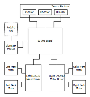
| + | The Hardware unit consist of three proximity sensors, SJOne board, four DC motors, bluetooth module, chassis, four wheels, and two batteries. All the three proximity sensors will measure their respective analog value and send it to the ADC pin of the SJOne board which will convert it to the digital value, the converted digital value will be utilized to determine the distance between the robot and the object. Based on the calculated distance the PWM value is determine for each DC motor, these PWM value is given as input to the DC motor via L293D IC. The Bluetooth device will read the value of the sensor from the SJOne board through UART and send it to the Android App which will display the real time value of the sensor as well as decision taken by robot. | ||
| + | </td> | ||
| + | <td> | ||
| + | [[File:CmpE244_S14_vDog_system_block_diagram.bmp|300px]] | ||
| + | </td> | ||
| + | </tr> | ||
| − | + | <tr> | |
| + | <td valign="top" align="justify"> | ||
| + | <b>Proximity Sensor:</b> | ||
| + | <br> | ||
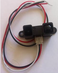
| + | This SHARP distance sensor bounces IR off objects to determine how far away they are. It returns an analog voltage that can be used to determine how close the nearest object is. These sensors are good for detection between 20cm-150cm. We are using three sensors for our project so that our robot can trace the position of object accurately in two dimensions. This sensor provide less influence on the colors of the reflected objects and reflectivity, due to optical triangle measuring method. There is no need of any external circuitry for this sensor. The recommended operating supply voltage for this sensor is from 4.5V to 5.5V. | ||
| + | </td> | ||
| + | <td> | ||
| + | [[File:CmpE244_S14_vDog_IR_sensor.png|200px]] | ||
| + | </td> | ||
| + | </tr> | ||
| − | <b> | + | <tr> |
| + | <td valign="top" align="justify"> | ||
| + | <b>DC Motor:</b> | ||
| + | <br> | ||
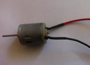
| + | We are using four DC motors for our project, with rating 5-12V operating voltage @ 0.16Amp, 2000RPM. We are using DC motor so that we can provide 360 degree rotation to our robot wheel as well as it help to drive the robot at a very high speed. DC Motor converts electric energy into mechanical energy. A DC Motor uses direct current - in other words, the direction of current flows in one direction. The speed of DC motors is controlled using Pulse Width Modulation (PWM), a technique of rapidly pulsing the power on and off. The percentage of time spent cycling the on/off ratio determines the speed of the motor. | ||
| + | </td> | ||
| + | <td> | ||
| + | [[File:CmpE244_S14_vDog_DC_motor.png|300px]] | ||
| + | </td> | ||
| + | </tr> | ||
| − | [[File: | + | <tr> |
| + | <td valign="top" align="justify"> | ||
| + | <b>L293D IC:</b> | ||
| + | <br> | ||
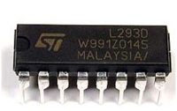
| + | L293D is a typical Motor driver or Motor Driver IC which allows DC motor to drive on either direction. L293D is a 16-pin IC which can control a set of two DC motors simultaneously in any direction. It means that you can control two DC motors with a single L293D IC. The L293D is designed to provide bidirectional drive currents of up to 600-mA at voltages from 4.5 V to 36 V. | ||
| + | </td> | ||
| + | <td> | ||
| + | [[File:CmpE244_S14_vDog_L293D.png|200px]] | ||
| + | </td> | ||
| + | </tr> | ||
| − | <b> | + | <tr> |
| + | <td valign="top" align="justify"> | ||
| + | <b>Bluetooth Module:</b> | ||
| + | <br> | ||
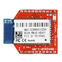
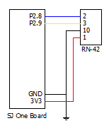
| + | The RN-42 is compatible with the Bluetooth versions 2 and below. The advantage of using this module is it's low power and at the same time can provide a good data rate. This provides a high performance on chip antenna where data rates upto 3Mbps are transferred. The disadvantage is that, it has a very less distance which is approximately 20 meters. There is a pull up circuit of 1k to the Vcc. This is provided so that if the input power supply has instability or tends to bounce which causes the that device to be damaged. There is separate pin allocated for the Factory Reset such that this comes into the picture when the module is misconfigured. The toggle of the specific GPIO pins indicate the status of the module. When toggled at 1Hz, the module is discoverable and is waiting for a connection. When at 10Hz, it made to change to the command mode. If it is very low, then module is already connected to another device over the bluetooth. | ||
| + | </td> | ||
| + | <td> | ||
| + | [[File:CmpE244_S14_vDog_bluetooth_device.png|200px]] | ||
| + | </td> | ||
| + | </tr> | ||
| − | + | </table> | |
| − | < | + | === <u>Hardware Interface</u> === |
| + | <table> | ||
| + | <tr> | ||
| + | <td valign="top" align="center"> | ||
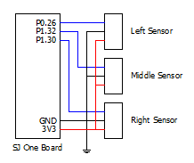
| + | Pin connections for IR Sensor through ADC:<br> | ||
| + | [[File:CmpE244_S14_vDog_sensor_connections.bmp|260px]] | ||
| + | </td> | ||
| + | <td valign="top" align="center"> | ||
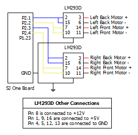
| + | Pin connections for Motor Driver using PWM:<br> | ||
| + | [[File:CmpE244_S14_vDog_motor_connections.bmp|320px]] | ||
| + | </td> | ||
| + | <td valign="top" align="center"> | ||
| + | Pin connections for Bluetooth Device:<br> | ||
| + | [[File:CmpE244_S14_vDog_bluetooth_connections.bmp|180px]] | ||
| + | </td> | ||
| + | </tr> | ||
| + | </table> | ||
| − | [[File: | + | === <u>Software Design</u> === |
| + | <table> | ||
| + | <tr> | ||
| + | <td> | ||
| + | [[File:CmpE244_S14_vDog_range_zones.bmp|300px]] | ||
| + | </td> | ||
| + | <td valign="top" align="justify" width=400px> | ||
| + | <b>Idea Behind Central Control Logic:</b> | ||
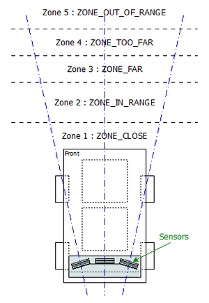
| + | As we are using IR sensor for measuring the distance between object and robot, we divided area in front of robot in 5 different zones based on the range of IR sensor. Our algorithm tries to maintain the distance between object and robot in such a way that the object will always be in the Zone2:ZONE_IN_RANGE of the robot. When object moves in Zone3:ZONE_FAR, robot will start moving towards the object with medium speed. When object moves in Zone4:ZONE_TOO_FAR, robot detects that and will advance towards object with increased speed until object is not in range with robot, i.e. object is not in Zone2:ZONE_IN_RANGE. When object moves too fast or suddenly disappears, then robot is not able to determine the position of the object. In such scenarios, object is considered to be in the Zone5:ZONE_NOT_IN_RANGE. In such case, robot will stop and alarm the user with buzzer and LED indicator. When object moves closer to robot, object is considered to be in Zone1:ZONE_CLOSE. In such case, algorithm tells motor driver to move robot in backward direction. In all the above said zones, sensor values from all three sensors are monitored, and based on our algorithm, robot also detects left and right movement of object with four different types, viz., Forward Left, Forward Right, Backward Left and Backward Right.</td> | ||
| + | </tr> | ||
| + | </table> | ||
| − | === | + | <table> |
| − | + | <tr> | |
| − | + | <td valign="top" align="justify" width=700px> | |
| − | < | + | <b>State Machine Diagram:</b> |
| − | + | <br> | |
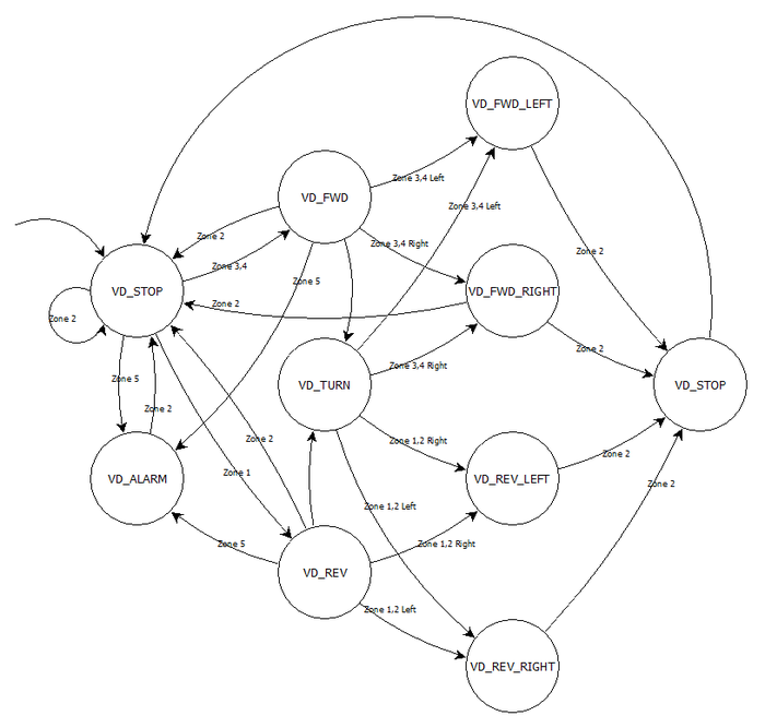
| − | [[File: | + | Based on the zones described earlier, we developed a state machine. Entire central logic relies on this state machine. Details of each state are described below: |
| − | < | + | * VD_STOP: This is the default state, when robot starts, it’s state first initialized to VD_STOP. When object is in Zone2, then also FSM is this state. In this state motor driver stops all the motors. If object moves to other zones, then FSM state is changed accordingly. |
| − | + | * VD_FWD: When object moves to Zone3 or Zone4, FSM is in this state. Based on the distance, motor driver drives the motors with appropriate speed when in this state. If object is detected in Zone2, FSM state is changed back to VD_STOP. If object suddenly disappears from middle sensor, FSM state is changed to VD_TURN. | |
| − | + | * VD_REV: When object moves to Zone1, FSM is in this state. In this state, motor driver generates PWM signal in such a way that robot will move backwards. If object is detected in Zone2, FSM state is changed back to VD_STOP. If object suddenly disappears from middle sensor, FSM state is changed to VD_TURN. | |
| + | </td> | ||
| + | </tr> | ||
| + | <tr> | ||
| + | <td> | ||
| + | [[File:CmpE244_S14_vDog_state_machine.bmp|700px]] | ||
| + | </td> | ||
| + | </tr> | ||
| + | <tr> | ||
| + | <td valign="top" align="justify" width=700px> | ||
| + | * VD_FWD_LEFT: If object is detected in Zone3 or Zone4 of left sensor, FSM is in this state. In this state, motor driver generates PWM signal in such a way that robot will take left turn in forward direction. Robot will remain in this state until object is not detected back in Zone2 or Zone3 or Zone4 of middle sensor. | ||
| + | * VD_FWD_RIGHT: If object is detected in Zone3 or Zone4 of right sensor, FSM is in this state. In this state, motor driver generates PWM signal in such a way that robot will take right turn in forward direction. Robot will remain in this state until object is not detected back in Zone2 or Zone3 or Zone4 of middle sensor. | ||
| + | * VD_REV_LEFT: If object is detected in Zone1 or Zone2 of right sensor, FSM is in this state. In this state, motor driver generates PWM signal in such a way that robot will take left turn in backward direction. Robot will remain in this state until object is not detected back in Zone1 or Zone2 or Zone3 or Zone4 of middle sensor. | ||
| + | * VD_REV_RIGHT: If object is detected in Zone1 or Zone2 of left sensor, FSM is in this state. In this state, motor driver generates PWM signal in such a way that robot will take right turn in backward direction. Robot will remain in this state until object is not detected back in Zone1 or Zone2 or Zone3 or Zone4 of middle sensor. | ||
| + | * VD_TURN: When object suddenly disappears from middle sensor, FSM is in this state. In this state, motor driver stops all the motors. FSM remains in this state until object is detected by either of the sensor. Based on which sensor detects the object, FSM state is changed to appropriate state. | ||
| + | * VD_ALARM: If any other object/obstacle appears suddenly in between target object and robot, FSM is in this state. Motor driver stops all motors, and user is alarmed with the help of buzzer and blinking LED indicator. | ||
| + | </td> | ||
| + | </tr> | ||
| + | </table> | ||
| − | + | <table> | |
| − | + | <tr> | |
| − | + | <td width=300px align="center"> | |
| − | < | ||
| − | < | ||
[[File:CmpE244_S14_vDog_flowchart_startup.bmp]] | [[File:CmpE244_S14_vDog_flowchart_startup.bmp]] | ||
| + | </td> | ||
| + | <td valign="top" align="justify" width=400px> | ||
| + | <b>Initialization:</b> | ||
<br> | <br> | ||
| − | On | + | On start process mainly does the initialization job. It initializes ADC pins (P0.26, P1.31, P1.30) that are used by IR sensors. Then PWM pins P2.1 through P2.4 are initialized for motor driver. We use GPIO to sound the buzzer, so GPIO pin P1.23 is configured as output in the init process. We use Bluetooth to connect to android device. Bluetooth device is connected via UART2 on the board. So init process also contains code part to init UART2 for Bluetooth device. After everything is set, three tasks start running, viz., sensor task, motor task and Bluetooth task. Sensor task continuously reads the sensor values, normalizes them and invokes our algorithm/FSM. Motor task generates appropriate PWM signals based on the current FSM state. Bluetooth task communicates with Android Application. |
| − | < | + | </td> |
| − | < | + | </tr> |
| + | |||
| + | <tr> | ||
| + | <td width=300px align="center"> | ||
[[File:CmpE244_S14_vDog_flowchart_sensor.bmp]] | [[File:CmpE244_S14_vDog_flowchart_sensor.bmp]] | ||
| + | </td> | ||
| + | <td valign="top" align="justify" width=400px> | ||
| + | <b>Sensor Driver:</b> | ||
<br> | <br> | ||
| − | In the Sensor Driver Task, the sensor values from all the three proximity sensors are read. They are normalized by using calculating the | + | In the Sensor Driver Task, the sensor values from all the three proximity sensors are read. They are normalized by using calculating the median of the previous 30 sensor values. Based on this, the object position is determined. If the object is located in the Zone 1 of the middle sensor, then the finite state machine is changed to reverse. The robot moves until the original position is achieved. If the object is located in the Zone 3 and Zone 4 of the middle sensor, then finite state machine is moved to the Forward state which causes the robot to move forward. If the left sensor detects the object in Zone 1 and Zone 2, the finite state machine is changed to reverse right. This moves the robot in the reverse right direction causing the direction of the robot indirectly to turn left. If the right sensor detects the object in Zone 1 and Zone 2, and the finite state machine is moved to the reverse left. This causes to change the direction of the robot indirectly to the right. If the left sensor detects the object in Zone 3 and Zone 4, the finite state machine is changed to forward left. This moves the robot in the forward and left direction causing the direction of the robot to turn left. If the right sensor detects the object in Zone 3 and Zone 4, the finite state machine is moved to the forward right. This causes to change the direction of the robot to the right. Thus based on the sensor values, the next stage of the Finite State Machine is decided and robot is move to that particular zone. |
| − | < | + | </td> |
| − | < | + | </tr> |
| + | |||
| + | <tr> | ||
| + | <td width=300px align="center"> | ||
[[File:CmpE244_S14_vDog_flowchart_motor.bmp]] | [[File:CmpE244_S14_vDog_flowchart_motor.bmp]] | ||
| + | </td> | ||
| + | <td valign="top" align="justify" width=400px> | ||
| + | <b>Motor Driver:</b> | ||
<br> | <br> | ||
| − | In the Motor Driver task, the finite state machine is read for each entry of the sensor data. Based on the state machine the Robot decides on the direction to move. If the decision made is forward, then the front two wheels which are connected to the driver are made to move. This causes the device to move forward. If it is forward left, then the front left | + | In the Motor Driver task, the finite state machine is read for each entry of the sensor data. Based on the state machine the Robot decides on the direction to move. If the decision made is forward, then the front two wheels which are connected to the driver are made to move. This causes the device to move forward. If it is forward left, then the front left wheel speed is decreased. This causes the device to turn left. If it is forward right, then the front right wheel speed is decreased. This causes the device to turn left. If the decision made is reverse, the wheels are made to rotate in the opposite direction. If it is reverse left, then the back left wheel direction is opposite and the speed is decreased. This causes the device to turn reverse left. If it is reverse right, then the back right wheel rotates in the opposite direction and the speed is decreased. This causes the device to turn reverse right. With the help of all the decisions, the Robot can be made to rotate 360 degree making the Robot to detect the object’s range and moving in appropriate direction. Finally, after Robot has moved such that the object comes into the ZONE_2, all the state machines are reset. This loop occurs until there is an indicator received telling the Robot to stop. |
| + | </td> | ||
| + | </tr> | ||
| + | </table> | ||
| − | === | + | <table> |
| − | <b> | + | <tr> |
| − | + | <td valign="top" align="justify" width=340px> | |
| − | + | <b>Virtual DOG Android Application:</b> | |
| − | + | <br> | |
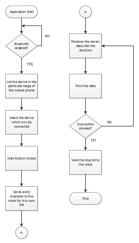
| − | + | The Android application helps in communicating with the Bluetooth module. The Bluetooth module is RN- 42. This module is directly placed in the location given for the zigbee module on the LPC board. Communication between the devices is full duplex. The initiation and the termination of the robot is controlled from the Android application. | |
| − | + | <br> | |
| − | + | On opening the application, the Bluetooth has to be turned ON. There are two Buttons for turning the Bluetooth ON and OFF. For the Bluetooth to be turned ON, permissions is required from the User. If the authentication is performed, then the devices which are available in the range of the Bluetooth module are listed down using the discovery method of the device. The Module’s name is selected in the mobile. The devices are paired together using a key. The key provides the security feature over the transmission and reception. | |
| − | + | <br> | |
| − | + | There are two buttons. The ‘START’ and ‘STOP’ button which indicate the robot to turn ON and OFF. This button is created in the XML. This language is used to build the UI functionalities. On clicking the START button, data is written to the Robot in order to indicate the Start status. The robot starts sensing and send back the values along with the direction in which it moves. This is sent in the form of a metadata, so that the time taken for transmitting is less. This improves the performance. The Metadata which comprises of the sensor values and the direction is received until the stop button is pressed. A separate data is written for stopping the data. The robot stops on receiving this data. | |
| − | + | <br> | |
| − | + | In order to connect with the robot faster, a separate list has been created which maintains the list of the paired devices. This will show the devices which were connected previously. | |
| − | + | <br> | |
| − | + | There is a new fragment (page) created from the MainActivity which is created and the device is opened with that new fragment. On successful completion of the pairing, there are some threads which are made to run in the background. On creation of the instance of the new fragment page, a thread to read the data on the output stream runs as one of the background process. This buffer which is read should happen continuously until there is ‘\n’ or ‘\r’ character is read. If it read, then the data from the UART of the module is read. | |
| − | + | </td> | |
| + | <td width=400px align="center"> | ||
| + | [[File:CmpE244_S14_vDog_android_flowchart.png]] | ||
| + | </td> | ||
| + | </tr> | ||
| + | </table> | ||
| − | < | + | === <u>Implementation</u> === |
| − | |||
| − | |||
| − | |||
| − | <b> | + | <br><b>Actual Implementation Images:</b><br> |
| − | + | <table> | |
| − | < | + | <tr> |
| − | + | <td valign="top" align="center"> | |
| − | + | Front View:<br> | |
| − | + | [[File:CmpE244_S14_vDog_front_view.jpg|360px]] | |
| − | + | </td> | |
| − | + | <td valign="top" align="center"> | |
| − | + | Side View:<br> | |
| − | + | [[File:CmpE244_S14_vDog_side_view.png|360px]] | |
| − | + | </td> | |
| − | + | <td valign="top" align="center"> | |
| − | < | + | Top View:<br> |
| − | + | [[File:CmpE244_S14_vDog_top_view.jpg|400px]] | |
| − | + | </td> | |
| − | + | </tr> | |
| − | + | </table> | |
| − | |||
| − | < | ||
| − | |||
| − | |||
| − | <b> | + | <br><b>Application Screenshots:</b><br> |
| − | <br>< | + | <table> |
| − | + | <tr> | |
| − | < | + | <td valign="top" align="center"> |
| − | + | [[File:CmpE244_S14_vDog_android_app_01.png]] | |
| − | < | + | </td> |
| − | [[File: | + | <td valign="top" align="center"> |
| − | < | + | [[File:CmpE244_S14_vDog_android_app_02.png]] |
| − | + | </td> | |
| − | < | + | </tr> |
| − | + | </table> | |
| − | < | ||
| − | |||
| − | <br><b> | + | <br><b>LED Conventions:</b><br> |
| − | [[File: | + | <table> |
| + | <tr> | ||
| + | <td valign="top" align="center"> | ||
| + | [[File:CmpE244_S14_vDog_vd_stop.gif|200px]] | ||
| + | </td> | ||
| + | <td valign="top" align="justify" width=500px> | ||
| + | When 1st and 4th LED are blinking, it indicates that object is in range, i.e. Zone2 and FSM state is VD_STOP. | ||
| + | </td> | ||
| + | </tr> | ||
| + | <tr> | ||
| + | <td valign="top" align="center"> | ||
| + | [[File:CmpE244_S14_vDog_vd_fwd.bmp|200px]] | ||
| + | </td> | ||
| + | <td valign="top" align="justify" width=500px> | ||
| + | When 2nd and 3rd LED glows continuously, it indicates that object has moved forward, i.e. in Zone3/Zone4 and FSM state is VD_FWD. | ||
| + | </td> | ||
| + | </tr> | ||
| + | <tr> | ||
| + | <td valign="top" align="center"> | ||
| + | [[File:CmpE244_S14_vDog_vd_rev.bmp|200px]] | ||
| + | </td> | ||
| + | <td valign="top" align="justify" width=500px> | ||
| + | When 1st and 4th LED glows continuously, it indicates that object is coming closer, i.e. in Zone1 and FSM state is VD_REV. | ||
| + | </td> | ||
| + | </tr> | ||
| + | <tr> | ||
| + | <td valign="top" align="center"> | ||
| + | [[File:CmpE244_S14_vDog_vd_turn.gif|200px]] | ||
| + | </td> | ||
| + | <td valign="top" align="justify" width=500px> | ||
| + | When 1st and 4th LED blinks, it indicates that object is taking turn, and robot is trying to figure out where the object has turned and FSM state is VD_TURN. If robot is not able to find out turned object, it means that object has moved out of range. | ||
| + | </td> | ||
| + | </tr> | ||
| + | <tr> | ||
| + | <td valign="top" align="center"> | ||
| + | [[File:CmpE244_S14_vDog_vd_fwdleft.bmp|200px]] | ||
| + | </td> | ||
| + | <td valign="top" align="justify" width=500px> | ||
| + | When 1st and 2nd LED glows continuously, it indicates that object is turning to left and FSM state is VD_FWD_LEFT. | ||
| + | </td> | ||
| + | </tr> | ||
| + | <tr> | ||
| + | <td valign="top" align="center"> | ||
| + | [[File:CmpE244_S14_vDog_vd_fwdright.bmp|200px]] | ||
| + | </td> | ||
| + | <td valign="top" align="justify" width=500px> | ||
| + | When 3rd and 4th LED glows continuously, it indicates that object is turning to right and FSM state is VD_FWD_RIGHT. | ||
| + | </td> | ||
| + | </tr> | ||
| + | <tr> | ||
| + | <td valign="top" align="center"> | ||
| + | [[File:CmpE244_S14_vDog_vd_revleft.bmp|200px]] | ||
| + | </td> | ||
| + | <td valign="top" align="justify" width=500px> | ||
| + | When only 1st LED glows continuously, it indicates that object is turning to left but in backward direction and FSM state is VD_REV_LEFT. | ||
| + | </td> | ||
| + | </tr> | ||
| + | <tr> | ||
| + | <td valign="top" align="center"> | ||
| + | [[File:CmpE244_S14_vDog_vd_revright.bmp|200px]] | ||
| + | </td> | ||
| + | <td valign="top" align="justify" width=500px> | ||
| + | When only 4th LED glows continuously, it indicates that object is turning to right but in backward direction and FSM state is VD_REV_RIGHT. | ||
| + | </td> | ||
| + | </tr> | ||
| + | <tr> | ||
| + | <td valign="top" align="center"> | ||
| + | [[File:CmpE244_S14_vDog_vd_alarm.gif|200px]] | ||
| + | </td> | ||
| + | <td valign="top" align="justify" width=500px> | ||
| + | When all LEDs blink fast, it indicates that some obstacle has detected and FSM state is VD_ALARM. | ||
| + | </td> | ||
| + | </tr> | ||
| + | </table> | ||
| − | <b> | + | == Testing & Technical Challenges == |
| − | + | <b>Normalization Algorithm:</b><br> | |
| − | [[File: | + | <p style="text-indent: 1em; width: 700px; text-align: justify;"> |
| − | + | Values retrieved from sensor are not stable. So we required to develop an algorithm that will give stable values from sensor. It should also remove spikes. We experimented a lot with this regard and finally developed an algorithm that gives fairly stable value of sensor without hampering the performance. Following graphs shows the Experiment results: | |
| − | [[File: | + | <br> |
| − | + | [[File:CmpE244_S14_vDog_actual_sensor.png|700px]] | |
| − | [[File: | + | <br> |
| + | Above graph shows experimental results of actual sensor values, when object is moved from right to left. It is clearly visible in the graph that values are not stable and also has many spikes. | ||
| + | <br> | ||
| + | [[File:CmpE244_S14_vDog_mean_sensor.png|700px]] | ||
| + | <br> | ||
| + | Above graph shows experimental results of mean/average of past 30 values of sensor. These values are fairly stable, but it does not help to detect object if object moves very fast. | ||
| + | <br> | ||
| + | [[File:CmpE244_S14_vDog_median_sensor.png|700px]] | ||
| + | <br> | ||
| + | Above graph shows experimental results of median of past 30 values. These are the most stable value that we could find out. So we used median to calculate sensor values, and used these values in our algorithm. | ||
| + | </p> | ||
| − | |||
<b>Motor Selection:</b><br> | <b>Motor Selection:</b><br> | ||
| − | Stepper Motor:<br> | + | <i>Stepper Motor:</i><br> |
| + | <p style="text-indent: 1em; width: 700px; text-align: justify;"> | ||
Initially we plan to use the Stepper motor with our DC motor so that we can control the position of our robot very precisely. As the servo motor that we plan to use is very heavy due to which our chassis weight get increased to a extreme level, and there is torque degradation at higher speed in stepper motor which is not desirable for our project so we plan to drop the use of stepper motor.<br> | Initially we plan to use the Stepper motor with our DC motor so that we can control the position of our robot very precisely. As the servo motor that we plan to use is very heavy due to which our chassis weight get increased to a extreme level, and there is torque degradation at higher speed in stepper motor which is not desirable for our project so we plan to drop the use of stepper motor.<br> | ||
| − | Servo Motor:<br> | + | </p> |
| + | <i>Servo Motor:</i><br> | ||
| + | <p style="text-indent: 1em; width: 700px; text-align: justify;"> | ||
Initially we plan to use the Servo motor instead of DC motor for our project so that we can provide a high torque to our robot wheels, but due to some disadvantage of servo motor like it continue to draw a high current when it is stuck at particular position make it undesirable for our project.<br> | Initially we plan to use the Servo motor instead of DC motor for our project so that we can provide a high torque to our robot wheels, but due to some disadvantage of servo motor like it continue to draw a high current when it is stuck at particular position make it undesirable for our project.<br> | ||
| − | DC Motor:<br> | + | </p> |
| + | <i>DC Motor:</i><br> | ||
| + | <p style="text-indent: 1em; width: 700px; text-align: justify;"> | ||
Finally we select the DC motor instead of using Stepper motor and Servo Motor. There are some advantages of DC motor like they can run at very high RPM value, provide full rotation , continue to rotate until power is removed, can be easily controlled using PWM. This advantage of DC motor matches with the requirement of the motor that we are looking for our project.<br> | Finally we select the DC motor instead of using Stepper motor and Servo Motor. There are some advantages of DC motor like they can run at very high RPM value, provide full rotation , continue to rotate until power is removed, can be easily controlled using PWM. This advantage of DC motor matches with the requirement of the motor that we are looking for our project.<br> | ||
| + | </p> | ||
<b>Sensor Selection:</b><br> | <b>Sensor Selection:</b><br> | ||
| − | Nordic Wi-Fi:<br> | + | <i>Nordic Wi-Fi:</i><br> |
| − | Initially we plan to use Nordic Wi-Fi present on our SJ One board to calculate the distance between robot and the object so that accordingly we can change the position of the robot. When we perform the experiment between | + | <p style="text-indent: 1em; width: 700px; text-align: justify;"> |
| − | Ultrasonic Sensor:<br> | + | Initially we plan to use Nordic Wi-Fi present on our SJ One board to calculate the distance between robot and the object so that accordingly we can change the position of the robot. When we perform the experiment between two Nordic Wi-Fi and tried calculating the distance between them the outcome result were not favorable, we were getting negligible change in the value when we change the position of one Wi-Fi module with respect to other. The outcome results were not desirable for our project so we drop the idea of using the Wi-Fi module.<br> |
| − | After getting the undesirable result from Wi-Fi we plan to use ultrasonic sensor to calculate the distance between the object and robot. When we perform the experiment the outcome result were not | + | </p> |
| − | Proximity Sensor:<br> | + | <i>Ultrasonic Sensor:</i><br> |
| − | We than plan to use the proximity sensor to calculate the distance between the object and robot. The proximity sensor we used to perform the experiment has a range of | + | <p style="text-indent: 1em; width: 700px; text-align: justify;"> |
| + | After getting the undesirable result from Wi-Fi we plan to use ultrasonic sensor to calculate the distance between the object and robot. When we perform the experiment the outcome result were not favorable, though the range of ultrasonic sensor was too good but the beam angle it generates to detect the object which come under its range was too high due to which it was able to detect a large number of object, so we were not able to calculate the exact distance between the original object and the robot. So we plan to drop the idea of using Ultrasonic Sensor.<br> | ||
| + | </p> | ||
| + | <i>Proximity Sensor:</i><br> | ||
| + | <p style="text-indent: 1em; width: 700px; text-align: justify;"> | ||
| + | We than plan to use the proximity sensor to calculate the distance between the object and robot. The proximity sensor we used to perform the experiment has a range of 20 cm to 150 cm, the outcome result from the experiment were favorable. We were able to calculate the exact distance between the robot and the object. So we decide to use the proximity sensor for our project to calculate the distance between robot and object.<br> | ||
| + | </p> | ||
<b>Motor Calibration Issue:</b><br> | <b>Motor Calibration Issue:</b><br> | ||
| + | <p style="text-indent: 1em; width: 700px; text-align: justify;"> | ||
As we decided to use DC motor for our project by performing a number of experiments, we plan to use 4 DC motor one for each wheel of the robot. After connecting DC motor to the wheels of the robot we check the alignment of all the four wheels, if they were not alignment we make all of them align by performing a number of hit and trial methods. The next issue is to run each motor at different speed at the same input given voltage so that we can control and move our robot in any direction. All the four motor speed is control individually by calculating the separate PWM value for each motor.<br> | As we decided to use DC motor for our project by performing a number of experiments, we plan to use 4 DC motor one for each wheel of the robot. After connecting DC motor to the wheels of the robot we check the alignment of all the four wheels, if they were not alignment we make all of them align by performing a number of hit and trial methods. The next issue is to run each motor at different speed at the same input given voltage so that we can control and move our robot in any direction. All the four motor speed is control individually by calculating the separate PWM value for each motor.<br> | ||
| + | </p> | ||
<b>Sensor Calibration Issue:</b><br> | <b>Sensor Calibration Issue:</b><br> | ||
| − | As we decide to use proximity sensor for our project we have to solve a number of calibration issue related with this sensor. The first thing is we have to decide the number of sensor required for our project. We decided to begin our experiment using three sensors, the next thing we have to decide is the position where we can place these sensor on our robot. After performing a lot of experiment we found that if our target object comes in a range less than 20cm from our robot all the sensor start throwing | + | <p style="text-indent: 1em; width: 700px; text-align: justify;"> |
| + | As we decide to use proximity sensor for our project we have to solve a number of calibration issue related with this sensor. The first thing is we have to decide the number of sensor required for our project. We decided to begin our experiment using three sensors, the next thing we have to decide is the position where we can place these sensor on our robot. After performing a lot of experiment we found that if our target object comes in a range less than 20cm from our robot all the sensor start throwing some garbage value. So we decided to place the sensor at the back of robot with their face facing front so that the sensor will not through garbage values if the target object is very close to the robot. Now we have to decide the angle at which our sensor must be placed so that it can detect the target object anywhere between the angles of 0 to 180 degree. So after performing a number of experiments we place our three sensors at 45, 90 and 135 degree. After placing the sensor at the proper position the next thing we have to determine is the distance between the object and the robot. For this we use the normalization method on the sensor value so that we can predict the correct distance between the object and the robot.<br> | ||
| + | </p> | ||
<b>Android Application Issue:</b><br> | <b>Android Application Issue:</b><br> | ||
| + | <p style="text-indent: 1em; width: 700px; text-align: justify;"> | ||
Operations involving the UI have the high Priority in the Android. Because of this, Updating the text Box with the sensor values and the direction will throw an IOexception. Because of this the application crashes.<br> | Operations involving the UI have the high Priority in the Android. Because of this, Updating the text Box with the sensor values and the direction will throw an IOexception. Because of this the application crashes.<br> | ||
Solution: Let the thread involving the receive function be executing as the background process and the UI update shall happen only after the execution of the receiving function. <br> | Solution: Let the thread involving the receive function be executing as the background process and the UI update shall happen only after the execution of the receiving function. <br> | ||
Establishing the initial pairing between the devices caused some faults such as socket was not open or already read. <br> | Establishing the initial pairing between the devices caused some faults such as socket was not open or already read. <br> | ||
Solution: This was due to the sudden termination of the previous socket connection. The Socket has to be closed on Application exit, on all the catch exceptions and any sudden termination. <br> | Solution: This was due to the sudden termination of the previous socket connection. The Socket has to be closed on Application exit, on all the catch exceptions and any sudden termination. <br> | ||
| + | </p> | ||
== Conclusion == | == Conclusion == | ||
| − | The Virtual Dog was a very challenging and research oriented project. Detailed analysis were made on various sensors while trying to implement the project. | + | <p style="text-indent: 1em; width: 700px; text-align: justify;"> |
| + | The Virtual Dog was a very challenging and research oriented project. Detailed analysis were made on various sensors while trying to implement the project. The project was built on a small scale. This would work as a prototype to build the applications such as shopping cart following a person in crowded areas such as the grocery stores etc. | ||
| + | </p> | ||
=== Project Video === | === Project Video === | ||
| − | + | <p style="text-indent: 1em; width: 700px; text-align: justify;"> | |
| + | http://youtu.be/njPgVcvl1cQ | ||
| + | </p> | ||
=== Project Source Code === | === Project Source Code === | ||
| − | + | * [https://sourceforge.net/projects/sjsu/files/CmpE244_SJSU_S2014/ Sourceforge source code link] | |
== References == | == References == | ||
=== Acknowledgement === | === Acknowledgement === | ||
| − | The hardware components were made available from Amazon,Sparkfun, Adafruit. Thanks to Preetpal Kang for providing right guidance for our project. | + | <p style="text-indent: 1em; width: 700px; text-align: justify;"> |
| + | The hardware components were made available from Amazon, Sparkfun, Adafruit. Thanks to Preetpal Kang for providing right guidance for our project. | ||
| + | </p> | ||
=== References Used === | === References Used === | ||
| + | <p style="width: 700px; text-align: justify;"> | ||
[http://www.nxp.com/documents/data_sheet/LPC1769_68_67_66_65_64_63.pdf LPC_USER_MANUAL] <br> | [http://www.nxp.com/documents/data_sheet/LPC1769_68_67_66_65_64_63.pdf LPC_USER_MANUAL] <br> | ||
[http://www.mouser.com/catalog/specsheets/rn-42-ds-v2.31r.pdf RN-42 Data Sheet]<br> | [http://www.mouser.com/catalog/specsheets/rn-42-ds-v2.31r.pdf RN-42 Data Sheet]<br> | ||
| Line 333: | Line 558: | ||
[http://www.ti.com/lit/ds/symlink/l293d.pdf L293D Data Sheet] <br> | [http://www.ti.com/lit/ds/symlink/l293d.pdf L293D Data Sheet] <br> | ||
[http://sharp-world.com/products/device/lineup/data/pdf/datasheet/gp2y0a02_e.pdf IR Sensor Data Sheet] <br> | [http://sharp-world.com/products/device/lineup/data/pdf/datasheet/gp2y0a02_e.pdf IR Sensor Data Sheet] <br> | ||
| + | </p> | ||
Latest revision as of 23:42, 6 August 2014
Contents
Project Title : Virtual Dog - An Object Following Robot
One of our friend has a dog, who likes to play with remote control car. He used to run away from car when car approaches towards him, whereas if car runs away from him, he liked to follow the car! So we thought to make a toy which will do this job automatically. It will try to follow the object, but when object comes closer to it, it will move in opposite direction to maintain the predefined distance between object and itself. So, the name Virtual Dog! This concept can be used in many places, for creating many creative toys that will keep your kids and pets occupied, can be integrated with shopping carts, so that you’ll never need to carry you cart in the mall, the cart will follow you instead or can be integrated with vehicles, which will drive your vehicle automatically in heavy traffic.
Abstract
In this project we built a device which is capable of tracking and following a particular object. This tracking and following is done in two dimensions, i.e. not just forward-backward movement, but left-right also. This is achieved with help of multiple distance sensors mounted on a robot, and a target reference object. Robot continuously monitors the position of target object, if position of target object changes, robot rearranges its position so as to maintain the desired relationship between them.
Objectives & Introduction
The main objective is to build an object following robot, which will follow a particular object in 2-Dimension. To achieve this we divided our design in two parts, viz., sensor module and motor module.
Sensor module reads values from sensor, normalizes them and runs an algorithm that decides the position of target object. Output from this algorithm is given to motor driver module.
Motor driver module decides the speed and direction required to reposition robot, if required. It also generates appropriate PWM output to drive each individual motor so as to achieve resultant motion of a robot in desired direction with appropriate speed.
We also built an android application interfaced with the robot via Bluetooth. This application can start/stop the robot and monitor realtime sensor outputs, as well as display decisions taken by our algorithm.
Team Members & Responsibilities
- Hari
- Implemented Sensor Driver, Algorithm to normalize Sensor values, and Android Application.
- Manish
- Implemented Central Control Logic, and FSM.
- Viral
- Implemented Motor Driver, Motor State Machine, and Bluetooth Driver.
Schedule
| Week# | Task | Estimated Completion Date |
Status | Notes |
|---|---|---|---|---|
| 1 | Order Parts | 3/16 | Partially Completed | Not finalized with sensor for distance measurement. Ordered other parts. |
| 2 | Sensor Study | 3/23 | Completed (3/30) | Research on sensors took more time than expected due to speed constrains of sensors conflicting with our requirement. Finally decided to move with IR proximity sensor. Sensors ordered. |
| 3 | Sensor Controller Implementation | 3/30 | Completed (4/6) | Three sensors interfaced with on board ADC pins. Controller implemented to determine direction of movement based on those three sensors |
| 4 | Servo and Stepper Motor Controller Implementation | 4/6 | Completed (4/6) | Initially planned to use stepper motor for steering and servo to move robot. But due to power constraints, decided to use DC motors to make a 4WD robot. Controller implemented to move and turn robot based on differential wheel speeds. |
| 5 | Central Controller Logic Implementation | 4/13 | Completed (4/13) | Integrated both controllers and developed basic logic to control wheels based on sensor input. |
| 6 | Assembly and Building Final Chassis | 4/20 | Completed (4/20) | Mounted all hardware parts on chassis to make a standalone robot. Central controller logic is still tuning. |
| 7 | Unit Testing and Bug Fixing | 4/27 | Completed (5/4) | Tested various combinations of object movement and tuned our algorithm accordingly. Tuning of algorithm took more time than expected because of many corner cases. |
| 8 | Testing and Finishing Touch | 5/4 | Completed (5/11) | Faced strange problem at final stages. Earlier sensors were giving linear output for distance v/s ADC value. Over the period we realized that our robot is not following the way it used to follow earlier. So we need to calibrate distance v/s ADC value again, and based on that we required to change our algorithm. |
| 9 | Android Application using Bluetooth | - | Completed (5/22) | Developed an Android Application through which we can start and stop our robot and able to collect real-time data for sensor values as well as decisions taken by robot. |
Parts List & Cost
| # | Part Description | Quantity | Manufacturer | Part No | Cost |
|---|---|---|---|---|---|
| 1 | SJOne Board | 1 | Preet | - | $80.00 |
| 2 | IR Distance Sensor (20cm - 150cm) | 3 | Adafruit | GP2Y0A02YK | $47.85 |
| 3 | DC Motor (12V) | 4 | HSC Electronics | - | $6.00 |
| 4 | Wheels | 4 | Pololu | - | $8.00 |
| 5 | Battery 5V/1A 10000mAh | 1 | Amazon | - | $40 |
| 6 | Battery 12V/1A 3800mAh | 1 | Amazon | - | $25 |
| 7 | L2938D (Motor Driver IC) | 2 | HSC Electronic | - | $5.40 |
| 8 | Chassis | 2 | Walmart | - | $12.00 |
| 9 | Accessories (Jumper wires, Nut-Bolts, Prototype board, USB socket) | - | - | - | $20.00 |
| 10 | RN42-XV Bluetooth Module | 1 | Sparkfun | WRL-11601 | $20.95 |
| Total (Excluding Shipping and Taxes) | $265.20 |
Design & Implementation
Hardware Design
|
System Block Diagram:
|
|
|
Proximity Sensor:
|
|
|
DC Motor:
|
|
|
L293D IC:
|
|
|
Bluetooth Module:
|
Hardware Interface
Software Design
|
Idea Behind Central Control Logic: As we are using IR sensor for measuring the distance between object and robot, we divided area in front of robot in 5 different zones based on the range of IR sensor. Our algorithm tries to maintain the distance between object and robot in such a way that the object will always be in the Zone2:ZONE_IN_RANGE of the robot. When object moves in Zone3:ZONE_FAR, robot will start moving towards the object with medium speed. When object moves in Zone4:ZONE_TOO_FAR, robot detects that and will advance towards object with increased speed until object is not in range with robot, i.e. object is not in Zone2:ZONE_IN_RANGE. When object moves too fast or suddenly disappears, then robot is not able to determine the position of the object. In such scenarios, object is considered to be in the Zone5:ZONE_NOT_IN_RANGE. In such case, robot will stop and alarm the user with buzzer and LED indicator. When object moves closer to robot, object is considered to be in Zone1:ZONE_CLOSE. In such case, algorithm tells motor driver to move robot in backward direction. In all the above said zones, sensor values from all three sensors are monitored, and based on our algorithm, robot also detects left and right movement of object with four different types, viz., Forward Left, Forward Right, Backward Left and Backward Right. |
|
State Machine Diagram:
|
|
|
Initialization:
|
|
|
Sensor Driver:
|
|
|
Motor Driver:
|
|
Virtual DOG Android Application:
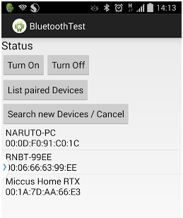
|
Implementation
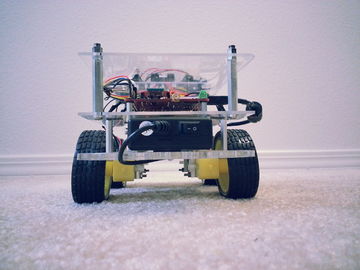
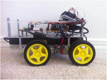
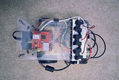
Actual Implementation Images:
Application Screenshots:
LED Conventions:
|
When 1st and 4th LED are blinking, it indicates that object is in range, i.e. Zone2 and FSM state is VD_STOP. |
|
|
When 2nd and 3rd LED glows continuously, it indicates that object has moved forward, i.e. in Zone3/Zone4 and FSM state is VD_FWD. |
|
|
When 1st and 4th LED glows continuously, it indicates that object is coming closer, i.e. in Zone1 and FSM state is VD_REV. |
|
|
When 1st and 4th LED blinks, it indicates that object is taking turn, and robot is trying to figure out where the object has turned and FSM state is VD_TURN. If robot is not able to find out turned object, it means that object has moved out of range. |
|
|
When 1st and 2nd LED glows continuously, it indicates that object is turning to left and FSM state is VD_FWD_LEFT. |
|
|
When 3rd and 4th LED glows continuously, it indicates that object is turning to right and FSM state is VD_FWD_RIGHT. |
|
|
When only 1st LED glows continuously, it indicates that object is turning to left but in backward direction and FSM state is VD_REV_LEFT. |
|
|
When only 4th LED glows continuously, it indicates that object is turning to right but in backward direction and FSM state is VD_REV_RIGHT. |
|
|
When all LEDs blink fast, it indicates that some obstacle has detected and FSM state is VD_ALARM. |
Testing & Technical Challenges
Normalization Algorithm:
Values retrieved from sensor are not stable. So we required to develop an algorithm that will give stable values from sensor. It should also remove spikes. We experimented a lot with this regard and finally developed an algorithm that gives fairly stable value of sensor without hampering the performance. Following graphs shows the Experiment results:

Above graph shows experimental results of actual sensor values, when object is moved from right to left. It is clearly visible in the graph that values are not stable and also has many spikes.

Above graph shows experimental results of mean/average of past 30 values of sensor. These values are fairly stable, but it does not help to detect object if object moves very fast.

Above graph shows experimental results of median of past 30 values. These are the most stable value that we could find out. So we used median to calculate sensor values, and used these values in our algorithm.
Motor Selection:
Stepper Motor:
Initially we plan to use the Stepper motor with our DC motor so that we can control the position of our robot very precisely. As the servo motor that we plan to use is very heavy due to which our chassis weight get increased to a extreme level, and there is torque degradation at higher speed in stepper motor which is not desirable for our project so we plan to drop the use of stepper motor.
Servo Motor:
Initially we plan to use the Servo motor instead of DC motor for our project so that we can provide a high torque to our robot wheels, but due to some disadvantage of servo motor like it continue to draw a high current when it is stuck at particular position make it undesirable for our project.
DC Motor:
Finally we select the DC motor instead of using Stepper motor and Servo Motor. There are some advantages of DC motor like they can run at very high RPM value, provide full rotation , continue to rotate until power is removed, can be easily controlled using PWM. This advantage of DC motor matches with the requirement of the motor that we are looking for our project.
Sensor Selection:
Nordic Wi-Fi:
Initially we plan to use Nordic Wi-Fi present on our SJ One board to calculate the distance between robot and the object so that accordingly we can change the position of the robot. When we perform the experiment between two Nordic Wi-Fi and tried calculating the distance between them the outcome result were not favorable, we were getting negligible change in the value when we change the position of one Wi-Fi module with respect to other. The outcome results were not desirable for our project so we drop the idea of using the Wi-Fi module.
Ultrasonic Sensor:
After getting the undesirable result from Wi-Fi we plan to use ultrasonic sensor to calculate the distance between the object and robot. When we perform the experiment the outcome result were not favorable, though the range of ultrasonic sensor was too good but the beam angle it generates to detect the object which come under its range was too high due to which it was able to detect a large number of object, so we were not able to calculate the exact distance between the original object and the robot. So we plan to drop the idea of using Ultrasonic Sensor.
Proximity Sensor:
We than plan to use the proximity sensor to calculate the distance between the object and robot. The proximity sensor we used to perform the experiment has a range of 20 cm to 150 cm, the outcome result from the experiment were favorable. We were able to calculate the exact distance between the robot and the object. So we decide to use the proximity sensor for our project to calculate the distance between robot and object.
Motor Calibration Issue:
As we decided to use DC motor for our project by performing a number of experiments, we plan to use 4 DC motor one for each wheel of the robot. After connecting DC motor to the wheels of the robot we check the alignment of all the four wheels, if they were not alignment we make all of them align by performing a number of hit and trial methods. The next issue is to run each motor at different speed at the same input given voltage so that we can control and move our robot in any direction. All the four motor speed is control individually by calculating the separate PWM value for each motor.
Sensor Calibration Issue:
As we decide to use proximity sensor for our project we have to solve a number of calibration issue related with this sensor. The first thing is we have to decide the number of sensor required for our project. We decided to begin our experiment using three sensors, the next thing we have to decide is the position where we can place these sensor on our robot. After performing a lot of experiment we found that if our target object comes in a range less than 20cm from our robot all the sensor start throwing some garbage value. So we decided to place the sensor at the back of robot with their face facing front so that the sensor will not through garbage values if the target object is very close to the robot. Now we have to decide the angle at which our sensor must be placed so that it can detect the target object anywhere between the angles of 0 to 180 degree. So after performing a number of experiments we place our three sensors at 45, 90 and 135 degree. After placing the sensor at the proper position the next thing we have to determine is the distance between the object and the robot. For this we use the normalization method on the sensor value so that we can predict the correct distance between the object and the robot.
Android Application Issue:
Operations involving the UI have the high Priority in the Android. Because of this, Updating the text Box with the sensor values and the direction will throw an IOexception. Because of this the application crashes.
Solution: Let the thread involving the receive function be executing as the background process and the UI update shall happen only after the execution of the receiving function.
Establishing the initial pairing between the devices caused some faults such as socket was not open or already read.
Solution: This was due to the sudden termination of the previous socket connection. The Socket has to be closed on Application exit, on all the catch exceptions and any sudden termination.
Conclusion
The Virtual Dog was a very challenging and research oriented project. Detailed analysis were made on various sensors while trying to implement the project. The project was built on a small scale. This would work as a prototype to build the applications such as shopping cart following a person in crowded areas such as the grocery stores etc.
Project Video
Project Source Code
References
Acknowledgement
The hardware components were made available from Amazon, Sparkfun, Adafruit. Thanks to Preetpal Kang for providing right guidance for our project.
References Used
LPC_USER_MANUAL
RN-42 Data Sheet
Socialledge Embedded Systems Wiki
L293D Data Sheet
IR Sensor Data Sheet
