Difference between revisions of "S24: Team Gran Turismo"
(→Team Members & Responsibilities) |
|||
| (152 intermediate revisions by the same user not shown) | |||
| Line 1: | Line 1: | ||
| − | == | + | [[File:2023 GranTurismo Logo.png|right|800 px]] |
| − | < | + | |
| − | + | === === | |
| + | |||
| + | == <span style="color:blue; font-family:Linux Libertine; font-size:300%">Gran</span> <span style="color:red; font-family:Linux Libertine; font-size:300%">Turismo</span> == | ||
| + | |||
| + | |||
| + | {| | ||
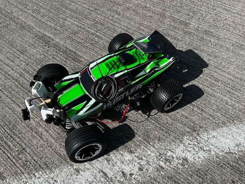
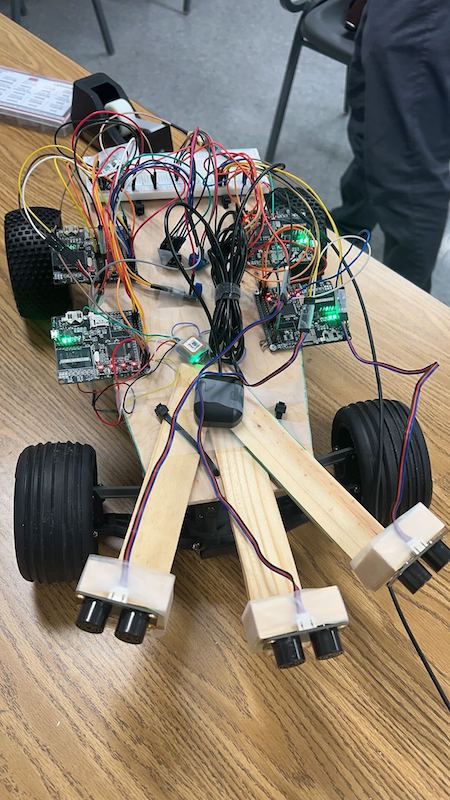
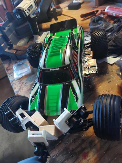
| + | |[[File:IMG 4302.jpg|thumb|left|500px|GT Final Packaging]] | ||
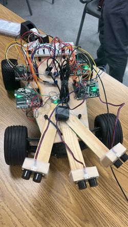
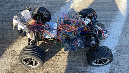
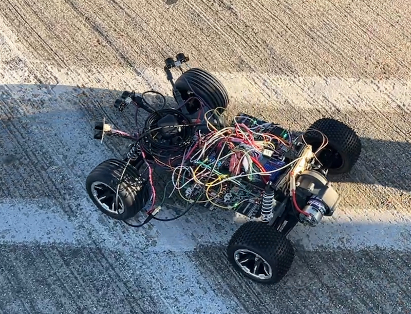
| + | |[[File:2024 GT Rough Proto.jpg|thumb|center|250px|GT Prototype 1]] | ||
| + | |[[File:2024 GT Prototype.jpg|thumb|center|500px|GT Prototype 2]] | ||
| + | |} | ||
| − | == Abstract == | + | === Abstract === |
"The Gran Turismo" is an autonomous RC car designed to navigate to a specified destination using GPS coordinates, communicated via a mobile application. The car integrates four microcontrollers (Driver, Sensor/Bridge, Geo, and Motor nodes) which communicate over a Controller Area Network (CAN) bus. It utilizes FreeRTOS to manage periodic tasks for data gathering, processing, and decision-making, ensuring effective obstacle detection and avoidance while maintaining the intended path. | "The Gran Turismo" is an autonomous RC car designed to navigate to a specified destination using GPS coordinates, communicated via a mobile application. The car integrates four microcontrollers (Driver, Sensor/Bridge, Geo, and Motor nodes) which communicate over a Controller Area Network (CAN) bus. It utilizes FreeRTOS to manage periodic tasks for data gathering, processing, and decision-making, ensuring effective obstacle detection and avoidance while maintaining the intended path. | ||
=== Introduction === | === Introduction === | ||
| − | The project was divided into 5 | + | The project was divided into 5 nodes: |
| − | * Sensor/Bridge node | + | * [https://gitlab.com/lianshi.gan/sjtwo-c-team-gran-turismo/-/tree/GT_Sensor?ref_type=heads Sensor / Bridge node] |
| − | * Motor node | + | * [https://gitlab.com/lianshi.gan/sjtwo-c-team-gran-turismo/-/tree/GT_Motor?ref_type=heads Motor node] |
| − | * Geo node | + | * [https://gitlab.com/lianshi.gan/sjtwo-c-team-gran-turismo/-/tree/GT_Geo?ref_type=heads Geo node] |
| − | * Driver node | + | * [https://gitlab.com/lianshi.gan/sjtwo-c-team-gran-turismo/-/tree/GT_Driver_V2?ref_type=heads Driver / LCD node] |
| − | * | + | * Mobile Application |
=== Team Members & Responsibilities === | === Team Members & Responsibilities === | ||
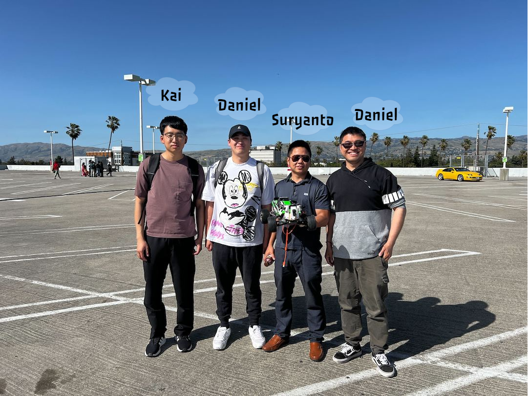
| − | + | [[File:2024 GT Team.png]] | |
| − | Team Members: | + | <span style="font-size:100%;">'''Team Members (From Left to Right):'''</span> |
<BR/> | <BR/> | ||
| − | Daniel Zhao Yeung <BR/> | + | * Kaijian Wu <BR/> |
| − | Suryanto Phienanda <BR/> | + | * Daniel Zhao Yeung <BR/> |
| − | + | * Suryanto Phienanda <BR/> | |
| − | Lianshi Gan <BR/> | + | * Lianshi Gan <BR/> |
| Line 43: | Line 52: | ||
! scope="row" style="text-align: left;"| | ! scope="row" style="text-align: left;"| | ||
* [https://www.linkedin.com/in/lianshi-gan-967494116/ Lianshi Gan] | * [https://www.linkedin.com/in/lianshi-gan-967494116/ Lianshi Gan] | ||
| + | [[File: Lianshi Gan.jpg|200px]] | ||
| | | | ||
| − | * Sensor | + | * Sensor Node |
| + | * Testing | ||
| + | * RC Car Assembly Assistant | ||
|- | |- | ||
! scope="row" style="text-align: left;"| | ! scope="row" style="text-align: left;"| | ||
| + | |||
* Suryanto Phienanda | * Suryanto Phienanda | ||
| − | + | [[File: Suryanto Phienanda.jpg|200px]] | |
| | | | ||
| − | * Motor | + | * Motor Node |
| + | * LCD | ||
| + | * Driver Node | ||
| + | * RC Car Assembly | ||
|- | |- | ||
! scope="row" style="text-align: left;"| | ! scope="row" style="text-align: left;"| | ||
* Kaijian Wu | * Kaijian Wu | ||
| | | | ||
| − | * Mobile App | + | * Mobile App, Bridge Node |
|- | |- | ||
| Line 92: | Line 108: | ||
* Get all the sensors and parts. | * Get all the sensors and parts. | ||
* Play with sensors and SJ2 boards. | * Play with sensors and SJ2 boards. | ||
| − | | <font color = " | + | | <font color = "green">Completed |
|- | |- | ||
| Line 103: | Line 119: | ||
* Get Data from different modules(GPS, Sensors). | * Get Data from different modules(GPS, Sensors). | ||
* Starting to check on motor. | * Starting to check on motor. | ||
| − | | <font color = " | + | | <font color = "green">Completed |
|- | |- | ||
| Line 114: | Line 130: | ||
* Build libraries for all modules (Bluetooth/WIFI, GPS, Sensor....). | * Build libraries for all modules (Bluetooth/WIFI, GPS, Sensor....). | ||
* Continue work on mobile app. | * Continue work on mobile app. | ||
| − | | <font color = " | + | | <font color = "green">Completed |
|- | |- | ||
| Line 125: | Line 141: | ||
* Create unit/integration tests. | * Create unit/integration tests. | ||
* Continue work on mobile app. | * Continue work on mobile app. | ||
| − | | <font color = " | + | | <font color = "green">Completed |
|- | |- | ||
| Line 135: | Line 151: | ||
* Motors with PID control. | * Motors with PID control. | ||
* Continue work on mobile app. | * Continue work on mobile app. | ||
| − | | <font color = " | + | | <font color = "green">Completed |
|- | |- | ||
| Line 145: | Line 161: | ||
* Integrate bluetooth module | * Integrate bluetooth module | ||
* Continue with mobile app | * Continue with mobile app | ||
| − | | <font color = " | + | | <font color = "green">Completed |
|- | |- | ||
| Line 154: | Line 170: | ||
* Finalize/Connect mobile app with RC car. | * Finalize/Connect mobile app with RC car. | ||
* Obstacle avoidance. | * Obstacle avoidance. | ||
| − | | <font color = " | + | | <font color = "green">Completed |
|- | |- | ||
| Line 163: | Line 179: | ||
* PROTOTYPE 3 | * PROTOTYPE 3 | ||
* Prepare for outdoor tests. | * Prepare for outdoor tests. | ||
| − | | <font color = " | + | | <font color = "green">Completed |
|- | |- | ||
| Line 172: | Line 188: | ||
* PROTOTYPE 4 | * PROTOTYPE 4 | ||
* Perform outdoors tests and recalibrate. | * Perform outdoors tests and recalibrate. | ||
| − | | <font color = " | + | | <font color = "green">Completed |
|- | |- | ||
| Line 180: | Line 196: | ||
| | | | ||
* Final Demo | * Final Demo | ||
| − | | <font color = " | + | | <font color = "green">Completed |
|} | |} | ||
<HR> | <HR> | ||
| − | + | ||
| + | === Prototype 1 === | ||
| + | |||
| + | [[File:IMG 2631.jpg]] | ||
| + | |||
| + | === Prototype 2 === | ||
| + | [[File:IMG 4345.jpg]] | ||
== Parts List & Cost == | == Parts List & Cost == | ||
| Line 205: | Line 227: | ||
| CAN Transceivers MCP2551-I/P | | CAN Transceivers MCP2551-I/P | ||
| Microchip [http://www.microchip.com/wwwproducts/en/en010405] | | Microchip [http://www.microchip.com/wwwproducts/en/en010405] | ||
| − | | | + | | 4 |
| Free Samples | | Free Samples | ||
| + | |- | ||
| + | ! scope="row"| 3 | ||
| + | | Ultrasonic Sensor URM09 from DFRobots | ||
| + | | dfrobot [https://www.dfrobot.com/product-1862.html] | ||
| + | | 3 | ||
| + | | $8.00 * 3 | ||
| + | |- | ||
| + | ! scope="row"| 4 | ||
| + | | DSD TECH HM-10 Bluetooth 4.0 BLE | ||
| + | | Amazon [https://www.amazon.com/dp/B06WGZB2N4?psc=1&ref=ppx_yo2ov_dt_b_product_details] | ||
| + | | 1 | ||
| + | | $12.00 | ||
| + | |- | ||
| + | ! scope="row"| 5 | ||
| + | | Tilt Compensated Magnetic Compass (CMPS14) | ||
| + | | RobotShop [https://www.robotshop.com/products/tilt-compensated-magnetic-compass-cmps14] | ||
| + | | 1 | ||
| + | | $41.00 | ||
| + | |- | ||
| + | ! scope="row"| 6 | ||
| + | | GT-U7 GPS Module GPS Receiver | ||
| + | | Amazon [https://www.amazon.com/Navigation-Satellite-Compatible-Microcontroller-Geekstory/dp/B07PRGBLX7?th=1] | ||
| + | | 1 | ||
| + | | $15.00 | ||
| + | |- | ||
| + | ! scope="row"| 7 | ||
| + | | Bingfu Waterproof Active GPS Navigation Antenna | ||
| + | | Amazon [https://www.amazon.com/gp/product/B083D59N55/ref=ppx_yo_dt_b_search_asin_title?ie=UTF8&th=1] | ||
| + | | 1 | ||
| + | | $41.00 | ||
| + | |- | ||
| + | ! scope="row"| 8 | ||
| + | | LM393 Wheel Encoder | ||
| + | | Amazon [https://www.amazon.com/dp/B0CP8YSKLP/ref=sspa_dk_detail_2?psc=1&pd_rd_i=B0CP8YSKLP&pd_rd_w=mQZWm&content-id=amzn1.sym.f734d1a2-0bf9-4a26-ad34-2e1b969a5a75&pf_rd_p=f734d1a2-0bf9-4a26-ad34-2e1b969a5a75&pf_rd_r=3VEEWWSBPY86MBM444DH&pd_rd_wg=D2B7q&pd_rd_r=e274dcb0-f9cb-4b6b-b9e1-b349a1e8a382&s=industrial&sp_csd=d2lkZ2V0TmFtZT1zcF9kZXRhaWw] | ||
| + | | 1 | ||
| + | | $8.49 | ||
| + | |- | ||
| + | ! scope="row"| 8 | ||
| + | | ILI9486 TFT LCD | ||
| + | | Amazon [https://www.amazon.com/480x320-Screen-Module-Arduino-Without/dp/B07NWH47PV/ref=sr_1_1?crid=MIRPWDOKBRDC&dib=eyJ2IjoiMSJ9.xp4UM9lbmLqcJKtrUc_mT0j7LSNtNBGYXE9kQKb52r3ttDuQ6PW15RQkGjxsUBQCXXZkTSRem-MhRjj9RG6sxA.Cpp3U15prQ69dl286ilYa2Gz7BEW_6dmdoVzbFESKrY&dib_tag=se&keywords=ftvogue+lcdf&qid=1716609521&sprefix=ftvogue+lc%2Caps%2C143&sr=8-1] | ||
| + | | 1 | ||
| + | | $17.29 | ||
| + | |- | ||
| + | ! scope="row"| 9 | ||
| + | | LED Headlights | ||
| + | | Amazon [https://www.amazon.com/ShareGoo-Headlights-Taillight-Accessories-Traxxas/dp/B073XRDPNR/ref=pd_ci_mcx_mh_mcx_views_0?pd_rd_w=sPs0I&content-id=amzn1.sym.8b590b55-908d-4829-9f90-4c8752768e8b%3Aamzn1.symc.40e6a10e-cbc4-4fa5-81e3-4435ff64d03b&pf_rd_p=8b590b55-908d-4829-9f90-4c8752768e8b&pf_rd_r=HJTKB4GNQWKHNW3RHY42&pd_rd_wg=bvKym&pd_rd_r=0643728e-24a6-4e2a-8316-86106b8df3ad&pd_rd_i=B073XRDPNR] | ||
| + | | 1 | ||
| + | | $7.95 | ||
|- | |- | ||
|} | |} | ||
| Line 212: | Line 282: | ||
<HR> | <HR> | ||
<BR/> | <BR/> | ||
| − | |||
| − | |||
| − | |||
| − | |||
| − | |||
== CAN Communication == | == CAN Communication == | ||
| − | |||
=== Hardware Design === | === Hardware Design === | ||
| − | + | ||
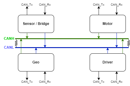
| + | [[File: 2024 GT CAN Line.png|thumb|center|800px|CAN Communication Line]] | ||
| + | |||
| + | Each Node is connected to a CAN transceiver where CAN receiver (RX) on SJ2 is connected to CAN Transceiver receiver (RX) and CAN transmitter (TX) on SJ2 is connected to CAN Transceiver transmitter (TX). | ||
| + | The CAN transceivers are then connected to each other through CANH and CANL lines that are connected to 120Ω terminating resistors to ensure the integrity of the signals on CANH and CANL lines. | ||
=== DBC File === | === DBC File === | ||
| − | + | [https://gitlab.com/lianshi.gan/sjtwo-c-team-gran-turismo/-/blob/GT_infrastructure/dbc/project.dbc?ref_type=heads DBC file] | |
| − | < | + | |
| + | <pre> | ||
| + | BO_ 100 DRIVER_CMD: 3 DRIVER | ||
| + | SG_ DRIVER_CMD_heartbeat : 0|1@1+ (1,0) [0|0] "" SENSOR,MOTOR | ||
| + | SG_ DRIVER_CMD_steer : 1|4@1+ (1,-5) [-5|5] "degrees" MOTOR | ||
| + | SG_ MOTOR_CMD_drive : 5|4@1+ (1,-2) [-2|5] "kph" MOTOR | ||
| + | |||
| + | BO_ 105 GPS_CURRENT_COORD : 8 GPS | ||
| + | SG_ GPS_CURRENT_COORD_lat_degree : 0|8@1- (1,-90) [-90|90] "degrees" BRIDGE | ||
| + | SG_ GPS_CURRENT_COORD_lat_minutes : 8|6@1+ (1,0) [0|60] "minutes" BRIDGE | ||
| + | SG_ GPS_CURRENT_COORD_lat_seconds : 14|16@1+ (0.001,0) [0|60] "seconds" BRIDGE | ||
| + | SG_ GPS_CURRENT_COORD_long_degree : 30|9@1- (1,-180) [-180|180] "degrees" BRIDGE | ||
| + | SG_ GPS_CURRENT_COORD_long_minutes : 39|6@1+ (1,0) [0|60] "minutes" BRIDGE | ||
| + | SG_ GPS_CURRENT_COORD_long_seconds : 45|16@1+ (0.001,0) [0|60] "seconds" BRIDGE | ||
| + | BO_ 110 GPS_DESTINATION_LOCATION: 8 BRIDGE | ||
| + | SG_ GPS_DESTINATION_LOCATION_lat_degree : 0|8@1- (1,-90) [-90|90] "degrees" GPS | ||
| + | SG_ GPS_DESTINATION_LOCATION_lat_minutes : 8|6@1+ (1,0) [0|60] "minutes" GPS | ||
| + | SG_ GPS_DESTINATION_LOCATION_lat_seconds : 14|16@1+ (0.001,0) [0|60] "seconds" GPS | ||
| + | SG_ GPS_DESTINATION_LOCATION_long_degree : 30|9@1- (1,-180) [-180|180] "degrees" GPS | ||
| + | SG_ GPS_DESTINATION_LOCATION_long_minutes : 39|6@1+ (1,0) [0|60] "minutes" GPS | ||
| + | SG_ GPS_DESTINATION_LOCATION_long_seconds : 45|16@1+ (0.001,0) [0|60] "seconds" GPS | ||
| + | BO_ 120 COMPASS_CURRENT: 7 COMPASS | ||
| + | SG_ COMPASS_CURRENT_heading : 0|12@1+ (1,0) [0|359.9] "degrees" DRIVER | ||
| + | SG_ COMPASS_CURRENT_bearing : 12|12@1+ (1,0) [0|359.9] "degrees" DRIVER | ||
| + | SG_ COMPASS_CURRENT_distance_to_dest : 24|32@1+ (0.1,0) [0|0] "meters" DRIVER | ||
| + | |||
| + | BO_ 200 SENSOR_SONARS: 8 SENSOR | ||
| + | SG_ SENSOR_SONARS_front_left : 0|13@1+ (0.1,0) [0|520] "cm" DRIVER | ||
| + | SG_ SENSOR_SONARS_front_right : 13|13@1+ (0.1,0) [0|520] "cm" DRIVER | ||
| + | SG_ SENSOR_SONARS_front_middle : 26|13@1+ (0.1,0) [0|520] "cm" DRIVER | ||
| + | SG_ SENSOR_SONARS_rear : 39|13@1+ (0.1,0) [0|520] "cm" DRIVER | ||
| + | |||
| + | BO_ 300 MOTOR_CMD: 2 MOTOR | ||
| + | SG_ MOTOR_CMD_speed_kph : 0|8@1+ (1,0) [0|35] "kph" DRIVER | ||
| + | SG_ MOTOR_CMD_angle : 8|8@1+ (1,0) [-5|5] "degrees" DRIVER | ||
| + | |||
| + | </pre> | ||
<HR> | <HR> | ||
<BR/> | <BR/> | ||
| − | == Sensor ECU == | + | |
| − | + | == Sensor and Bridge ECU == | |
| + | [https://gitlab.com/lianshi.gan/sjtwo-c-team-gran-turismo/-/merge_requests/2 Sensor Gitlab] | ||
=== Hardware Design === | === Hardware Design === | ||
| + | [[File:20240516 173629.jpg]] | ||
| + | |||
| + | <HR> | ||
| + | Connection Diagram | ||
| + | [[File:sensor hw.png]] | ||
| + | |||
| + | ==== Ultrasonic Sensor ==== | ||
| + | |||
| + | [[File:MFG SEN0388.jpeg|200px]] | ||
| + | |||
| + | Selecting the appropriate distance sensor is crucial for the success of the project. Our team chose the Ultrasonic Sensor URM09 from DFRobots due to its ease of use and cost-effectiveness. The URM09 offers multiple communication protocols, and we opted for the I2C package to simplify the configuration and reading process, allowing us to focus on the overall system integration. | ||
| + | |||
| + | * Ultra-Sonic Sensor URM09 (I2C Protocol) | ||
| + | ** '''Supply Voltage:''' 3.3~5.5V DC | ||
| + | ** '''Operating Current:''' 20mA | ||
| + | ** '''Operating Temperature Range:''' -10℃~+70℃ | ||
| + | ** '''Measurement Range:''' 2cm~500cm (can be set) | ||
| + | ** '''Resolution:''' 1cm | ||
| + | ** '''Accuracy:''' 1% | ||
| + | ** '''Frequency:''' 50Hz Max | ||
| + | ** '''Dimension:''' 47mm × 22 mm/1.85” × 0.87” | ||
| + | |||
| + | ==== Bluetooth Module ==== | ||
| + | For the communication between the Mobile app and the RC car. We use the DSD TECH HM-10 Bluetooth 4.0 BLE module. This module communicate with the SJ2 board by using UART. It transmits raw data between mobile app and bridge. It is lightweight and has small size. | ||
| + | |||
| + | [[File:DSD TECH HM-10 Bluetooth 4.0 BLE.jpg|200px]] | ||
| + | |||
| + | |||
| + | * DSD TECH HM-10 Bluetooth 4.0 BLE | ||
| + | ** '''Operating voltage:''' 3.3V | ||
| + | ** '''Core module:''' MH-10 | ||
| + | ** '''Support device:''' iOS device(iphone and ipad). But does not support the version is lower than the android 4.3 phone(it don't support classic bluetooth 2.0 spp features) | ||
=== Software Design === | === Software Design === | ||
| − | < | + | Preiocally tasks |
| + | * receiving data | ||
| + | ** Current coordinate from Geo ECU (Geo node) | ||
| + | ** Destination coordinates, command data from Mobile App (App) | ||
| + | ** Sensor data from sensor (Ultrasonic Sensor URM09) | ||
| + | * sending data: | ||
| + | ** Destination coordinates, sensor data to Driver ECU (Driver node) | ||
| + | ** Sensor data to app (App) | ||
| + | |||
| + | |||
| + | <pre> | ||
| + | void periodic_callbacks__1Hz(uint32_t callback_count) { | ||
| + | if (can__is_bus_off(can1)) { | ||
| + | can__reset_bus(can1); | ||
| + | gpio__toggle(board_io__get_led0()); | ||
| + | } | ||
| + | can_bus_handler__receive_current_gps(); | ||
| + | can_bus_handler_service_mia_1Hz(); | ||
| + | const dbc_GPS_CURRENT_COORD_s current_coord = can_bus_handler__get_received_current_gps(); | ||
| + | |||
| + | bluetooth__send_current_gps_to_app(current_coord); | ||
| + | bluetooth__send_sensor_data_to_app(); | ||
| + | } | ||
| + | |||
| + | void periodic_callbacks__10Hz(uint32_t callback_count) { | ||
| + | bluetooth__receive_all_data_from_app(); | ||
| + | |||
| + | can_bus_handler__transmit_sensors(); | ||
| + | can_bus_handler__transmit_command(); | ||
| + | can_bus_handler__transmit_destination_gps(); | ||
| + | } | ||
| + | </pre> | ||
| + | |||
=== Technical Challenges === | === Technical Challenges === | ||
| − | < | + | ==== Bluetooth Module ==== |
| + | *''' Challenge:''' : Due to its design, it can read/send a string up to 20 characters at a time. Any string more than 20 characters will be break into 2 lines automatically and process. The datasheet provides limited information when developing the Bluetooth module. | ||
| + | *''' Solution:''' On SJ2 board side, we break out data into serval strings and pad '0' into some data string to ensure it is send in exact 20 characters. | ||
| + | |||
| + | ==== Sensor Module ==== | ||
| + | ===== Transmitting Sensor Data ===== | ||
| + | Since there are some "printf" were set up for debugging sensor data, we transmitting data on 5Hz in order to avoid crashing the SJ2 board. It wasn't any issue when we doing unit testing and obstacle avoiding testing run. However, the low 5 Hz cause turning delay when we actually run the RC car in high speed. Remember to ensure sensor data transmitting at least 10 to 20 Hz. | ||
| + | |||
| + | <pre> | ||
| + | void periodic_callbacks__10Hz(uint32_t callback_count) { | ||
| + | bluetooth__receive_all_data_from_app(); | ||
| + | |||
| + | |||
| + | can_bus_handler__transmit_sensors(); | ||
| + | |||
| + | can_bus_handler__transmit_command(); | ||
| + | can_bus_handler__transmit_destination_gps(); | ||
| + | } | ||
| + | </pre> | ||
| + | |||
| + | ===== Configure 4 ADC channels ===== | ||
| + | We load the distance sensor data by ADC channel. | ||
| + | There are only 3 channels ready to use on SJ2 board. | ||
| + | Need to modify P0_26 as below to unlock ADC: | ||
| + | |||
| + | <pre> | ||
| + | static void distance__configure_all_adc_pins(void) { | ||
| + | LPC_IOCON->P0_25 &= ~(3 << 3); | ||
| + | LPC_IOCON->P0_25 &= ~(1 << 7); | ||
| + | |||
| + | LPC_IOCON->P0_26 &= ~(3 << 3); | ||
| + | LPC_IOCON->P0_26 &= ~(1 << 16); | ||
| + | LPC_IOCON->P0_26 &= ~(1 << 7); | ||
| + | |||
| + | LPC_IOCON->P1_30 &= ~(3 << 3); | ||
| + | LPC_IOCON->P1_30 &= ~(1 << 7); | ||
| + | |||
| + | LPC_IOCON->P1_31 &= ~(3 << 3); | ||
| + | LPC_IOCON->P1_31 &= ~(1 << 7); | ||
| + | } | ||
| + | </pre> | ||
<HR> | <HR> | ||
<BR/> | <BR/> | ||
| + | |||
== Motor ECU == | == Motor ECU == | ||
| − | + | [https://gitlab.com/lianshi.gan/sjtwo-c-team-gran-turismo/-/tree/GT_Motor?ref_type=heads Motor GitLab] | |
| + | |||
| + | {| | ||
| + | |[[File: 2024 GT Battery.jpg|thumb|left|text-top|300px|Traxxas 7.2V NiMH Battery]] | ||
| + | |[[File: 2024 GT RC Rustler.jpg|thumb|middle|text-top|400px|Traxxas RC Rustler]] | ||
| + | |[[File: 2024 GT RC ESC DC.jpg|thumb|middle|text-top|300px|Traxxas ESC & DC Motor]] | ||
| + | |[[File: 2024 GT Servo.jpg|thumb|middle|text-top|400px|Traxxas Servo Motor]] | ||
| + | |} | ||
=== Hardware Design === | === Hardware Design === | ||
| + | |||
| + | {| | ||
| + | |[[File: 2024 GT Motor Layout.png|thumb|left|text-top|1000px|Motor Node Layout]] | ||
| + | |} | ||
| + | |||
| + | Traxxas RC car is controlled using a built-in ESC provided by Traxxas. Since there is not a single documentation on how Traxxas ESC works, it needed to be decoded manually to understand how the ESC works. | ||
| + | |||
| + | Based on the observation, it seems that Traxxas ESC must be initialized with neutral PWM signal, which is indicated by a red LED on ESC. This is only applicable to the DC motor. | ||
| + | |||
| + | With the initialized PWM frequency of 100Hz, it was observed that PWM signal of 16.0f is the neutral signal for DC motor while PWM signal of 14.0f is the neutral signal for servo motor. | ||
| + | |||
| + | |||
| + | Both DC and servo motor were powered by 7.2V NiMH battery from Traxxas. | ||
| + | |||
| + | |||
| + | To control the speed of the RC car, an RPM sensor with a wheel encoder were needed to keep track of the current speed of the car. | ||
| + | |||
| + | A PID controller was implemented so that the DC motor could be incremented properly without any visible overshoot. | ||
| + | |||
| + | Since the RC car is also capable of reversing, the PID controller must also be capable of reversing properly. However, to reverse, the ESC must first be set to neutral before decreasing the PWM. | ||
| + | |||
| + | To avoid any damage on the DC motor, the ESC was given 1-second to be neutral before reversing. | ||
| + | |||
| + | |||
| + | <span style>'''Details on how Traxxas XL-5 ESC functions (DC Motor):'''</span> | ||
| + | * PWM 16.0 -- Neutral | ||
| + | * PWM < 16.0 -- Reverse | ||
| + | * PWM > 16.0 -- Forward | ||
| + | |||
| + | <span style>'''Details on how Servo Motor functions:'''</span> | ||
| + | * PWM 14.0 -- Neutral | ||
| + | * PWM < 14.0 -- Left | ||
| + | * PWM > 14.0 -- Right | ||
| + | |||
=== Software Design === | === Software Design === | ||
| − | < | + | |
| + | In Motor node, two periodic callbacks were utilized (1 Hz and 10 Hz). | ||
| + | |||
| + | <span style>'''1 Hz Periodic Callback''':</span> | ||
| + | |||
| + | 1. Checking for photoresistor value (mounted on the windshield of the car) | ||
| + | |||
| + | <pre> | ||
| + | headlight.c | ||
| + | |||
| + | void headlight__toggle(void) { | ||
| + | if (photoresistor__get_reading(ADC__CHANNEL_4) > 1500) { | ||
| + | headlight__on(); | ||
| + | } else { | ||
| + | headlight__off(); | ||
| + | } | ||
| + | } | ||
| + | </pre> | ||
| + | |||
| + | 2. Checking for CAN bus status | ||
| + | |||
| + | <pre> | ||
| + | if (can__is_bus_off(can1)) { | ||
| + | can__reset_bus(can1); | ||
| + | } | ||
| + | </pre> | ||
| + | |||
| + | |||
| + | <span style>'''10 Hz Periodic Callback''':</span> | ||
| + | |||
| + | 1. Receive all messages from CAN transceiver | ||
| + | |||
| + | <pre> | ||
| + | can_bus_handler.c | ||
| + | |||
| + | void can_bus_handler__receive_all_messages(void) { | ||
| + | can__msg_t can_msg = {0}; | ||
| + | dbc_DRIVER_CMD_s new_driver_cmd = {0}; | ||
| + | |||
| + | while (can__rx(can1, &can_msg, 0)) { | ||
| + | dbc_message_header_t header = {.message_dlc = can_msg.frame_fields.data_len, .message_id = can_msg.msg_id}; | ||
| + | |||
| + | if (dbc_decode_DRIVER_CMD(&new_driver_cmd, header, can_msg.data.bytes)) { | ||
| + | motor__receive_driver_message(new_driver_cmd); | ||
| + | } | ||
| + | } | ||
| + | } | ||
| + | </pre> | ||
| + | |||
| + | 2. Transmit messages to CAN transceiver | ||
| + | |||
| + | <pre> | ||
| + | can_bus_handler.c | ||
| + | |||
| + | void can_bus_handler__transmit_messages(void) { | ||
| + | dbc_MOTOR_CMD_s current_motor_cmd = motor__get_current_motor_cmd(); | ||
| + | |||
| + | dbc_encode_and_send_MOTOR_CMD(NULL, ¤t_motor_cmd); | ||
| + | } | ||
| + | </pre> | ||
| + | |||
| + | 3. Adjust duty cycle to reach the desired speed | ||
| + | |||
| + | <pre> | ||
| + | motor.c | ||
| + | |||
| + | void motor__pid(void) { | ||
| + | rc_car_current_speed = rpm_sensor__get_current_speed_kph(); | ||
| + | |||
| + | float error = rc_car_target_speed - rc_car_current_speed; | ||
| + | |||
| + | if ((int)error != 0) { | ||
| + | motor__pid_update_p_term(error); | ||
| + | motor__pid_update_i_term(error); | ||
| + | motor__pid_update_d_term(error); | ||
| + | |||
| + | motor__pid_update_pwm_duty_cycle(PID_P_TERM, PID_I_TERM, PID_D_TERM); | ||
| + | } | ||
| + | |||
| + | motor__set_dc_motor_speed(rc_car_duty_cycle); | ||
| + | } | ||
| + | </pre> | ||
| + | |||
| + | where the P-term is as follow: | ||
| + | |||
| + | <pre> | ||
| + | ... | ||
| + | error = target_speed - current_speed; | ||
| + | ... | ||
| + | |||
| + | static void motor__pid_update_p_term(float error) { PID_P_TERM = PID_KP * error; } | ||
| + | </pre> | ||
| + | |||
| + | the I-term is as follow: | ||
| + | |||
| + | <pre> | ||
| + | static void motor__pid_update_i_term(float error) { | ||
| + | PID_I_TMP += error; | ||
| + | |||
| + | if (PID_I_TMP > PID_IMAX_ERROR) { | ||
| + | PID_I_TMP = PID_IMAX_ERROR; | ||
| + | } else if (PID_I_TMP < PID_IMIN_ERROR) { | ||
| + | PID_I_TMP = PID_IMIN_ERROR; | ||
| + | } | ||
| + | |||
| + | PID_I_TERM = PID_KI * PID_I_TMP; | ||
| + | } | ||
| + | </pre> | ||
| + | |||
| + | the D-term is as follow: | ||
| + | |||
| + | <pre> | ||
| + | static void motor__pid_update_d_term(float error) { | ||
| + | PID_D_TERM = PID_KD * (PID_D_TMP - error); | ||
| + | PID_D_TMP = error; | ||
| + | } | ||
| + | </pre> | ||
| + | |||
| + | then, the duty cycle is updated as follow: | ||
| + | |||
| + | <pre> | ||
| + | static void motor__pid_update_pwm_duty_cycle(float pterm, float iterm, float dterm) { | ||
| + | if (current_driver_cmd.DRIVER_CMD_drive < 0) { | ||
| + | rc_car_duty_cycle = DC_NEUTRAL_DUTY_CYCLE - (pterm + iterm + dterm); | ||
| + | } else { | ||
| + | rc_car_duty_cycle = DC_NEUTRAL_DUTY_CYCLE + (pterm + iterm + dterm); | ||
| + | } | ||
| + | } | ||
| + | </pre> | ||
| + | |||
=== Technical Challenges === | === Technical Challenges === | ||
| − | + | * Decoding Traxxas ESC | |
| + | Since there is not a single documentation on Traxxas ESC, the ESC must be decoded manually. Another hack that could be done to help decoding is by connecting the white wire (signal wire) of DC and servo to a logic analyzer and read the data through a software. However, simply by spending around 30-mins, the ESC should be understood. | ||
| + | |||
| + | * Figuring out KP, KI and KD term | ||
| + | If the engineer is not familiar with PID, this will be challenging since not understanding how these terms affect PID controller could cause the car to simply overshoot and crash. To solve this problem, simply put the RC car on top of a box with the rear wheels floating, then configure PID and see how each term affects the speed of the car. It is extremely helpful to read an [https://coder-tronics.com/pid-tutorial-c-code-example-pt2/ article] about PID first. | ||
| + | |||
| + | * Setting up RPM sensor | ||
| + | This might be the most challenging part (especially if one is not used to tinkering with hardware). To read the RPM, I had three options at first: RPM sensor, Reed sensor or Hall effect sensor. The reason why RPM sensor was selected was because the other sensors rely on magnetic field. Since the placement for the sensor would be close to DC motor, there is a high possibility that the reading will be affected by the magnetic field from DC motor. With wheel encoder, the magnetic field will not have any effect on the reading. | ||
<HR> | <HR> | ||
<BR/> | <BR/> | ||
| + | |||
== Geographical Controller == | == Geographical Controller == | ||
| − | + | [https://gitlab.com/lianshi.gan/sjtwo-c-team-gran-turismo/-/merge_requests/4 Geo Gitlab] | |
=== Hardware Design === | === Hardware Design === | ||
| + | ====Tilt Compensated Magnetic Compass (CMPS14)==== | ||
| + | [[File:Cmps14.png|200px]] | ||
| + | * Features a 3-axis gyro and 3-axis magnetometer | ||
| + | * Offers equally impressive performance to the CMPS12 | ||
| + | * Allows the calibration to be stopped and instead rely on a static calibration profile | ||
| + | The CMPS14 Tilt Compensated Magnetic Compass is equipped with a three-axis magnetometer, gyroscope, and accelerometer. It uses the advanced BNO080 to run algorithms that correct for any errors caused by the PCB tilting. Additionally, the module offers the option to halt calibration and use a static calibration profile instead. | ||
| + | |||
| + | |||
| + | ====Bingfu Waterproof Active GPS Navigation Antenna==== | ||
| + | [[File:Bingfu_antenna.png|200px]] | ||
| + | |||
| + | * Antenna: Radio | ||
| + | * Brand: BINGFU | ||
| + | * Color with U.FL Cable | ||
| + | * Impedance: 50 Ohm | ||
| + | * Maximum Range: 3 Meters | ||
| + | |||
| + | The Bingfu Waterproof Active GPS Navigation Antenna is a durable, water-resistant antenna with an adhesive mount and an SMA male connection. It comes with a 6-inch coaxial cable that connects from U.FL IPX IPEX to an SMA female connector. This antenna is designed for use with GPS modules and receivers to enhance tracking capabilities. | ||
| + | |||
| + | |||
| + | ====GT-U7 GPS Module GPS Receiver==== | ||
| + | [[File:Gt-u7.png|200px]] | ||
| + | |||
| + | * Brand: Geekstory | ||
| + | * Map Type: Satellite | ||
| + | *Item Weight: 0.2 Ounces | ||
| + | |||
| + | The GT-U7 is a compact GPS module with low power usage and high sensitivity. It uses a 7th generation chip and is compatible with NEO-6M software. This module excels in difficult environments like urban canyons and dense forests, providing precise location tracking. It includes a USB interface for easy connection to a computer using a standard phone cable, and comes with an active antenna. | ||
=== Software Design === | === Software Design === | ||
| − | + | ||
| + | Periodic callbacks are scheduled at 10 Hz. | ||
| + | |||
| + | void periodic_callbacks__10Hz(uint32_t callback_count) { | ||
| + | can_bus_handler__handle_all_messages(); | ||
| + | can_bus_handler__transmit_gps(); | ||
| + | can_bus_handler__transmit_compass(); | ||
| + | } | ||
| + | |||
| + | |||
| + | Preiocally tasks | ||
| + | * receiving data | ||
| + | ** Heading from compass (cmps14) | ||
| + | ** Destination coordinates from Mobile App | ||
| + | ** Current coordinates from GPS receiver (gt-u7) | ||
| + | * sending data: | ||
| + | ** Current coordinates to mobile app | ||
| + | ** Distance and bearing (from calculation of current and destination coordinates) to driver controller | ||
| + | ** Heading (from cmps14) to driver controller | ||
=== Technical Challenges === | === Technical Challenges === | ||
| − | + | * Getting accurate data of compass | |
| + | ** Follow the calibration procedure in the CMPS14 user manual. | ||
| + | ** Avoid areas with excessive wiring or magnets nearby. | ||
| + | ** Use the LED on the SJ2 board to indicate the calibration level. | ||
| + | ** Only transfer data when the `readyBit` is greater than 0. | ||
<HR> | <HR> | ||
<BR/> | <BR/> | ||
| − | < | + | == TFT LCD == |
| − | < | + | [[File:IMG 4314.jpg]] |
| − | == | + | [[File:IMG 4309.jpg]] |
| − | < | + | [[File:IMG 4311.jpg]] |
| + | [[File:IMG 4312.jpg]] | ||
| + | |||
| + | === Software Design === | ||
| + | |||
| + | The TFT LCD is updated every 1Hz. This is because the SJ2 will crash in 10Hz due to the MCU incapable of meeting the deadline of 0.1 second. | ||
| + | |||
| + | An alternative to this will be by implementing a state machine where only one sensor value will be updated at every callback. | ||
| + | |||
| + | However, the downside of implementing an FSM is that the value of the sensor will be inaccurate by 0.1 second. | ||
| + | |||
| + | <span style>'''1Hz Periodic Callback'''</span> | ||
| + | |||
| + | <pre> | ||
| + | void draw_lcd__write_sensor_data(dbc_SENSOR_SONARS_s sensor_data_from_can) { | ||
| + | color_e sensor_front_status = WHITE; | ||
| + | color_e sensor_left_status = WHITE; | ||
| + | color_e sensor_right_status = WHITE; | ||
| + | |||
| + | if (sensor_data_from_can.SENSOR_SONARS_front_middle <= driver__get_front_threshold()) { | ||
| + | sensor_front_status = RED; | ||
| + | } | ||
| + | if (sensor_data_from_can.SENSOR_SONARS_front_left <= driver__get_left_threshold()) { | ||
| + | sensor_left_status = RED; | ||
| + | } | ||
| + | if (sensor_data_from_can.SENSOR_SONARS_front_right <= driver__get_right_threshold()) { | ||
| + | sensor_right_status = RED; | ||
| + | } | ||
| + | |||
| + | tft__draw_number(28, 47, 255, 274, ((int)sensor_data_from_can.SENSOR_SONARS_front_left / 100) % 10, | ||
| + | sensor_left_status); | ||
| + | tft__draw_number(52, 71, 255, 274, ((int)sensor_data_from_can.SENSOR_SONARS_front_left / 10 % 10), | ||
| + | sensor_left_status); | ||
| + | tft__draw_number(76, 95, 255, 274, ((int)sensor_data_from_can.SENSOR_SONARS_front_left % 10), sensor_left_status); | ||
| + | |||
| + | tft__draw_number(224, 243, 255, 274, ((int)sensor_data_from_can.SENSOR_SONARS_front_right / 100) % 10, | ||
| + | sensor_right_status); | ||
| + | tft__draw_number(248, 267, 255, 274, ((int)sensor_data_from_can.SENSOR_SONARS_front_right / 10 % 10), | ||
| + | sensor_right_status); | ||
| + | tft__draw_number(272, 291, 255, 274, ((int)sensor_data_from_can.SENSOR_SONARS_front_right % 10), sensor_right_status); | ||
| + | |||
| + | tft__draw_number(120, 139, 116, 135, ((int)sensor_data_from_can.SENSOR_SONARS_front_middle / 100) % 10, | ||
| + | sensor_front_status); | ||
| + | tft__draw_number(144, 163, 116, 135, ((int)sensor_data_from_can.SENSOR_SONARS_front_middle / 10 % 10), | ||
| + | sensor_front_status); | ||
| + | tft__draw_number(168, 187, 116, 135, ((int)sensor_data_from_can.SENSOR_SONARS_front_middle % 10), | ||
| + | sensor_front_status); | ||
| + | } | ||
| + | </pre> | ||
| + | |||
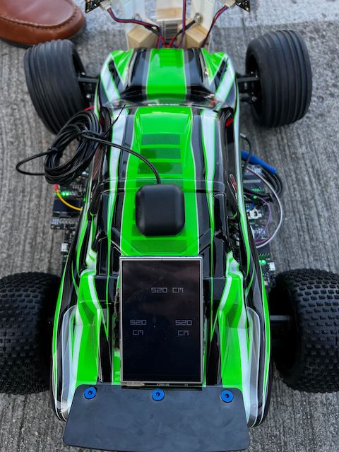
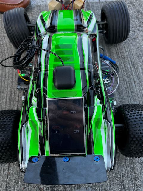
| + | The feature that this LCD has is that the sensor values will turn red if it is within the threshold set by the user. | ||
| + | |||
| + | This is to inform the user that the car is expected to behave in a certain way depending on sensor values. | ||
| − | + | This can mean that the car might stop and reverse if all sensors are within threshold or it can steer in the opposite direction of where the object is detected. | |
| − | |||
| − | |||
=== Technical Challenges === | === Technical Challenges === | ||
| − | + | The only downside of using TFT LCD is that there are a lot of pixels that need to be updated within the callback. This means that the pixel update must meet the deadline of the periodic callback. | |
| + | |||
| + | To overcome this problem, the pixel update was put in 1Hz periodic callback. However, an alternative solution would be to implement an Finite State Machine where one sensor value is updated at a time. | ||
<HR> | <HR> | ||
<BR/> | <BR/> | ||
| − | |||
| − | + | == [https://gitlab.com/lianshi.gan/sjtwo-c-team-gran-turismo/-/tree/GT_Driver_V2 Driver Module] == | |
=== Hardware Design === | === Hardware Design === | ||
| + | |||
| + | {| | ||
| + | |[[File: 2024 GT Driver LCD.png|thumb|left|text-top|1400px|Driver Hardware Layout]] | ||
| + | |} | ||
| + | |||
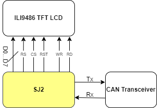
| + | The driver node is attached to a TFT LCD that displays sensor information. This is because the sensors are the most noisy components on the RC car, therefore, reading the values are important to know that the driving algorithm was working correctly. | ||
| + | |||
| + | Since the TFT LCD does not have the SPI pins exposed, therefore, the driver must be connected through 8080-parallel connection. | ||
=== Software Design === | === Software Design === | ||
| − | < | + | |
| + | Similar to other nodes, the driver node also utilizes two periodic callbacks (1Hz and 10Hz). | ||
| + | |||
| + | <span style>'''1 Hz Periodic Callback:'''</span> | ||
| + | |||
| + | 1. In this task, we check for CAN bus status. | ||
| + | |||
| + | <pre> | ||
| + | if (can__is_bus_off(can1)) { | ||
| + | can__reset_bus(can1); | ||
| + | } | ||
| + | </pre> | ||
| + | |||
| + | 2. Update LCD information | ||
| + | |||
| + | <pre> | ||
| + | draw_lcd.c | ||
| + | |||
| + | void draw_lcd__write_sensor_data(dbc_SENSOR_SONARS_s sensor_data_from_can) { | ||
| + | color_e sensor_front_status = WHITE; | ||
| + | color_e sensor_left_status = WHITE; | ||
| + | color_e sensor_right_status = WHITE; | ||
| + | |||
| + | if (sensor_data_from_can.SENSOR_SONARS_front_middle <= driver__get_front_threshold()) { | ||
| + | sensor_front_status = RED; | ||
| + | } | ||
| + | if (sensor_data_from_can.SENSOR_SONARS_front_left <= driver__get_left_threshold()) { | ||
| + | sensor_left_status = RED; | ||
| + | } | ||
| + | if (sensor_data_from_can.SENSOR_SONARS_front_right <= driver__get_right_threshold()) { | ||
| + | sensor_right_status = RED; | ||
| + | } | ||
| + | |||
| + | tft__draw_number(28, 47, 255, 274, ((int)sensor_data_from_can.SENSOR_SONARS_front_left / 100) % 10, | ||
| + | sensor_left_status); | ||
| + | tft__draw_number(52, 71, 255, 274, ((int)sensor_data_from_can.SENSOR_SONARS_front_left / 10 % 10), | ||
| + | sensor_left_status); | ||
| + | tft__draw_number(76, 95, 255, 274, ((int)sensor_data_from_can.SENSOR_SONARS_front_left % 10), sensor_left_status); | ||
| + | |||
| + | tft__draw_number(224, 243, 255, 274, ((int)sensor_data_from_can.SENSOR_SONARS_front_right / 100) % 10, | ||
| + | sensor_right_status); | ||
| + | tft__draw_number(248, 267, 255, 274, ((int)sensor_data_from_can.SENSOR_SONARS_front_right / 10 % 10), | ||
| + | sensor_right_status); | ||
| + | tft__draw_number(272, 291, 255, 274, ((int)sensor_data_from_can.SENSOR_SONARS_front_right % 10), sensor_right_status); | ||
| + | |||
| + | tft__draw_number(120, 139, 116, 135, ((int)sensor_data_from_can.SENSOR_SONARS_front_middle / 100) % 10, | ||
| + | sensor_front_status); | ||
| + | tft__draw_number(144, 163, 116, 135, ((int)sensor_data_from_can.SENSOR_SONARS_front_middle / 10 % 10), | ||
| + | sensor_front_status); | ||
| + | tft__draw_number(168, 187, 116, 135, ((int)sensor_data_from_can.SENSOR_SONARS_front_middle % 10), | ||
| + | sensor_front_status); | ||
| + | } | ||
| + | </pre> | ||
| + | |||
| + | The reason why this was put in 1Hz was because all of the pixels must be updated within the callback or else the MCU will crash. Since the LCD information cannot be updated within 10Hz, therefore, the debug info was put in 1Hz callback. | ||
| + | |||
| + | <span style>'''10 Hz Periodic Callback:'''</span> | ||
| + | |||
| + | 1. Receiving CAN bus information | ||
| + | |||
| + | <pre> | ||
| + | msg_bank.c | ||
| + | |||
| + | void msg_bank__process_all_received_messages(void) { | ||
| + | can__msg_t can_msg = {0}; | ||
| + | |||
| + | while (can__rx(can1, &can_msg, 0)) { | ||
| + | const dbc_message_header_t header = { | ||
| + | .message_id = can_msg.msg_id, | ||
| + | .message_dlc = can_msg.frame_fields.data_len, | ||
| + | }; | ||
| + | |||
| + | if (dbc_decode_SENSOR_SONARS(&sensor_data, header, can_msg.data.bytes)) { | ||
| + | driver__process_sensor_input(sensor_data); | ||
| + | } | ||
| + | |||
| + | if (dbc_decode_COMPASS_CURRENT(&compass_data, header, can_msg.data.bytes)) { | ||
| + | driver__process_geo_controller_directions(compass_data); | ||
| + | } | ||
| + | |||
| + | if (dbc_decode_MOTOR_CMD(&motor_data, header, can_msg.data.bytes)) { | ||
| + | fprintf(stderr, "spd: %d\n", motor_data.MOTOR_CMD_speed_kph); | ||
| + | // ... | ||
| + | } | ||
| + | } | ||
| + | } | ||
| + | </pre> | ||
| + | |||
| + | 2. Setting speed and turning logic | ||
| + | |||
| + | <pre> | ||
| + | driver_logic.c | ||
| + | |||
| + | dbc_DRIVER_CMD_s driver__get_driver_commands(void) { | ||
| + | |||
| + | uint16_t heading = driver__get_compass_heading(); | ||
| + | uint16_t bearing = driver__get_compass_bearing(); | ||
| + | |||
| + | driver__set_speed_based_on_destination_distance(current_compass_data); | ||
| + | |||
| + | if (signal_to_go) { | ||
| + | |||
| + | if (driver__middle_object_detected(MID_THRESHOLD_CM)) { | ||
| + | |||
| + | if (!driver__left_object_detected(LEFT_THRESHOLD_CM) && !driver__right_object_detected(RIGHT_THRESHOLD_CM)) { | ||
| + | |||
| + | if (current_sensor_data.SENSOR_SONARS_front_left > current_sensor_data.SENSOR_SONARS_front_right) { | ||
| + | driver__set_steering_mode(SLIGHT_LEFT_15); | ||
| + | } else if (current_sensor_data.SENSOR_SONARS_front_right > current_sensor_data.SENSOR_SONARS_front_left) { | ||
| + | driver__set_steering_mode(SLIGHT_RIGHT_15); | ||
| + | } else { | ||
| + | driver__set_steering_mode(HALF_RIGHT_30); | ||
| + | } | ||
| + | |||
| + | } else if (driver__left_object_detected(LEFT_THRESHOLD_CM) && | ||
| + | !driver__right_object_detected(RIGHT_THRESHOLD_CM)) { | ||
| + | driver__set_steering_mode(FULL_RIGHT_45); | ||
| + | } else if (!driver__left_object_detected(LEFT_THRESHOLD_CM) && | ||
| + | driver__right_object_detected(RIGHT_THRESHOLD_CM)) { | ||
| + | driver__set_steering_mode(FULL_LEFT_45); | ||
| + | } else { | ||
| + | driver__set_speed(STOP_MODE); | ||
| + | driver__go_backwards_signal(); | ||
| + | } | ||
| + | |||
| + | } else { | ||
| + | if (!driver__left_object_detected(LEFT_THRESHOLD_CM) && !driver__right_object_detected(RIGHT_THRESHOLD_CM)) { | ||
| + | driver__set_servo_according_to_destination(heading, bearing); | ||
| + | } else if (driver__left_object_detected(LEFT_THRESHOLD_CM) && | ||
| + | !driver__right_object_detected(RIGHT_THRESHOLD_CM)) { | ||
| + | driver__set_steering_mode(FULL_RIGHT_45); | ||
| + | } else if (!driver__left_object_detected(LEFT_THRESHOLD_CM) && | ||
| + | driver__right_object_detected(RIGHT_THRESHOLD_CM)) { | ||
| + | driver__set_steering_mode(FULL_LEFT_45); | ||
| + | } else { | ||
| + | driver__set_steering_mode(STRAIGHT); | ||
| + | } | ||
| + | } | ||
| + | |||
| + | } else if (signal_to_backup) { | ||
| + | driver__delay_before_backup(); | ||
| + | if (signal_togo_back) { | ||
| + | driver__go_backwards_for_2s(); | ||
| + | } | ||
| + | } else { | ||
| + | driver__set_speed(STOP_MODE); | ||
| + | driver__set_steering_mode(STRAIGHT); | ||
| + | driver__neutral_on_start_with_gps(); | ||
| + | } | ||
| + | |||
| + | return current_driver_cmd; | ||
| + | } | ||
| + | </pre> | ||
| + | |||
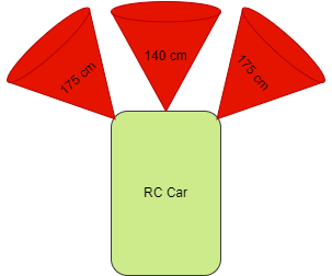
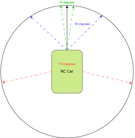
| + | The driving logic based on sensor values can be described through a diagram below: | ||
| + | |||
| + | {| | ||
| + | |[[File: 2024 GT Driver sensor.png|thumb|left|800px|Driving Logic with Obstacles]] | ||
| + | |} | ||
| + | |||
| + | There are three(3) ultrasonic sensors in front of the car mounted facing front, 30-degrees to the left and 30-degrees to the right. | ||
| + | The threshold for middle sensor is set as 140 cm while the left and right sensors are higher at 175 cm. This is because the right and left sensors are tilted, therefore, the threshold must be higher (Pythagorean theorem). | ||
| + | The algorithm is as follow: | ||
| + | * First condition | ||
| + | ** Left sensor: <span style="color:red;">Object Detected</span> | ||
| + | ** Middle sensor: <span style="color:red;">Object Detected</span> | ||
| + | ** Right sensor: <span style="color:red;">Object Detected</span> | ||
| + | <span style>'''Action:'''</span> Stop -> Neutral (1 second) -> Reverse (2s) -> Neutral (1 second) -> Forward again (different direction) | ||
| + | * Second condition | ||
| + | ** Left sensor: <span style="color:green;">Safe</span> | ||
| + | ** Middle sensor: <span style="color:red;">Object Detected</span> | ||
| + | ** Right sensor: <span style="color:green;">Safe</span> | ||
| + | <span style>'''Action:'''</span> Compare left and right sensor for a higher value -> drive to the higher value direction. In the case of both values being equal, the car will simply go right (45 degrees). | ||
| + | * Third condition | ||
| + | ** Left sensor: <span style="color:green;">Safe</span> | ||
| + | ** Middle sensor: <span style="color:red;">Object Detected</span> | ||
| + | ** Right sensor: <span style="color:red;">Object Detected</span> | ||
| + | <span style>'''Action:'''</span> Drive left (45 degrees). | ||
| + | * Fourth condition | ||
| + | ** Left sensor: <span style="color:red;">Object Detected</span> | ||
| + | ** Middle sensor: <span style="color:red;">Object Detected</span> | ||
| + | ** Right sensor: <span style="color:green;">Safe</span> | ||
| + | <span style>'''Action:'''</span> Drive right (45 degrees). | ||
| + | * Fifth condition | ||
| + | ** Left sensor: <span style="color:red;">Object Detected</span> | ||
| + | ** Middle sensor: <span style="color:green;">Safe</span> | ||
| + | ** Right sensor: <span style="color:red;">Object Detected</span> | ||
| + | <span style>'''Action:'''</span> Drive straight. | ||
| + | * Sixth condition | ||
| + | ** Left sensor: <span style="color:green;">Safe</span> | ||
| + | ** Middle sensor: <span style="color:green;">Safe</span> | ||
| + | ** Right sensor: <span style="color:red;">Object Detected</span> | ||
| + | <span style>'''Action:'''</span> Drive left (45 degrees). | ||
| + | * Seventh condition | ||
| + | ** Left sensor: <span style="color:red;">Object Detected</span> | ||
| + | ** Middle sensor: <span style="color:green;">Safe</span> | ||
| + | ** Right sensor: <span style="color:green;">Safe</span> | ||
| + | <span style>'''Action:'''</span> Drive right (45 degrees). | ||
| + | * Eighth condition | ||
| + | ** Left sensor: <span style="color:green;">Safe</span> | ||
| + | ** Middle sensor: <span style="color:green;">Safe</span> | ||
| + | ** Right sensor: <span style="color:green;">Safe</span> | ||
| + | <span style>'''Action:'''</span> Drive to destination. | ||
| + | |||
| + | |||
| + | The driving logic following GPS destination is described below: | ||
| + | |||
| + | {| | ||
| + | |[[File: 2024 GT Driver GPS.png|thumb|left|text-top|800px|Driving Logic According to GPS]] | ||
| + | |} | ||
| + | |||
| + | When RC car is going to the destination, the logic will depend on the current heading and the relative bearing to the destination. | ||
| + | To ensure the RC car did not go wobbly to the destination, the RC car was given three(3) different thresholds that determined by how much the car should turn or if it should go straight. | ||
| + | |||
| + | The logic is divided into 3 parts: | ||
| + | |||
| + | |||
| + | 1. Heading - Bearing is within 10 degrees: | ||
| + | |||
| + | In this case, since the difference is small, the car should go straight until it goes out of 10 degrees threshold | ||
| + | |||
| + | |||
| + | 2. Heading > Bearing | ||
| + | |||
| + | * Angle Diff < 180 degrees: | ||
| + | |||
| + | - Angle Diff <= 45 degrees | ||
| + | |||
| + | In this case, the car will steer left by 15 degrees to adjust. | ||
| + | |||
| + | - Angle Diff <= 115 degrees | ||
| + | |||
| + | In this case, the car will steer left by 30 degrees to adjust. | ||
| + | |||
| + | - Angle Diff < 180 degrees && Angle Diff > 115 degrees | ||
| + | |||
| + | In this case, the car will steer left by 45 degrees to adjust. | ||
| + | |||
| + | * Angle Diff >= 180 degrees: | ||
| + | |||
| + | - Angle Diff <= 225 degrees | ||
| + | |||
| + | In this case, the car will steer right by 15 degrees to adjust. | ||
| + | |||
| + | - Angle Diff <= 295 degrees | ||
| + | |||
| + | In this case, the car will steer right by 30 degrees to adjust. | ||
| + | |||
| + | - Angle Diff < 360 degrees && Angle Diff > 295 degrees | ||
| + | |||
| + | In this case, the car will steer right by 45 degrees to adjust. | ||
| + | |||
| + | |||
| + | 3. Heading < Bearing | ||
| + | |||
| + | * Angle Diff < 180 degrees: | ||
| + | |||
| + | - Angle Diff <= 45 degrees | ||
| + | |||
| + | In this case, the car will steer right by 15 degrees to adjust. | ||
| + | |||
| + | - Angle Diff <= 115 degrees | ||
| + | |||
| + | In this case, the car will steer right by 30 degrees to adjust. | ||
| + | |||
| + | - Angle Diff < 180 degrees && Angle Diff > 115 degrees | ||
| + | |||
| + | In this case, the car will steer right by 45 degrees to adjust. | ||
| + | |||
| + | * Angle Diff >= 180 degrees: | ||
| + | |||
| + | - Angle Diff <= 225 degrees | ||
| + | |||
| + | In this case, the car will steer left by 15 degrees to adjust. | ||
| + | |||
| + | - Angle Diff <= 295 degrees | ||
| + | |||
| + | In this case, the car will steer left by 30 degrees to adjust. | ||
| + | |||
| + | - Angle Diff < 360 degrees && Angle Diff > 295 degrees | ||
| + | |||
| + | In this case, the car will steer left by 45 degrees to adjust. | ||
=== Technical Challenges === | === Technical Challenges === | ||
| − | + | The problem with driving was making it not wobbly by simply adjusting how much the car should turn to destination. | |
| + | |||
| + | The other problem was finding the best threshold for sensor values. Especially since the sensors can be noisy at some point. | ||
<HR> | <HR> | ||
<BR/> | <BR/> | ||
| + | |||
== Mobile Application == | == Mobile Application == | ||
| − | + | [https://github.com/kwu5/243_s2024_gran_turismo_app Github link] | |
| + | |||
| + | === Software Design === | ||
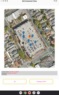
| + | We develop an Android React Native app on with the support from Expo. The app is responsible for receiving the current GPS location of the RC car, as well as the sensor data from the SJ2 board for debug purpose. The app also send command with the destination data to the the Bridge to tell the RC car where to go. | ||
| + | |||
| + | [[File: mobileapp.jpg|200px]] | ||
| + | |||
| + | ==== Feature ==== | ||
| + | * Current destination location, check point locations are marked on the map. | ||
| + | * Sensor data are also shown in the app. | ||
| + | * Click on the map to mark a location and press 'GO' will send out the command and destination to the car. After data is send, the button title will change to "STOP". "Emergency STOP" button is also provided. | ||
| − | |||
| − | + | The command data sent from the app is either "GO!!" or "STOP". In the "GO!!" case, the app also render the destination data that the user mark on the app to the Bridge. Example of data sent will be "GO!!","LAT:37.720681","LONG: -122.422832","STOP". | |
| − | |||
=== Technical Challenges === | === Technical Challenges === | ||
| − | + | *''' Challenge:''' We are facing a issue that when the data is sent from the bridge in 10Hz or 5Hz, the app will stop responding after running for a certain time. | |
| − | + | *''' Solution:''' We modify the bridge data transmitting function so it is called in 1Hz instead. | |
<BR/> | <BR/> | ||
| Line 323: | Line 1,112: | ||
<HR> | <HR> | ||
<BR/> | <BR/> | ||
| + | |||
== Conclusion == | == Conclusion == | ||
| − | + | The project "Gran Turismo" involves the development of an autonomous RC car that is controlled through a mobile application using GPS coordinates. The car's system is based on the integration of multiple controllers which include the Driver, Sensor/Bridge, Geo, and Motor nodes. These nodes communicate over a Controller Area Network (CAN) bus, using FreeRTOS to handle tasks such as data gathering, processing, and decision-making for navigation and obstacle avoidance. | |
| − | + | The project is a collaborative effort amongst Daniel Zhao Yeung, Suryanto Phienanda, Kaijian Wu, and Lianshi Gan, who employed their expertise to create a smart RC car. The team planned and executed each phase over several weeks, with each new prototype incorporating innovative features like as Bluetooth for communication, sensors for obstacle avoidance, and GPS navigation. The car uses a variety of hardware components, including ultrasonic sensors, GPS modules, and a Bluetooth module, which are seamlessly integrated with powerful software algorithms to provide efficient inter-module communication and data management. Despite difficulties such as controlling data transmission rates and integrating Bluetooth technology, the team successfully altered techniques to ensure smooth functioning.After all, "Gran Turismo" demonstrates the successful integration of complex hardware and software to create a fully autonomous navigation system for RC vehicles. | |
=== Project Video === | === Project Video === | ||
=== Project Source Code === | === Project Source Code === | ||
| + | |||
| + | Project GitLab Repository | ||
| + | |||
| + | [https://gitlab.com/lianshi.gan/sjtwo-c-team-gran-turismo GitLab Link] | ||
=== Advise for Future Students === | === Advise for Future Students === | ||
| − | + | ||
| + | * Whoever is working on Motor node should start immediately to find out how the ESC works. | ||
| + | * Implement PID controller for Motor as soon as possible to make your car operate smoothly. | ||
| + | * Look at all previous team reports, not to copy their code or to order same parts, but to find out what you can do to stand out and be different from previous teams. For instance, since the beginning of the project, we always wanted to put the cover back on. To achieve this, we tried to make our design as light and as small as possible. We avoided using plexiglass since it would have made it impossible to put the cover back on with plexiglass. | ||
| + | * Order extra parts (in case you break something by accident) | ||
| + | * Be passionate and willing to learn regardless of what your major is. If you have never touched wires or hardware stuff before, learn and get used to it. You need at least one person on your team who can work with wires and is handy with hardware stuff. | ||
| + | * If possible, learn how to make PCB. It is not that hard and it is pretty fun. | ||
| + | * DO NOT GET HC-SR04!!! Try to get distance sensors that you can read through ADC or I2C. HC-SR04 relies on the high time of Echo pin and the echo pin outputs 5V while your GPIO reads 3.3V. Fortunately, SJ2 GPIOs are 5V tolerant. To get HC-SR04 work with SJ2, you need to create a voltage divider so that you can read 3.3V from the echo pin. However, I would suggest future students to simply avoid HC-SR04. | ||
=== Acknowledgement === | === Acknowledgement === | ||
| − | + | First and foremost, we would like to thank Professor Preetpal Kang for the amazing semester and a wonderful project. We all have learned so much from this project. While some of us had to stay up really late to complete this project, in the end, it was all worth it. We have learned so much about CAN bus and more from this project alone. | |
| + | |||
| + | Second, we would like to thank Kyle Kwong and Ninaad for being amazing Teacher Assistants throughout the semester. Thank you for everything that you guys have helped us with and grading our project and assignments. | ||
| + | |||
| + | Lastly, we would like to thank Traxxas for creating such an amazing RC car that we could use to complete this project. | ||
Latest revision as of 03:52, 26 May 2024
Contents
Gran Turismo
Abstract
"The Gran Turismo" is an autonomous RC car designed to navigate to a specified destination using GPS coordinates, communicated via a mobile application. The car integrates four microcontrollers (Driver, Sensor/Bridge, Geo, and Motor nodes) which communicate over a Controller Area Network (CAN) bus. It utilizes FreeRTOS to manage periodic tasks for data gathering, processing, and decision-making, ensuring effective obstacle detection and avoidance while maintaining the intended path.
Introduction
The project was divided into 5 nodes:
- Sensor / Bridge node
- Motor node
- Geo node
- Driver / LCD node
- Mobile Application
Team Members & Responsibilities
Team Members (From Left to Right):
- Kaijian Wu
- Daniel Zhao Yeung
- Suryanto Phienanda
- Lianshi Gan
Gitlab Project Link - C243_GT
| Team Members | Task Responsibility |
|---|---|
|
|
| |
|
|
|
|
Schedule
| Week# | Start Date | End Date | Task | Status |
|---|---|---|---|---|
| 1 | 03/04/2024 | 03/10/2024 |
|
Completed |
| 2 | 03/11/2024 | 03/17/2024 |
|
Completed |
| 3 | 03/18/2024 | 03/24/2024 |
|
Completed |
| 4 | 03/25/2024 | 03/31/2024 |
|
Completed |
| 5 | 04/01/2024 | 04/07/2024 |
|
Completed |
| 6 | 04/08/2024 | 04/14/2024 |
|
Completed |
| 7 | 04/15/2024 | 04/21/2024 |
|
Completed |
| 8 | 04/22/2024 | 04/28/2024 |
|
Completed |
| 9 | 04/29/2024 | 05/05/2024 |
|
Completed |
| 10 | 05/06/2024 | 05/12/2024 |
|
Completed |
| 11 | 05/13/2024 | 05/19/2024 |
|
Completed |
Prototype 1
Prototype 2
Parts List & Cost
| Item# | Part Desciption | Vendor | Qty | Cost |
|---|---|---|---|---|
| 1 | RC Car | Traxxas | 1 | $250.00 |
| 2 | CAN Transceivers MCP2551-I/P | Microchip [1] | 4 | Free Samples |
| 3 | Ultrasonic Sensor URM09 from DFRobots | dfrobot [2] | 3 | $8.00 * 3 |
| 4 | DSD TECH HM-10 Bluetooth 4.0 BLE | Amazon [3] | 1 | $12.00 |
| 5 | Tilt Compensated Magnetic Compass (CMPS14) | RobotShop [4] | 1 | $41.00 |
| 6 | GT-U7 GPS Module GPS Receiver | Amazon [5] | 1 | $15.00 |
| 7 | Bingfu Waterproof Active GPS Navigation Antenna | Amazon [6] | 1 | $41.00 |
| 8 | LM393 Wheel Encoder | Amazon [7] | 1 | $8.49 |
| 8 | ILI9486 TFT LCD | Amazon [8] | 1 | $17.29 |
| 9 | LED Headlights | Amazon [9] | 1 | $7.95 |
CAN Communication
Hardware Design
Each Node is connected to a CAN transceiver where CAN receiver (RX) on SJ2 is connected to CAN Transceiver receiver (RX) and CAN transmitter (TX) on SJ2 is connected to CAN Transceiver transmitter (TX). The CAN transceivers are then connected to each other through CANH and CANL lines that are connected to 120Ω terminating resistors to ensure the integrity of the signals on CANH and CANL lines.
DBC File
BO_ 100 DRIVER_CMD: 3 DRIVER
 SG_ DRIVER_CMD_heartbeat : 0|1@1+ (1,0) [0|0] "" SENSOR,MOTOR
 SG_ DRIVER_CMD_steer : 1|4@1+ (1,-5) [-5|5] "degrees" MOTOR
 SG_ MOTOR_CMD_drive : 5|4@1+ (1,-2) [-2|5] "kph" MOTOR

BO_ 105 GPS_CURRENT_COORD : 8 GPS
 SG_ GPS_CURRENT_COORD_lat_degree : 0|8@1- (1,-90) [-90|90] "degrees" BRIDGE
 SG_ GPS_CURRENT_COORD_lat_minutes : 8|6@1+ (1,0) [0|60] "minutes" BRIDGE
 SG_ GPS_CURRENT_COORD_lat_seconds : 14|16@1+ (0.001,0) [0|60] "seconds" BRIDGE
 SG_ GPS_CURRENT_COORD_long_degree : 30|9@1- (1,-180) [-180|180] "degrees" BRIDGE
 SG_ GPS_CURRENT_COORD_long_minutes : 39|6@1+ (1,0) [0|60] "minutes" BRIDGE
 SG_ GPS_CURRENT_COORD_long_seconds : 45|16@1+ (0.001,0) [0|60] "seconds" BRIDGE

BO_ 110 GPS_DESTINATION_LOCATION: 8 BRIDGE
 SG_ GPS_DESTINATION_LOCATION_lat_degree : 0|8@1- (1,-90) [-90|90] "degrees" GPS
 SG_ GPS_DESTINATION_LOCATION_lat_minutes : 8|6@1+ (1,0) [0|60] "minutes" GPS
 SG_ GPS_DESTINATION_LOCATION_lat_seconds : 14|16@1+ (0.001,0) [0|60] "seconds" GPS
 SG_ GPS_DESTINATION_LOCATION_long_degree : 30|9@1- (1,-180) [-180|180] "degrees" GPS
 SG_ GPS_DESTINATION_LOCATION_long_minutes : 39|6@1+ (1,0) [0|60] "minutes" GPS
 SG_ GPS_DESTINATION_LOCATION_long_seconds : 45|16@1+ (0.001,0) [0|60] "seconds" GPS

BO_ 120 COMPASS_CURRENT: 7 COMPASS
  SG_ COMPASS_CURRENT_heading : 0|12@1+ (1,0) [0|359.9] "degrees" DRIVER
  SG_ COMPASS_CURRENT_bearing : 12|12@1+ (1,0) [0|359.9] "degrees" DRIVER
  SG_ COMPASS_CURRENT_distance_to_dest : 24|32@1+ (0.1,0) [0|0] "meters" DRIVER

BO_ 200 SENSOR_SONARS: 8 SENSOR
 SG_ SENSOR_SONARS_front_left : 0|13@1+ (0.1,0) [0|520] "cm" DRIVER
 SG_ SENSOR_SONARS_front_right : 13|13@1+ (0.1,0) [0|520] "cm" DRIVER
 SG_ SENSOR_SONARS_front_middle : 26|13@1+ (0.1,0) [0|520] "cm" DRIVER
 SG_ SENSOR_SONARS_rear : 39|13@1+ (0.1,0) [0|520] "cm" DRIVER

BO_ 300 MOTOR_CMD: 2 MOTOR
 SG_ MOTOR_CMD_speed_kph : 0|8@1+ (1,0) [0|35] "kph" DRIVER
 SG_ MOTOR_CMD_angle : 8|8@1+ (1,0) [-5|5] "degrees" DRIVER
Sensor and Bridge ECU
Hardware Design
Ultrasonic Sensor
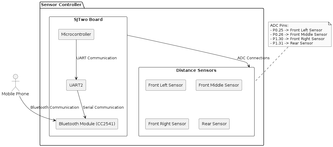
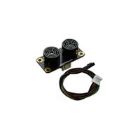
Selecting the appropriate distance sensor is crucial for the success of the project. Our team chose the Ultrasonic Sensor URM09 from DFRobots due to its ease of use and cost-effectiveness. The URM09 offers multiple communication protocols, and we opted for the I2C package to simplify the configuration and reading process, allowing us to focus on the overall system integration.
- Ultra-Sonic Sensor URM09 (I2C Protocol)
- Supply Voltage: 3.3~5.5V DC
- Operating Current: 20mA
- Operating Temperature Range: -10℃~+70℃
- Measurement Range: 2cm~500cm (can be set)
- Resolution: 1cm
- Accuracy: 1%
- Frequency: 50Hz Max
- Dimension: 47mm × 22 mm/1.85” × 0.87”
Bluetooth Module
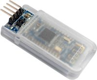
For the communication between the Mobile app and the RC car. We use the DSD TECH HM-10 Bluetooth 4.0 BLE module. This module communicate with the SJ2 board by using UART. It transmits raw data between mobile app and bridge. It is lightweight and has small size.
- DSD TECH HM-10 Bluetooth 4.0 BLE
- Operating voltage: 3.3V
- Core module: MH-10
- Support device: iOS device(iphone and ipad). But does not support the version is lower than the android 4.3 phone(it don't support classic bluetooth 2.0 spp features)
Software Design
Preiocally tasks
- receiving data
- Current coordinate from Geo ECU (Geo node)
- Destination coordinates, command data from Mobile App (App)
- Sensor data from sensor (Ultrasonic Sensor URM09)
- sending data:
- Destination coordinates, sensor data to Driver ECU (Driver node)
- Sensor data to app (App)
void periodic_callbacks__1Hz(uint32_t callback_count) {
  if (can__is_bus_off(can1)) {
    can__reset_bus(can1);
    gpio__toggle(board_io__get_led0());
  }
  can_bus_handler__receive_current_gps();
  can_bus_handler_service_mia_1Hz();
  const dbc_GPS_CURRENT_COORD_s current_coord = can_bus_handler__get_received_current_gps();

  bluetooth__send_current_gps_to_app(current_coord);
  bluetooth__send_sensor_data_to_app();
}

void periodic_callbacks__10Hz(uint32_t callback_count) {
  bluetooth__receive_all_data_from_app();

  can_bus_handler__transmit_sensors();
  can_bus_handler__transmit_command();
  can_bus_handler__transmit_destination_gps();
}
Technical Challenges
Bluetooth Module
- Challenge: : Due to its design, it can read/send a string up to 20 characters at a time. Any string more than 20 characters will be break into 2 lines automatically and process. The datasheet provides limited information when developing the Bluetooth module.
- Solution: On SJ2 board side, we break out data into serval strings and pad '0' into some data string to ensure it is send in exact 20 characters.
Sensor Module
Transmitting Sensor Data
Since there are some "printf" were set up for debugging sensor data, we transmitting data on 5Hz in order to avoid crashing the SJ2 board. It wasn't any issue when we doing unit testing and obstacle avoiding testing run. However, the low 5 Hz cause turning delay when we actually run the RC car in high speed. Remember to ensure sensor data transmitting at least 10 to 20 Hz.
void periodic_callbacks__10Hz(uint32_t callback_count) {
  bluetooth__receive_all_data_from_app();


  can_bus_handler__transmit_sensors();

  can_bus_handler__transmit_command();
  can_bus_handler__transmit_destination_gps();
}
Configure 4 ADC channels
We load the distance sensor data by ADC channel. There are only 3 channels ready to use on SJ2 board. Need to modify P0_26 as below to unlock ADC:
static void distance__configure_all_adc_pins(void) {
  LPC_IOCON->P0_25 &= ~(3 << 3);
  LPC_IOCON->P0_25 &= ~(1 << 7);

  LPC_IOCON->P0_26 &= ~(3 << 3);
  LPC_IOCON->P0_26 &= ~(1 << 16);
  LPC_IOCON->P0_26 &= ~(1 << 7);

  LPC_IOCON->P1_30 &= ~(3 << 3);
  LPC_IOCON->P1_30 &= ~(1 << 7);

  LPC_IOCON->P1_31 &= ~(3 << 3);
  LPC_IOCON->P1_31 &= ~(1 << 7);
}
Motor ECU
Hardware Design
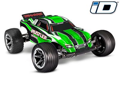
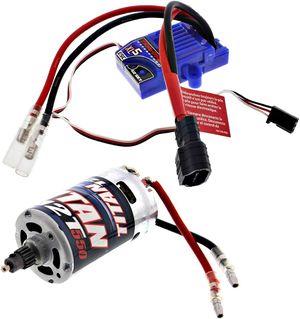
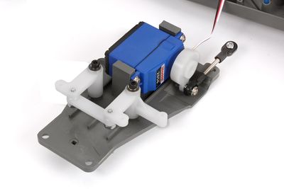
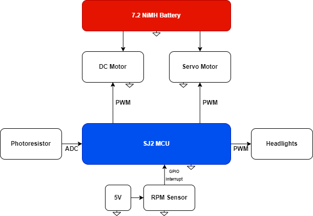
Traxxas RC car is controlled using a built-in ESC provided by Traxxas. Since there is not a single documentation on how Traxxas ESC works, it needed to be decoded manually to understand how the ESC works.
Based on the observation, it seems that Traxxas ESC must be initialized with neutral PWM signal, which is indicated by a red LED on ESC. This is only applicable to the DC motor.
With the initialized PWM frequency of 100Hz, it was observed that PWM signal of 16.0f is the neutral signal for DC motor while PWM signal of 14.0f is the neutral signal for servo motor.
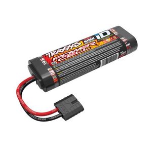
Both DC and servo motor were powered by 7.2V NiMH battery from Traxxas.
To control the speed of the RC car, an RPM sensor with a wheel encoder were needed to keep track of the current speed of the car.
A PID controller was implemented so that the DC motor could be incremented properly without any visible overshoot.
Since the RC car is also capable of reversing, the PID controller must also be capable of reversing properly. However, to reverse, the ESC must first be set to neutral before decreasing the PWM.
To avoid any damage on the DC motor, the ESC was given 1-second to be neutral before reversing.
Details on how Traxxas XL-5 ESC functions (DC Motor):
- PWM 16.0 -- Neutral
- PWM < 16.0 -- Reverse
- PWM > 16.0 -- Forward
Details on how Servo Motor functions:
- PWM 14.0 -- Neutral
- PWM < 14.0 -- Left
- PWM > 14.0 -- Right
Software Design
In Motor node, two periodic callbacks were utilized (1 Hz and 10 Hz).
1 Hz Periodic Callback:
1. Checking for photoresistor value (mounted on the windshield of the car)
headlight.c

void headlight__toggle(void) {
  if (photoresistor__get_reading(ADC__CHANNEL_4) > 1500) {
    headlight__on();
  } else {
    headlight__off();
  }
}
2. Checking for CAN bus status
if (can__is_bus_off(can1)) {
  can__reset_bus(can1);
}
10 Hz Periodic Callback:
1. Receive all messages from CAN transceiver
can_bus_handler.c

void can_bus_handler__receive_all_messages(void) {
  can__msg_t can_msg = {0};
  dbc_DRIVER_CMD_s new_driver_cmd = {0};

  while (can__rx(can1, &can_msg, 0)) {
    dbc_message_header_t header = {.message_dlc = can_msg.frame_fields.data_len, .message_id = can_msg.msg_id};

    if (dbc_decode_DRIVER_CMD(&new_driver_cmd, header, can_msg.data.bytes)) {
      motor__receive_driver_message(new_driver_cmd);
    }
  }
}
2. Transmit messages to CAN transceiver
can_bus_handler.c
void can_bus_handler__transmit_messages(void) {
dbc_MOTOR_CMD_s current_motor_cmd = motor__get_current_motor_cmd();
dbc_encode_and_send_MOTOR_CMD(NULL, ¤t_motor_cmd);
}
3. Adjust duty cycle to reach the desired speed
motor.c

void motor__pid(void) {
  rc_car_current_speed = rpm_sensor__get_current_speed_kph();

  float error = rc_car_target_speed - rc_car_current_speed;

  if ((int)error != 0) {
    motor__pid_update_p_term(error);
    motor__pid_update_i_term(error);
    motor__pid_update_d_term(error);

    motor__pid_update_pwm_duty_cycle(PID_P_TERM, PID_I_TERM, PID_D_TERM);
  }

  motor__set_dc_motor_speed(rc_car_duty_cycle);
}
where the P-term is as follow:
...
error = target_speed - current_speed;
...

static void motor__pid_update_p_term(float error) { PID_P_TERM = PID_KP * error; }
the I-term is as follow:
static void motor__pid_update_i_term(float error) {
  PID_I_TMP += error;

  if (PID_I_TMP > PID_IMAX_ERROR) {
    PID_I_TMP = PID_IMAX_ERROR;
  } else if (PID_I_TMP < PID_IMIN_ERROR) {
    PID_I_TMP = PID_IMIN_ERROR;
  }

  PID_I_TERM = PID_KI * PID_I_TMP;
}
the D-term is as follow:
static void motor__pid_update_d_term(float error) {
  PID_D_TERM = PID_KD * (PID_D_TMP - error);
  PID_D_TMP = error;
}
then, the duty cycle is updated as follow:
static void motor__pid_update_pwm_duty_cycle(float pterm, float iterm, float dterm) {
  if (current_driver_cmd.DRIVER_CMD_drive < 0) {
    rc_car_duty_cycle = DC_NEUTRAL_DUTY_CYCLE - (pterm + iterm + dterm);
  } else {
    rc_car_duty_cycle = DC_NEUTRAL_DUTY_CYCLE + (pterm + iterm + dterm);
  }
}
Technical Challenges
- Decoding Traxxas ESC
Since there is not a single documentation on Traxxas ESC, the ESC must be decoded manually. Another hack that could be done to help decoding is by connecting the white wire (signal wire) of DC and servo to a logic analyzer and read the data through a software. However, simply by spending around 30-mins, the ESC should be understood.
- Figuring out KP, KI and KD term
If the engineer is not familiar with PID, this will be challenging since not understanding how these terms affect PID controller could cause the car to simply overshoot and crash. To solve this problem, simply put the RC car on top of a box with the rear wheels floating, then configure PID and see how each term affects the speed of the car. It is extremely helpful to read an article about PID first.
- Setting up RPM sensor
This might be the most challenging part (especially if one is not used to tinkering with hardware). To read the RPM, I had three options at first: RPM sensor, Reed sensor or Hall effect sensor. The reason why RPM sensor was selected was because the other sensors rely on magnetic field. Since the placement for the sensor would be close to DC motor, there is a high possibility that the reading will be affected by the magnetic field from DC motor. With wheel encoder, the magnetic field will not have any effect on the reading.
Geographical Controller
Hardware Design
Tilt Compensated Magnetic Compass (CMPS14)
- Features a 3-axis gyro and 3-axis magnetometer
- Offers equally impressive performance to the CMPS12
- Allows the calibration to be stopped and instead rely on a static calibration profile
The CMPS14 Tilt Compensated Magnetic Compass is equipped with a three-axis magnetometer, gyroscope, and accelerometer. It uses the advanced BNO080 to run algorithms that correct for any errors caused by the PCB tilting. Additionally, the module offers the option to halt calibration and use a static calibration profile instead.
- Antenna: Radio
- Brand: BINGFU
- Color with U.FL Cable
- Impedance: 50 Ohm
- Maximum Range: 3 Meters
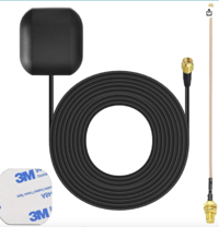
The Bingfu Waterproof Active GPS Navigation Antenna is a durable, water-resistant antenna with an adhesive mount and an SMA male connection. It comes with a 6-inch coaxial cable that connects from U.FL IPX IPEX to an SMA female connector. This antenna is designed for use with GPS modules and receivers to enhance tracking capabilities.
GT-U7 GPS Module GPS Receiver
- Brand: Geekstory
- Map Type: Satellite
- Item Weight: 0.2 Ounces
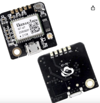
The GT-U7 is a compact GPS module with low power usage and high sensitivity. It uses a 7th generation chip and is compatible with NEO-6M software. This module excels in difficult environments like urban canyons and dense forests, providing precise location tracking. It includes a USB interface for easy connection to a computer using a standard phone cable, and comes with an active antenna.
Software Design
Periodic callbacks are scheduled at 10 Hz.
 void periodic_callbacks__10Hz(uint32_t callback_count) {
 can_bus_handler__handle_all_messages();
 can_bus_handler__transmit_gps();
 can_bus_handler__transmit_compass();
 }
Preiocally tasks
- receiving data
- Heading from compass (cmps14)
- Destination coordinates from Mobile App
- Current coordinates from GPS receiver (gt-u7)
- sending data:
- Current coordinates to mobile app
- Distance and bearing (from calculation of current and destination coordinates) to driver controller
- Heading (from cmps14) to driver controller
Technical Challenges
- Getting accurate data of compass
- Follow the calibration procedure in the CMPS14 user manual.
- Avoid areas with excessive wiring or magnets nearby.
- Use the LED on the SJ2 board to indicate the calibration level.
- Only transfer data when the `readyBit` is greater than 0.
TFT LCD
Software Design
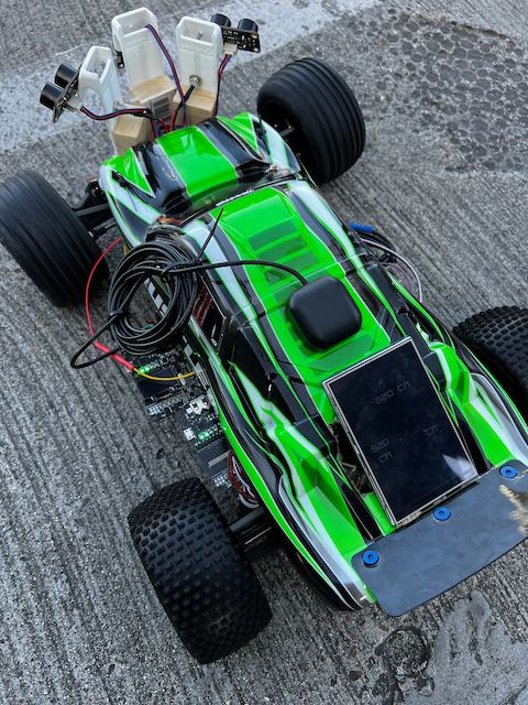
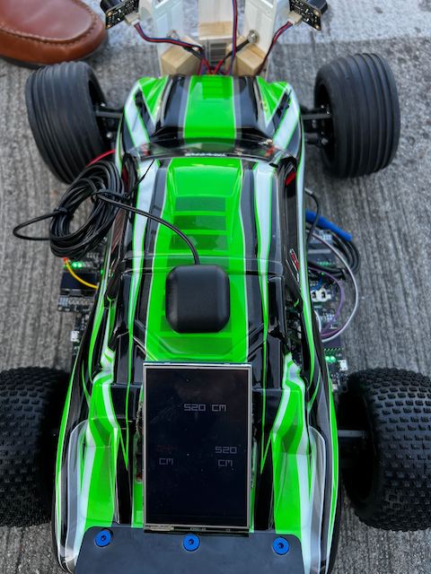
The TFT LCD is updated every 1Hz. This is because the SJ2 will crash in 10Hz due to the MCU incapable of meeting the deadline of 0.1 second.
An alternative to this will be by implementing a state machine where only one sensor value will be updated at every callback.
However, the downside of implementing an FSM is that the value of the sensor will be inaccurate by 0.1 second.
1Hz Periodic Callback
void draw_lcd__write_sensor_data(dbc_SENSOR_SONARS_s sensor_data_from_can) {
  color_e sensor_front_status = WHITE;
  color_e sensor_left_status = WHITE;
  color_e sensor_right_status = WHITE;

  if (sensor_data_from_can.SENSOR_SONARS_front_middle <= driver__get_front_threshold()) {
    sensor_front_status = RED;
  }
  if (sensor_data_from_can.SENSOR_SONARS_front_left <= driver__get_left_threshold()) {
    sensor_left_status = RED;
  }
  if (sensor_data_from_can.SENSOR_SONARS_front_right <= driver__get_right_threshold()) {
    sensor_right_status = RED;
  }

  tft__draw_number(28, 47, 255, 274, ((int)sensor_data_from_can.SENSOR_SONARS_front_left / 100) % 10,
                   sensor_left_status);
  tft__draw_number(52, 71, 255, 274, ((int)sensor_data_from_can.SENSOR_SONARS_front_left / 10 % 10),
                   sensor_left_status);
  tft__draw_number(76, 95, 255, 274, ((int)sensor_data_from_can.SENSOR_SONARS_front_left % 10), sensor_left_status);

  tft__draw_number(224, 243, 255, 274, ((int)sensor_data_from_can.SENSOR_SONARS_front_right / 100) % 10,
                   sensor_right_status);
  tft__draw_number(248, 267, 255, 274, ((int)sensor_data_from_can.SENSOR_SONARS_front_right / 10 % 10),
                   sensor_right_status);
  tft__draw_number(272, 291, 255, 274, ((int)sensor_data_from_can.SENSOR_SONARS_front_right % 10), sensor_right_status);

  tft__draw_number(120, 139, 116, 135, ((int)sensor_data_from_can.SENSOR_SONARS_front_middle / 100) % 10,
                   sensor_front_status);
  tft__draw_number(144, 163, 116, 135, ((int)sensor_data_from_can.SENSOR_SONARS_front_middle / 10 % 10),
                   sensor_front_status);
  tft__draw_number(168, 187, 116, 135, ((int)sensor_data_from_can.SENSOR_SONARS_front_middle % 10),
                   sensor_front_status);
}
The feature that this LCD has is that the sensor values will turn red if it is within the threshold set by the user.
This is to inform the user that the car is expected to behave in a certain way depending on sensor values.
This can mean that the car might stop and reverse if all sensors are within threshold or it can steer in the opposite direction of where the object is detected.
Technical Challenges
The only downside of using TFT LCD is that there are a lot of pixels that need to be updated within the callback. This means that the pixel update must meet the deadline of the periodic callback.
To overcome this problem, the pixel update was put in 1Hz periodic callback. However, an alternative solution would be to implement an Finite State Machine where one sensor value is updated at a time.
Driver Module
Hardware Design
The driver node is attached to a TFT LCD that displays sensor information. This is because the sensors are the most noisy components on the RC car, therefore, reading the values are important to know that the driving algorithm was working correctly.
Since the TFT LCD does not have the SPI pins exposed, therefore, the driver must be connected through 8080-parallel connection.
Software Design
Similar to other nodes, the driver node also utilizes two periodic callbacks (1Hz and 10Hz).
1 Hz Periodic Callback:
1. In this task, we check for CAN bus status.
if (can__is_bus_off(can1)) {
    can__reset_bus(can1);
  }
2. Update LCD information
draw_lcd.c

void draw_lcd__write_sensor_data(dbc_SENSOR_SONARS_s sensor_data_from_can) {
  color_e sensor_front_status = WHITE;
  color_e sensor_left_status = WHITE;
  color_e sensor_right_status = WHITE;

  if (sensor_data_from_can.SENSOR_SONARS_front_middle <= driver__get_front_threshold()) {
    sensor_front_status = RED;
  }
  if (sensor_data_from_can.SENSOR_SONARS_front_left <= driver__get_left_threshold()) {
    sensor_left_status = RED;
  }
  if (sensor_data_from_can.SENSOR_SONARS_front_right <= driver__get_right_threshold()) {
    sensor_right_status = RED;
  }

  tft__draw_number(28, 47, 255, 274, ((int)sensor_data_from_can.SENSOR_SONARS_front_left / 100) % 10,
                   sensor_left_status);
  tft__draw_number(52, 71, 255, 274, ((int)sensor_data_from_can.SENSOR_SONARS_front_left / 10 % 10),
                   sensor_left_status);
  tft__draw_number(76, 95, 255, 274, ((int)sensor_data_from_can.SENSOR_SONARS_front_left % 10), sensor_left_status);

  tft__draw_number(224, 243, 255, 274, ((int)sensor_data_from_can.SENSOR_SONARS_front_right / 100) % 10,
                   sensor_right_status);
  tft__draw_number(248, 267, 255, 274, ((int)sensor_data_from_can.SENSOR_SONARS_front_right / 10 % 10),
                   sensor_right_status);
  tft__draw_number(272, 291, 255, 274, ((int)sensor_data_from_can.SENSOR_SONARS_front_right % 10), sensor_right_status);

  tft__draw_number(120, 139, 116, 135, ((int)sensor_data_from_can.SENSOR_SONARS_front_middle / 100) % 10,
                   sensor_front_status);
  tft__draw_number(144, 163, 116, 135, ((int)sensor_data_from_can.SENSOR_SONARS_front_middle / 10 % 10),
                   sensor_front_status);
  tft__draw_number(168, 187, 116, 135, ((int)sensor_data_from_can.SENSOR_SONARS_front_middle % 10),
                   sensor_front_status);
}
The reason why this was put in 1Hz was because all of the pixels must be updated within the callback or else the MCU will crash. Since the LCD information cannot be updated within 10Hz, therefore, the debug info was put in 1Hz callback.
10 Hz Periodic Callback:
1. Receiving CAN bus information
msg_bank.c

void msg_bank__process_all_received_messages(void) {
  can__msg_t can_msg = {0};

  while (can__rx(can1, &can_msg, 0)) {
    const dbc_message_header_t header = {
        .message_id = can_msg.msg_id,
        .message_dlc = can_msg.frame_fields.data_len,
    };

    if (dbc_decode_SENSOR_SONARS(&sensor_data, header, can_msg.data.bytes)) {
      driver__process_sensor_input(sensor_data);
    }

    if (dbc_decode_COMPASS_CURRENT(&compass_data, header, can_msg.data.bytes)) {
      driver__process_geo_controller_directions(compass_data);
    }

    if (dbc_decode_MOTOR_CMD(&motor_data, header, can_msg.data.bytes)) {
      fprintf(stderr, "spd: %d\n", motor_data.MOTOR_CMD_speed_kph);
      // ...
    }
  }
}
2. Setting speed and turning logic
driver_logic.c

dbc_DRIVER_CMD_s driver__get_driver_commands(void) {

  uint16_t heading = driver__get_compass_heading();
  uint16_t bearing = driver__get_compass_bearing();

  driver__set_speed_based_on_destination_distance(current_compass_data);

  if (signal_to_go) {

    if (driver__middle_object_detected(MID_THRESHOLD_CM)) {

      if (!driver__left_object_detected(LEFT_THRESHOLD_CM) && !driver__right_object_detected(RIGHT_THRESHOLD_CM)) {

        if (current_sensor_data.SENSOR_SONARS_front_left > current_sensor_data.SENSOR_SONARS_front_right) {
          driver__set_steering_mode(SLIGHT_LEFT_15);
        } else if (current_sensor_data.SENSOR_SONARS_front_right > current_sensor_data.SENSOR_SONARS_front_left) {
          driver__set_steering_mode(SLIGHT_RIGHT_15);
        } else {
          driver__set_steering_mode(HALF_RIGHT_30);
        }

      } else if (driver__left_object_detected(LEFT_THRESHOLD_CM) &&
                 !driver__right_object_detected(RIGHT_THRESHOLD_CM)) {
        driver__set_steering_mode(FULL_RIGHT_45);
      } else if (!driver__left_object_detected(LEFT_THRESHOLD_CM) &&
                 driver__right_object_detected(RIGHT_THRESHOLD_CM)) {
        driver__set_steering_mode(FULL_LEFT_45);
      } else {
        driver__set_speed(STOP_MODE);
        driver__go_backwards_signal();
      }

    } else {
      if (!driver__left_object_detected(LEFT_THRESHOLD_CM) && !driver__right_object_detected(RIGHT_THRESHOLD_CM)) {
        driver__set_servo_according_to_destination(heading, bearing);
      } else if (driver__left_object_detected(LEFT_THRESHOLD_CM) &&
                 !driver__right_object_detected(RIGHT_THRESHOLD_CM)) {
        driver__set_steering_mode(FULL_RIGHT_45);
      } else if (!driver__left_object_detected(LEFT_THRESHOLD_CM) &&
                 driver__right_object_detected(RIGHT_THRESHOLD_CM)) {
        driver__set_steering_mode(FULL_LEFT_45);
      } else {
        driver__set_steering_mode(STRAIGHT);
      }
    }

  } else if (signal_to_backup) {
    driver__delay_before_backup();
    if (signal_togo_back) {
      driver__go_backwards_for_2s();
    }
  } else {
    driver__set_speed(STOP_MODE);
    driver__set_steering_mode(STRAIGHT);
    driver__neutral_on_start_with_gps();
  }

  return current_driver_cmd;
}
The driving logic based on sensor values can be described through a diagram below:
There are three(3) ultrasonic sensors in front of the car mounted facing front, 30-degrees to the left and 30-degrees to the right. The threshold for middle sensor is set as 140 cm while the left and right sensors are higher at 175 cm. This is because the right and left sensors are tilted, therefore, the threshold must be higher (Pythagorean theorem). The algorithm is as follow:
- First condition
- Left sensor: Object Detected
- Middle sensor: Object Detected
- Right sensor: Object Detected
Action: Stop -> Neutral (1 second) -> Reverse (2s) -> Neutral (1 second) -> Forward again (different direction)
- Second condition
- Left sensor: Safe
- Middle sensor: Object Detected
- Right sensor: Safe
Action: Compare left and right sensor for a higher value -> drive to the higher value direction. In the case of both values being equal, the car will simply go right (45 degrees).
- Third condition
- Left sensor: Safe
- Middle sensor: Object Detected
- Right sensor: Object Detected
Action: Drive left (45 degrees).
- Fourth condition
- Left sensor: Object Detected
- Middle sensor: Object Detected
- Right sensor: Safe
Action: Drive right (45 degrees).
- Fifth condition
- Left sensor: Object Detected
- Middle sensor: Safe
- Right sensor: Object Detected
Action: Drive straight.
- Sixth condition
- Left sensor: Safe
- Middle sensor: Safe
- Right sensor: Object Detected
Action: Drive left (45 degrees).
- Seventh condition
- Left sensor: Object Detected
- Middle sensor: Safe
- Right sensor: Safe
Action: Drive right (45 degrees).
- Eighth condition
- Left sensor: Safe
- Middle sensor: Safe
- Right sensor: Safe
Action: Drive to destination.
The driving logic following GPS destination is described below:
When RC car is going to the destination, the logic will depend on the current heading and the relative bearing to the destination. To ensure the RC car did not go wobbly to the destination, the RC car was given three(3) different thresholds that determined by how much the car should turn or if it should go straight.
The logic is divided into 3 parts:
1. Heading - Bearing is within 10 degrees:
In this case, since the difference is small, the car should go straight until it goes out of 10 degrees threshold
2. Heading > Bearing
- Angle Diff < 180 degrees:
- Angle Diff <= 45 degrees
In this case, the car will steer left by 15 degrees to adjust.
- Angle Diff <= 115 degrees
In this case, the car will steer left by 30 degrees to adjust.
- Angle Diff < 180 degrees && Angle Diff > 115 degrees
In this case, the car will steer left by 45 degrees to adjust.
- Angle Diff >= 180 degrees:
- Angle Diff <= 225 degrees
In this case, the car will steer right by 15 degrees to adjust.
- Angle Diff <= 295 degrees
In this case, the car will steer right by 30 degrees to adjust.
- Angle Diff < 360 degrees && Angle Diff > 295 degrees
In this case, the car will steer right by 45 degrees to adjust.
3. Heading < Bearing
- Angle Diff < 180 degrees:
- Angle Diff <= 45 degrees
In this case, the car will steer right by 15 degrees to adjust.
- Angle Diff <= 115 degrees
In this case, the car will steer right by 30 degrees to adjust.
- Angle Diff < 180 degrees && Angle Diff > 115 degrees
In this case, the car will steer right by 45 degrees to adjust.
- Angle Diff >= 180 degrees:
- Angle Diff <= 225 degrees
In this case, the car will steer left by 15 degrees to adjust.
- Angle Diff <= 295 degrees
In this case, the car will steer left by 30 degrees to adjust.
- Angle Diff < 360 degrees && Angle Diff > 295 degrees
In this case, the car will steer left by 45 degrees to adjust.
Technical Challenges
The problem with driving was making it not wobbly by simply adjusting how much the car should turn to destination.
The other problem was finding the best threshold for sensor values. Especially since the sensors can be noisy at some point.
Mobile Application
Software Design
We develop an Android React Native app on with the support from Expo. The app is responsible for receiving the current GPS location of the RC car, as well as the sensor data from the SJ2 board for debug purpose. The app also send command with the destination data to the the Bridge to tell the RC car where to go.
Feature
- Current destination location, check point locations are marked on the map.
- Sensor data are also shown in the app.
- Click on the map to mark a location and press 'GO' will send out the command and destination to the car. After data is send, the button title will change to "STOP". "Emergency STOP" button is also provided.
The command data sent from the app is either "GO!!" or "STOP". In the "GO!!" case, the app also render the destination data that the user mark on the app to the Bridge. Example of data sent will be "GO!!","LAT:37.720681","LONG: -122.422832","STOP".
Technical Challenges
- Challenge: We are facing a issue that when the data is sent from the bridge in 10Hz or 5Hz, the app will stop responding after running for a certain time.
- Solution: We modify the bridge data transmitting function so it is called in 1Hz instead.
Conclusion
The project "Gran Turismo" involves the development of an autonomous RC car that is controlled through a mobile application using GPS coordinates. The car's system is based on the integration of multiple controllers which include the Driver, Sensor/Bridge, Geo, and Motor nodes. These nodes communicate over a Controller Area Network (CAN) bus, using FreeRTOS to handle tasks such as data gathering, processing, and decision-making for navigation and obstacle avoidance.
The project is a collaborative effort amongst Daniel Zhao Yeung, Suryanto Phienanda, Kaijian Wu, and Lianshi Gan, who employed their expertise to create a smart RC car. The team planned and executed each phase over several weeks, with each new prototype incorporating innovative features like as Bluetooth for communication, sensors for obstacle avoidance, and GPS navigation. The car uses a variety of hardware components, including ultrasonic sensors, GPS modules, and a Bluetooth module, which are seamlessly integrated with powerful software algorithms to provide efficient inter-module communication and data management. Despite difficulties such as controlling data transmission rates and integrating Bluetooth technology, the team successfully altered techniques to ensure smooth functioning.After all, "Gran Turismo" demonstrates the successful integration of complex hardware and software to create a fully autonomous navigation system for RC vehicles.
Project Video
Project Source Code
Project GitLab Repository
Advise for Future Students
- Whoever is working on Motor node should start immediately to find out how the ESC works.
- Implement PID controller for Motor as soon as possible to make your car operate smoothly.
- Look at all previous team reports, not to copy their code or to order same parts, but to find out what you can do to stand out and be different from previous teams. For instance, since the beginning of the project, we always wanted to put the cover back on. To achieve this, we tried to make our design as light and as small as possible. We avoided using plexiglass since it would have made it impossible to put the cover back on with plexiglass.
- Order extra parts (in case you break something by accident)
- Be passionate and willing to learn regardless of what your major is. If you have never touched wires or hardware stuff before, learn and get used to it. You need at least one person on your team who can work with wires and is handy with hardware stuff.
- If possible, learn how to make PCB. It is not that hard and it is pretty fun.
- DO NOT GET HC-SR04!!! Try to get distance sensors that you can read through ADC or I2C. HC-SR04 relies on the high time of Echo pin and the echo pin outputs 5V while your GPIO reads 3.3V. Fortunately, SJ2 GPIOs are 5V tolerant. To get HC-SR04 work with SJ2, you need to create a voltage divider so that you can read 3.3V from the echo pin. However, I would suggest future students to simply avoid HC-SR04.
Acknowledgement
First and foremost, we would like to thank Professor Preetpal Kang for the amazing semester and a wonderful project. We all have learned so much from this project. While some of us had to stay up really late to complete this project, in the end, it was all worth it. We have learned so much about CAN bus and more from this project alone.
Second, we would like to thank Kyle Kwong and Ninaad for being amazing Teacher Assistants throughout the semester. Thank you for everything that you guys have helped us with and grading our project and assignments.
Lastly, we would like to thank Traxxas for creating such an amazing RC car that we could use to complete this project.

