Difference between revisions of "F22: Embedded Gamers"
(→Schedule) |
(→Game Logic) |
||
| (102 intermediate revisions by the same user not shown) | |||
| Line 1: | Line 1: | ||
| − | == | + | == '''Guardians of the Galaxy''' == |
| − | < | + | <center> |
| − | + | <table> | |
| − | + | <tr> | |
| − | + | <td> | |
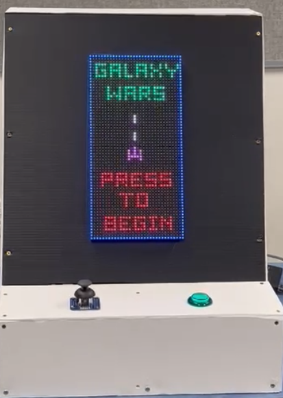
| − | + | [[File:F22-EG-Begin-Screen.png|500px|thumb|left|Start Screen]] | |
| − | + | </td> | |
| − | + | <td> | |
| − | + | </td> | |
| − | + | <td> | |
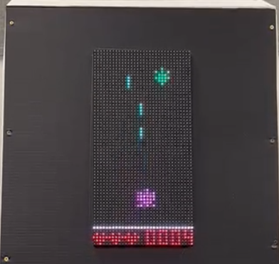
| − | </ | + | [[File:F22-EG-Game-Play.png|500px|thumb|center|Game Play]] |
| + | </td> | ||
| + | <td> | ||
| + | </td> | ||
| + | <td> | ||
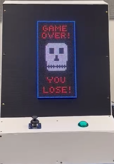
| + | [[File:F22-EG-End-Screen.png|500px|thumb|right|End Screen]] | ||
| + | </td> | ||
| + | </tr> | ||
| + | </table> | ||
| + | </center> | ||
| − | == | + | == '''Abstract''' == |
| − | |||
| − | |||
| − | |||
A horizontal type of space invader game. Players can control the spaceship on the screen composed of an LED matrix in a rectangular shape. The spaceship can shoot horizontally from left to right in order to destroy its enemies. The entire map will flow in the opposite direction of where the spaceship is flying. The speed of the map flow and the number of enemies will increase at higher difficulty levels. The spaceship takes damage from colliding with enemies | A horizontal type of space invader game. Players can control the spaceship on the screen composed of an LED matrix in a rectangular shape. The spaceship can shoot horizontally from left to right in order to destroy its enemies. The entire map will flow in the opposite direction of where the spaceship is flying. The speed of the map flow and the number of enemies will increase at higher difficulty levels. The spaceship takes damage from colliding with enemies | ||
themselves or their bullets. The game will end when the health of the controlled spaceship is depleted. | themselves or their bullets. The game will end when the health of the controlled spaceship is depleted. | ||
| − | == Objectives & Introduction == | + | == '''Objectives & Introduction''' == |
=== Technical Responsibilities === | === Technical Responsibilities === | ||
| Line 24: | Line 30: | ||
{| class="wikitable" style="margin-left: 0px; margin-right: auto;" | {| class="wikitable" style="margin-left: 0px; margin-right: auto;" | ||
|- style="vertical-align: top;" | |- style="vertical-align: top;" | ||
| − | ! colspan="5"| | + | ! colspan="5"| Technical Roles |
|- | |- | ||
! style="text-align: left;" | | ! style="text-align: left;" | | ||
| Line 35: | Line 41: | ||
|- | |- | ||
! style="text-align: left;" | | ! style="text-align: left;" | | ||
| − | * | + | * Joystick Controller Driver |
| − | | | + | | Bruce Jiang |
|- | |- | ||
! style="text-align: left;" | | ! style="text-align: left;" | | ||
* MP3 Decoder | * MP3 Decoder | ||
| − | | | + | | Phil Bloxom |
| + | |- | ||
| + | ! style="text-align: left;" | | ||
| + | * Bluetooth | ||
| + | | Ritu Patil | ||
|- | |- | ||
! style="text-align: left;" | | ! style="text-align: left;" | | ||
* Enclosure | * Enclosure | ||
| − | | | + | | Phil Bloxom |
|- | |- | ||
! style="text-align: left;" | | ! style="text-align: left;" | | ||
| Line 79: | Line 89: | ||
|- | |- | ||
|} | |} | ||
| − | |||
| − | == Schedule == | + | == '''Schedule''' == |
{| class="wikitable" | {| class="wikitable" | ||
| Line 97: | Line 106: | ||
* 10/8/2022 | * 10/8/2022 | ||
| | | | ||
| − | * Read previous projects, gather information and discuss among the group | + | * Read previous projects, gather information and discuss among the group member |
* Create GitLab repository for project | * Create GitLab repository for project | ||
| | | | ||
| Line 133: | Line 142: | ||
| | | | ||
* <span style="color:green">Completed</span> | * <span style="color:green">Completed</span> | ||
| − | * <span style="color: | + | * <span style="color:green">Completed</span> |
|- | |- | ||
! scope="row"| 5 | ! scope="row"| 5 | ||
| Line 143: | Line 152: | ||
* Finalize wiki schedule | * Finalize wiki schedule | ||
* Display objects on screen | * Display objects on screen | ||
| − | * Develop ADC driver for joystick | + | * Develop ADC driver for joystick interfacing control dynamic movement of player spaceship |
| + | * Create screen scenes in 32x64 matrices | ||
| | | | ||
* <span style="color:green">Completed</span> | * <span style="color:green">Completed</span> | ||
* <span style="color:green">Completed</span> | * <span style="color:green">Completed</span> | ||
| − | * <span style="color: | + | * <span style="color:green">Completed</span> |
| + | * <span style="color:green">Completed</span> | ||
|- | |- | ||
! scope="row"| 6 | ! scope="row"| 6 | ||
| Line 157: | Line 168: | ||
* Integration of circuit boards and microcontroller | * Integration of circuit boards and microcontroller | ||
* Develop enemy spaceships game algorithm | * Develop enemy spaceships game algorithm | ||
| − | * | + | * Control dynamic movement of player spaceship. |
| + | * Create MP3 Driver | ||
| | | | ||
| − | * <span style="color: | + | * <span style="color:green">Completed</span> |
| − | * <span style="color: | + | * <span style="color:green">Completed</span> |
| − | * <span style="color: | + | * <span style="color:green">Completed</span> |
| + | * <span style="color:green">Completed</span> | ||
|- | |- | ||
! scope="row"| 7 | ! scope="row"| 7 | ||
| Line 169: | Line 182: | ||
* 11/26/2022 | * 11/26/2022 | ||
| | | | ||
| − | * Integrate game logic | + | * Integrate game logic flow from start to end |
* Develop missile collision and player life algorithm | * Develop missile collision and player life algorithm | ||
* Integrate game sounds with game logic | * Integrate game sounds with game logic | ||
| | | | ||
| − | * <span style="color: | + | * <span style="color:green">Completed</span> |
| − | * <span style="color: | + | * <span style="color:green">Completed</span> |
| − | * <span style="color: | + | * <span style="color:green">Completed</span> |
|- | |- | ||
! scope="row"| 8 | ! scope="row"| 8 | ||
| Line 188: | Line 201: | ||
* Update the wiki page | * Update the wiki page | ||
| | | | ||
| − | * <span style="color: | + | * <span style="color:green">Completed</span> |
| − | * <span style="color: | + | * <span style="color:green">Completed</span> |
| − | * <span style="color: | + | * <span style="color:green">Completed</span> |
|- | |- | ||
! scope="row"| 9 | ! scope="row"| 9 | ||
| Line 201: | Line 214: | ||
* Test pause/play functionality | * Test pause/play functionality | ||
| | | | ||
| − | * <span style="color: | + | * <span style="color:green">Completed</span> |
| − | * <span style="color: | + | * <span style="color:green">Completed</span> |
|- | |- | ||
! scope="row"| 10 | ! scope="row"| 10 | ||
| Line 216: | Line 229: | ||
*Update the wiki page | *Update the wiki page | ||
| | | | ||
| − | * <span style="color: | + | * <span style="color:green">Completed</span> |
| − | * <span style="color: | + | * <span style="color:green">Completed</span> |
| − | * <span style="color: | + | * <span style="color:green">Completed</span> |
| − | * <span style="color: | + | * <span style="color:green">Completed</span> |
| + | |- | ||
| + | |} | ||
| + | |||
| + | == '''Bill of Materials (General Parts)''' == | ||
| + | |||
| + | {| class="wikitable" | ||
| + | |- | ||
| + | ! scope="col" | Part Name | ||
| + | ! scope="col" | Part Model & Source | ||
| + | ! scope="col" | Quantity | ||
| + | ! scope="col" | Cost Per Unit (USD) | ||
| + | |- | ||
| + | | | ||
| + | * Micro-Controller SJ2 Board | ||
| + | | | ||
| + | * SJ2 Board (Purchased from Preet Kang) | ||
| + | | | ||
| + | * 1 | ||
| + | | | ||
| + | * 50.00 | ||
| + | |||
| + | |- | ||
| + | | | ||
| + | * RGB LED Matrix | ||
| + | | | ||
| + | * [https://www.adafruit.com/product/2279?gclid=CjwKCAiA9qKbBhAzEiwAS4yeDYSKVkDu50XPdtCaJTeRJYj02YJb-ABAjVX1WBGGtEr2jHvQRfvufhoCA-QQAvD_BwE 64x32 RGB LED Matrix Panel] | ||
| + | | | ||
| + | * 1 | ||
| + | | | ||
| + | * 44.95 | ||
| + | |||
| + | |- | ||
| + | | | ||
| + | * Power Supply | ||
| + | | | ||
| + | * [https://www.amazon.com/gp/product/B01N2K48HR/ref=ppx_yo_dt_b_search_asin_title?ie=UTF8&psc=1 Universal AC/DC Adapter 3V ~ 12V] | ||
| + | | | ||
| + | * 1 | ||
| + | | | ||
| + | * 15.98 | ||
| + | |- | ||
| + | | | ||
| + | * IDC Socket Male | ||
| + | | | ||
| + | * [https://www.amazon.com/gp/product/B08NB8S42K/ref=ppx_yo_dt_b_asin_title_o00_s00?ie=UTF8&psc=1 IDC Socket Male] | ||
| + | | | ||
| + | * 1 | ||
| + | | | ||
| + | * 0.3 | ||
|- | |- | ||
| + | | | ||
| + | * HC-05 Bluetooth | ||
| + | | | ||
| + | * [https://www.amazon.com/DSD-TECH-HC-05-Pass-through-Communication/dp/B01G9KSAF6/ref=mp_s_a_1_3?adgrpid=57552031393&dplnkId=fa65647f-fc92-41f1-a50c-4ac9bfec67f3&gclid=Cj0KCQiAmaibBhCAARIsAKUlaKSJHxYgLW7SP5wMd94uqHWtJ7IlGGyw2zsTxZFHoU3KT5dqm0vMzJcaAjntEALw_wcB&hvadid=609115864507&hvdev=m&hvlocphy=9032166&hvnetw=g&hvqmt=e&hvrand=14587583350658056883&hvtargid=kwd-298511473808&hydadcr=20105_13388467&keywords=hc+05+bluetooth+module&nodl=1&qid=1667939624&sr=8-3 HC-05 Bluetooth] | ||
| + | | | ||
| + | * 2 | ||
| + | | | ||
| + | * 10 | ||
| + | |- | ||
| + | | | ||
| + | * Analog Joystick | ||
| + | | | ||
| + | * [https://www.adafruit.com/product/512 Analog 2 Axis x-y Thumb Joystick] | ||
| + | | | ||
| + | * 1 | ||
| + | | | ||
| + | * 6 | ||
|} | |} | ||
| − | + | == '''Overall Design''' == | |
| − | + | === Hardware Design === | |
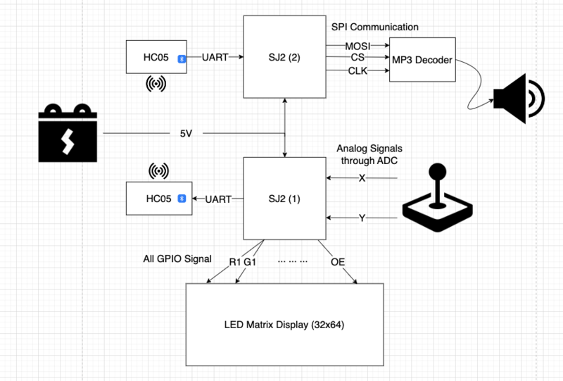
| − | + | [[File:F22_EG_Overall_Design_Diagram_11_18_2022.png|800px|thumb|center|LED Matrix Rear]] | |
| − | |||
| − | == | + | === Hardware Interface === |
| − | + | * LED Matrix Display: 13 GPIO channel on SJ2 (1) | |
| + | * Joystick connection: 2 ADC channel on SJ2 (1) | ||
| + | * Bluetooth sender connection: 1 set UART, RX and TX on SJ2 (1) | ||
| + | * Bluetooth receiver connection: 1 set UART, RX and TX on SJ2 (2) | ||
| + | * MP3 Decoder connection: SPI communication, MOSI, CS, SCK, on SJ2 (2) | ||
| + | * Speaker connection: AUX cord | ||
| + | === Software Design === | ||
| + | * LED Matrix: | ||
| + | **1. Initialized LED matrix connected pins to board IOs. | ||
| + | **2. Designed matrix driver for screen display by reading an matrix. | ||
| + | |||
| + | * Joystick: | ||
| + | **1. Initialized 2 ADC channels for taking the x reading and y reading from joystick. | ||
| + | **2. Decoded voltage readings into joystick movement commands. | ||
| + | |||
| + | * Buttons: | ||
| + | **1. Initialized several gpio for taking binary command from button pressed. | ||
| + | **2. Enabled interrupts for each botton pressed. | ||
| + | |||
| + | * Mp3 Player: | ||
| + | **1. Initialize using UART3. | ||
| + | **2. Set device with selected sd card and volume. | ||
| + | |||
| + | === Implementation === | ||
| + | * LED Matrix driver functions: | ||
| + | **1. display_update: reload matrix display for refreshing the changes from the backend matrix. | ||
| + | **2. display_clear: erase all matrix values, and sets them to zeros. | ||
| + | **3. overwrite_pattern_to_screen: overite a given pattern onto the existing matrix | ||
| + | **4. append_pattern_to_screen: append a given pattern onto the existing matrix | ||
| + | **5. clear_pattern_on_screen: clear the pattern from screen by giving the pattern's current location and width and height. | ||
| + | |||
| + | * Joystick driver: | ||
| + | **1. joystick_running: run ADC capture on joystick continuesly to monitor user inputs. | ||
| + | |||
| + | * Buttons driver: | ||
| + | **1. Green button: starts a game, shots a missile, and start the game all over. | ||
| + | |||
| + | * Mp3 Player: | ||
| + | **1. Play a song. | ||
| + | **2. Play a song in single cycle. | ||
| + | **3. Play a song from a folder. | ||
| + | **4. Pause on play. | ||
| + | **5. Resume playback. | ||
| + | |||
| + | == '''RGB LED Matrix''' == | ||
=== Hardware Design === | === Hardware Design === | ||
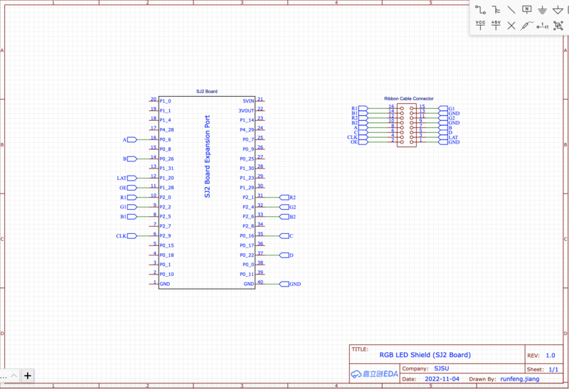
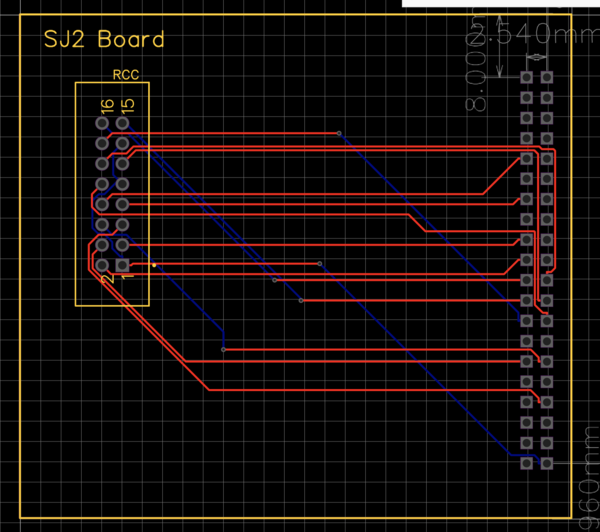
| − | + | Below are symbol and footprint for custom component-part in EasyEDA tool. These parts would be used in future PCB design. | |
| + | [[File:F22_Embedded_Gamers_LED_Matrix_Schematic.png|800px|thumb|left|LED Matrix and SJ2 Board Connections Schematics]] | ||
| + | [[File:F22_Embedded_Gamers_LED_Matrix_PCB.png|600px|thumb|center|LED Matrix and SJ2 Board Connections PCB]] | ||
| + | <br><br> | ||
=== Hardware Interface === | === Hardware Interface === | ||
| − | + | The 32x64 LED matrix is from Adafruit, with [https://learn.adafruit.com/32x16-32x32-rgb-led-matrix/overview user mannual]. It is composed of two upper and lower sectional LED pannels. Each pannel has R, G, B led channels and A, B, C, and D row control registers. Addtionally, column shift is controlled by Latch bit, clock is controled by CLK, and OE turns LED off when switching rows. | |
| + | |||
| + | <center> | ||
| + | <table> | ||
| + | <tr> | ||
| + | <td> | ||
| + | Connectivity Table LED Matrix to Sj2 Board: | ||
| + | {| class="wikitable" | ||
| + | |- | ||
| + | ! align="center"|RGB LED Matrix | ||
| + | ! align="center"|Pin Description | ||
| + | ! align="center"|SJ2 Board | ||
| + | |- | ||
| + | | scope="row" align="center"|R1 | ||
| + | | scope="row" align="center"|GPIO | ||
| + | | scope="row" align="center"|P2_0 | ||
| + | |- | ||
| + | | scope="row" align="center"|G1 | ||
| + | | scope="row" align="center"|GPIO | ||
| + | | scope="row" align="center"|P2_2 | ||
| + | |- | ||
| + | | scope="row" align="center"|B1 | ||
| + | | scope="row" align="center"|GPIO | ||
| + | | scope="row" align="center"|P2_5 | ||
| + | |- | ||
| + | | scope="row" align="center"|R2 | ||
| + | | scope="row" align="center"|GPIO | ||
| + | | scope="row" align="center"|P2_1 | ||
| + | |- | ||
| + | | scope="row" align="center"|G2 | ||
| + | | scope="row" align="center"|GPIO | ||
| + | | scope="row" align="center"|P2_4 | ||
| + | |- | ||
| + | | scope="row" align="center"|B2 | ||
| + | | scope="row" align="center"|GPIO | ||
| + | | scope="row" align="center"|P2_6 | ||
| + | |- | ||
| + | | scope="row" align="center"|A | ||
| + | | scope="row" align="center"|GPIO | ||
| + | | scope="row" align="center"|P0_6 | ||
| + | |- | ||
| + | | scope="row" align="center"|B | ||
| + | | scope="row" align="center"|GPIO | ||
| + | | scope="row" align="center"|P0_26 | ||
| + | |- | ||
| + | | scope="row" align="center"|C | ||
| + | | scope="row" align="center"|GPIO | ||
| + | | scope="row" align="center"|P0_16 | ||
| + | |- | ||
| + | | scope="row" align="center"|D | ||
| + | | scope="row" align="center"|GPIO | ||
| + | | scope="row" align="center"|P0_22 | ||
| + | |- | ||
| + | | scope="row" align="center"|CLK | ||
| + | | scope="row" align="center"|GPIO | ||
| + | | scope="row" align="center"|P2_9 | ||
| + | |- | ||
| + | | scope="row" align="center"|LAT | ||
| + | | scope="row" align="center"|GPIO | ||
| + | | scope="row" align="center"|P1_20 | ||
| + | |- | ||
| + | | scope="row" align="center"|OE | ||
| + | | scope="row" align="center"|GPIO | ||
| + | | scope="row" align="center"|P1_28 | ||
| + | |- | ||
| + | | scope="row" align="center"|VCC | ||
| + | | scope="row" align="center"|5VIN | ||
| + | | scope="row" align="center"|External Power Supply | ||
| + | |- | ||
| + | | scope="row" align="center"|GND | ||
| + | | scope="row" align="center"|GND | ||
| + | | scope="row" align="center"|On Board | ||
| + | |- | ||
| + | |} | ||
| + | </td> | ||
| + | <td> | ||
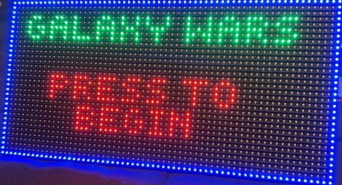
| + | [[File:F22_EG_WelcomeScreen.jpg|500px|thumb|left|LED Matrix Front]] | ||
| + | </td> | ||
| + | <td> | ||
| + | </td> | ||
| + | <td> | ||
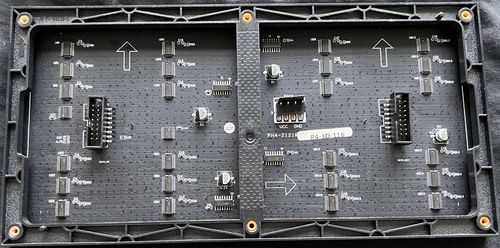
| + | [[File:F22_EG_LED_Rear.jpg|500px|thumb|right|LED Matrix Rear]] | ||
| + | </td> | ||
| + | </tr> | ||
| + | </table> | ||
| + | </center> | ||
| + | |||
| + | === Software Design === | ||
| + | LED matrix io and driver is developed for communication between boards and LED matrix. IO driver consists of pin inialization by using gpio.h for each rgb channels, row selection register, CLK, LAT, and OE pins. By using "led_matrix_io.h" developers can using public function led_matrix_io_init and other basic controller functions. <br> | ||
| + | For LED matrix driver, it is based on the previous IO driver to provide LED screen update, clean, init, and draw functionalities. | ||
| + | |||
| + | === Implementation === | ||
| + | Rtos Tasks: | ||
| + | *Updating Display: for display to continuously updating screen, a task is assigned for running the display_update function from the driver every 500 milliseconds. | ||
| + | |||
| + | == '''Joystick and Buttons''' == | ||
| + | |||
| + | === Hardware Interface and Connections=== | ||
| + | |||
| + | <center> | ||
| + | <table> | ||
| + | <tr> | ||
| + | <td> | ||
| + | Connectivity Table LED Matrix to Sj2 Board: | ||
| + | {| class="wikitable" | ||
| + | |- | ||
| + | ! align="center"|Joystick | ||
| + | ! align="center"|Pin Description | ||
| + | ! align="center"|SJ2 Board | ||
| + | |- | ||
| + | | scope="row" align="center"|Vcc | ||
| + | | scope="row" align="center"|Voltage | ||
| + | | scope="row" align="center"|+3.3V | ||
| + | |- | ||
| + | | scope="row" align="center"|Xout | ||
| + | | scope="row" align="center"|Analog X Channel | ||
| + | | scope="row" align="center"|P0_25 | ||
| + | |- | ||
| + | | scope="row" align="center"|Yout | ||
| + | | scope="row" align="center"|Analog Y Channel | ||
| + | | scope="row" align="center"|P1_30 | ||
| + | |- | ||
| + | | scope="row" align="center"|Button | ||
| + | | scope="row" align="center"|GPIO | ||
| + | | scope="row" align="center"|P1_14 | ||
| + | |- | ||
| + | | scope="row" align="center"|GND | ||
| + | | scope="row" align="center"|GND | ||
| + | | scope="row" align="center"|GND | ||
| + | |- | ||
| + | |} | ||
| + | </td> | ||
| + | <td> | ||
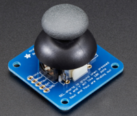
| + | [[File:F22_EG_Analog_Joystick.png|200px|thumb|right|[https://www.adafruit.com/product/512?gclid=Cj0KCQiA99ybBhD9ARIsALvZavVtFSwQejbcb1pB1_3x5x2FsKY89WqOIHKEsKq_jxfXcSg3rY-AsWQaAlnREALw_wcB Analog Joystick ]]] | ||
| + | </td> | ||
| + | <td> | ||
| + | </td> | ||
| + | </tr> | ||
| + | </table> | ||
| + | </center> | ||
| + | |||
| + | === Software Design === | ||
| + | Joystick with voltage input produces two analog channels of outputs from the x and y axises of the joystick. Designed a driver to convert these two analog outputs and convert them into digital signals, then decoded as user movment such as move up, move down, move left, move right, move right up, move right down, move left up, and move left down. | ||
| + | |||
| + | === Implementation === | ||
| + | Rtos Tasks: | ||
| + | *JoyStick Running: Keep recieving two channels of analog signals and decode them into agent moves corresponding to right, left, up, down, right up, right left, left up, and left down. | ||
| + | |||
| + | == '''Mp3 Decoder''' == | ||
| + | |||
| + | === Hardware Interface and Connections=== | ||
| + | |||
| + | <center> | ||
| + | <table> | ||
| + | <tr> | ||
| + | <td> | ||
| + | Connectivity Table Mp3 Player to Sj2 Board: | ||
| + | {| class="wikitable" | ||
| + | |- | ||
| + | ! align="center"|Mp3 Decoder | ||
| + | ! align="center"|Pin Description | ||
| + | ! align="center"|SJ2 Board | ||
| + | |- | ||
| + | | scope="row" align="center"|Vcc | ||
| + | | scope="row" align="center"|Voltage | ||
| + | | scope="row" align="center"|+3.3V | ||
| + | |- | ||
| + | | scope="row" align="center"|Rx | ||
| + | | scope="row" align="center"|UART3 | ||
| + | | scope="row" align="center"|P4_28 | ||
| + | |- | ||
| + | | scope="row" align="center"|Tx | ||
| + | | scope="row" align="center"|UART3 | ||
| + | | scope="row" align="center"|P4_29 | ||
| + | |- | ||
| + | | scope="row" align="center"|GND | ||
| + | | scope="row" align="center"|GND | ||
| + | | scope="row" align="center"|GND | ||
| + | |- | ||
| + | |} | ||
| + | </td> | ||
| + | <td> | ||
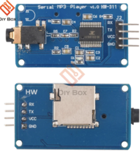
| + | [[File:F22_EG_mp3_encoder.png|200px|thumb|right|[https://www.aliexpress.us/item/3256803093988130.html?pdp_npi=2%40dis%21USD%21US%20%241.67%21%240.99%21%21%21%21%21%40210312ea16702784601312016e68e7%2112000024999658900%21btf&_t=pvid%3Ac6785b98-0d8f-441e-8be9-feb74c7b1693&afTraceInfo=1005003280302882__pc__pcBridgePPC__xxxxxx__1670278460&spm=a2g0o.ppclist.product.mainProduct&gatewayAdapt=glo2usa&_randl_shipto=US Mp3 Player]]] | ||
| + | </td> | ||
| + | <td> | ||
| + | </td> | ||
| + | </tr> | ||
| + | </table> | ||
| + | </center> | ||
=== Software Design === | === Software Design === | ||
| − | + | Mp3 player driver was created. It initialized UART3 and configured IO connections of RX and Tx. To send command for adust volume, play songs by number, play songs by folder name, and set play songs in cycle, please find the user manual here: [https://usermanual.wiki/Pdf/Serial20MP320Player20v10120Manual.2117229468/view mp3 player user manual] | |
=== Implementation === | === Implementation === | ||
| − | + | Public Tasks: | |
| + | *Initialize device: Select the sd card which has songs on the player | ||
| + | *Cycle play mode: play a song in single cycle | ||
| + | *Pause a song | ||
| + | *Resume playback | ||
| + | |||
| + | == '''Game Logic''' == | ||
| + | |||
| + | === Game States === | ||
| + | *1. Start Up | ||
| + | *2. Game Running | ||
| + | *3. Game Over | ||
| + | |||
| + | === Player Task=== | ||
| + | Game state: start up | ||
| + | *1. Display start up screen once per starting | ||
| + | *2. Reset game parameters | ||
| + | |||
| + | Game state: game running | ||
| + | *1. Display player and health bar on screen | ||
| + | *2. Capture and move player location by joystick signals | ||
| + | *3. Check health and switch to game over state when player's health reaches zero | ||
| + | *4. Check collision in collision mutex | ||
| + | |||
| + | Game state: game over | ||
| + | *1. Display game over screen | ||
| − | == | + | === Enemy Task=== |
| − | + | Game state: game running | |
| − | + | *1. Spawn enemy according to a timer for different game levels | |
| + | *2. Checking enemy collision in collision mutex | ||
| + | *3. Remove collided enemy within a list of enemy objects | ||
| − | + | === Button Task=== | |
| + | Game state: start up | ||
| + | *1. Play the back ground music in single cycle | ||
| + | *2. If the green button is pressed, advanced to game running stage | ||
| − | === | + | Game state: game running |
| − | + | *1. Play the back groud music in single cycle | |
| + | *2. If the green button is pressed, generate missile on screen and play a laser sound | ||
| + | |||
| + | Game state: game over | ||
| + | *1. Play the game over music in single cycle | ||
| + | *2. If the green button is pressed, return the state over all back to start up | ||
| + | |||
| + | === Missile Task === | ||
| + | Game state: game running | ||
| + | *1. Check missile collision with enemy, player, and the boundary of the screen | ||
| + | *2. Append missiles in array | ||
| + | |||
| + | === Score Task === | ||
| + | Game state: game running | ||
| + | *1. If a missile hit an enemy, score plus two | ||
| + | *2. If an enemy hit the bottom white line, which is our home base, score minus two | ||
| + | *3. According to the number of score, increase enemy speed and spawn rate by a fix proportion | ||
| + | |||
| + | == '''Testing & Technical Challenges''' == | ||
| + | Most of the challenges for our project are bluetooth paring and game logic. For bluetooth to work between two boards, the configuration driver was wrote from scratch, which enable the device, and select paring bluetooth's physical address. For game logic, the problems are making sure the collision happened between mutiple objects with different moving speed. | ||
| + | |||
| + | === Bug/Issue Name === | ||
| + | {| class="wikitable" | ||
| + | |- | ||
| + | ! scope="col" | Bug Number | ||
| + | ! scope="col" | Description | ||
| + | ! scope="col" | Solution | ||
| + | |- | ||
| + | | | ||
| + | * 1 | ||
| + | | | ||
| + | * Two bluetooth device are not talking to each others automatically. | ||
| + | | | ||
| + | * Used SJ2 board to configure the bluetooth through UART with AT commands | ||
| + | |- | ||
| + | | | ||
| + | * 2 | ||
| + | | | ||
| + | * When a missile hit an enemy on the screen, sometimes, the missile will disapear first but not the enemy, and sometimes, the other way around. | ||
| + | | | ||
| + | * Used mutex and pair locks to make sure when collision happened, only erase both objects by receiving both acknowledgments from enemy and missile. | ||
| + | |- | ||
| + | | | ||
| + | * 3 | ||
| + | | | ||
| + | * Button debounce issue. | ||
| + | | | ||
| + | * The button interrupt from ISR was not performing ideally. By using Preet's suggestion, a simple task of reading the button input solved this problem. | ||
| + | |- | ||
| + | | | ||
| + | * 4 | ||
| + | | | ||
| + | * Player animation conflicts with moving missile. | ||
| + | | | ||
| + | * Disabled missile generation while before playing the animation. | ||
| + | |} | ||
| − | == Conclusion == | + | == '''Conclusion''' == |
| − | + | Coding a complicated Atari game on a microcontroller is a bit more complicated than we thought before starting. We went through writing our own base line driver for controlling other electronic components. Then, figured out FreeRTOS task API to move each character pixels on the led matrix. During development, we faced all different kind of issues such as button debounce, priority conflicts, parallel logic in sequential programming, and etc. In the end, we truly learned that nothing is for granted, as an embedded engineers we have to do everthing ourselves. This project can be further improved on score system and joystick movements. | |
=== Project Video === | === Project Video === | ||
| − | + | https://youtu.be/QRE9pQ7dBBg | |
=== Project Source Code === | === Project Source Code === | ||
| + | https://gitlab.com/runfeng.jiang/cmpe-244-space-invader-game/-/tree/main | ||
| − | == References == | + | == '''References''' == |
=== Acknowledgement === | === Acknowledgement === | ||
| − | + | Special thanks to Mr. Preet Kang for his lessons and detailed-documentation website on microcontrollers. | |
=== References Used === | === References Used === | ||
| − | + | *1. Mp3 user manual: https://usermanual.wiki/Pdf/Serial20MP320Player20v10120Manual.2117229468/view | |
| + | *2. LPC40xx_FreeRtos Github: https://gitlab.com/sjtwo-c-dev/sjtwo-c | ||
| + | *3. Adafruit LED matrix user manual: https://learn.adafruit.com/32x16-32x32-rgb-led-matrix/ | ||
=== Appendix === | === Appendix === | ||
| − | + | *1. LPC40xx_FreeRtos Github: https://gitlab.com/sjtwo-c-dev/sjtwo-c | |
| + | *2. FreeRTOS: https://www.freertos.org/a00116.html | ||
Latest revision as of 23:03, 14 December 2022
Contents
Guardians of the Galaxy
Abstract
A horizontal type of space invader game. Players can control the spaceship on the screen composed of an LED matrix in a rectangular shape. The spaceship can shoot horizontally from left to right in order to destroy its enemies. The entire map will flow in the opposite direction of where the spaceship is flying. The speed of the map flow and the number of enemies will increase at higher difficulty levels. The spaceship takes damage from colliding with enemies themselves or their bullets. The game will end when the health of the controlled spaceship is depleted.
Objectives & Introduction
Technical Responsibilities
| Technical Roles | ||||
|---|---|---|---|---|
|
Bruce Jiang | |||
|
Bruce Jiang | |||
|
Bruce Jiang | |||
|
Phil Bloxom | |||
|
Ritu Patil | |||
|
Phil Bloxom | |||
|
Bruce Jiang & Phil Bloxom | |||
Administrative Responsibilities
| Administrative Roles | ||||
|---|---|---|---|---|
|
Ritu Patil | |||
|
Bruce Jiang | |||
|
Phil Bloxom | |||
|
Bruce Jiang | |||
|
Ritu Patil | |||
Schedule
| Week# | Start Date | End Date | Task | Status |
|---|---|---|---|---|
| 1 |
|
|
|
|
| 2 |
|
|
|
|
| 3 |
|
|
|
|
| 4 |
|
|
|
|
| 5 |
|
|
|
|
| 6 |
|
|
|
|
| 7 |
|
|
|
|
| 8 |
|
|
|
|
| 9 |
|
|
|
|
| 10 |
|
|
|
|
Bill of Materials (General Parts)
| Part Name | Part Model & Source | Quantity | Cost Per Unit (USD) |
|---|---|---|---|
|
|
|
|
|
|
| |
|
|
| |
|
|
| |
|
|
| |
|
|
|
Overall Design
Hardware Design
Hardware Interface
- LED Matrix Display: 13 GPIO channel on SJ2 (1)
- Joystick connection: 2 ADC channel on SJ2 (1)
- Bluetooth sender connection: 1 set UART, RX and TX on SJ2 (1)
- Bluetooth receiver connection: 1 set UART, RX and TX on SJ2 (2)
- MP3 Decoder connection: SPI communication, MOSI, CS, SCK, on SJ2 (2)
- Speaker connection: AUX cord
Software Design
- LED Matrix:
- 1. Initialized LED matrix connected pins to board IOs.
- 2. Designed matrix driver for screen display by reading an matrix.
- Joystick:
- 1. Initialized 2 ADC channels for taking the x reading and y reading from joystick.
- 2. Decoded voltage readings into joystick movement commands.
- Buttons:
- 1. Initialized several gpio for taking binary command from button pressed.
- 2. Enabled interrupts for each botton pressed.
- Mp3 Player:
- 1. Initialize using UART3.
- 2. Set device with selected sd card and volume.
Implementation
- LED Matrix driver functions:
- 1. display_update: reload matrix display for refreshing the changes from the backend matrix.
- 2. display_clear: erase all matrix values, and sets them to zeros.
- 3. overwrite_pattern_to_screen: overite a given pattern onto the existing matrix
- 4. append_pattern_to_screen: append a given pattern onto the existing matrix
- 5. clear_pattern_on_screen: clear the pattern from screen by giving the pattern's current location and width and height.
- Joystick driver:
- 1. joystick_running: run ADC capture on joystick continuesly to monitor user inputs.
- Buttons driver:
- 1. Green button: starts a game, shots a missile, and start the game all over.
- Mp3 Player:
- 1. Play a song.
- 2. Play a song in single cycle.
- 3. Play a song from a folder.
- 4. Pause on play.
- 5. Resume playback.
RGB LED Matrix
Hardware Design
Below are symbol and footprint for custom component-part in EasyEDA tool. These parts would be used in future PCB design.
Hardware Interface
The 32x64 LED matrix is from Adafruit, with user mannual. It is composed of two upper and lower sectional LED pannels. Each pannel has R, G, B led channels and A, B, C, and D row control registers. Addtionally, column shift is controlled by Latch bit, clock is controled by CLK, and OE turns LED off when switching rows.
|
Connectivity Table LED Matrix to Sj2 Board:
|
Software Design
LED matrix io and driver is developed for communication between boards and LED matrix. IO driver consists of pin inialization by using gpio.h for each rgb channels, row selection register, CLK, LAT, and OE pins. By using "led_matrix_io.h" developers can using public function led_matrix_io_init and other basic controller functions.
For LED matrix driver, it is based on the previous IO driver to provide LED screen update, clean, init, and draw functionalities.
Implementation
Rtos Tasks:
- Updating Display: for display to continuously updating screen, a task is assigned for running the display_update function from the driver every 500 milliseconds.
Joystick and Buttons
Hardware Interface and Connections
|
Connectivity Table LED Matrix to Sj2 Board:
|
Software Design
Joystick with voltage input produces two analog channels of outputs from the x and y axises of the joystick. Designed a driver to convert these two analog outputs and convert them into digital signals, then decoded as user movment such as move up, move down, move left, move right, move right up, move right down, move left up, and move left down.
Implementation
Rtos Tasks:
- JoyStick Running: Keep recieving two channels of analog signals and decode them into agent moves corresponding to right, left, up, down, right up, right left, left up, and left down.
Mp3 Decoder
Hardware Interface and Connections
|
Connectivity Table Mp3 Player to Sj2 Board:
|
Software Design
Mp3 player driver was created. It initialized UART3 and configured IO connections of RX and Tx. To send command for adust volume, play songs by number, play songs by folder name, and set play songs in cycle, please find the user manual here: mp3 player user manual
Implementation
Public Tasks:
- Initialize device: Select the sd card which has songs on the player
- Cycle play mode: play a song in single cycle
- Pause a song
- Resume playback
Game Logic
Game States
- 1. Start Up
- 2. Game Running
- 3. Game Over
Player Task
Game state: start up
- 1. Display start up screen once per starting
- 2. Reset game parameters
Game state: game running
- 1. Display player and health bar on screen
- 2. Capture and move player location by joystick signals
- 3. Check health and switch to game over state when player's health reaches zero
- 4. Check collision in collision mutex
Game state: game over
- 1. Display game over screen
Enemy Task
Game state: game running
- 1. Spawn enemy according to a timer for different game levels
- 2. Checking enemy collision in collision mutex
- 3. Remove collided enemy within a list of enemy objects
Button Task
Game state: start up
- 1. Play the back ground music in single cycle
- 2. If the green button is pressed, advanced to game running stage
Game state: game running
- 1. Play the back groud music in single cycle
- 2. If the green button is pressed, generate missile on screen and play a laser sound
Game state: game over
- 1. Play the game over music in single cycle
- 2. If the green button is pressed, return the state over all back to start up
Missile Task
Game state: game running
- 1. Check missile collision with enemy, player, and the boundary of the screen
- 2. Append missiles in array
Score Task
Game state: game running
- 1. If a missile hit an enemy, score plus two
- 2. If an enemy hit the bottom white line, which is our home base, score minus two
- 3. According to the number of score, increase enemy speed and spawn rate by a fix proportion
Testing & Technical Challenges
Most of the challenges for our project are bluetooth paring and game logic. For bluetooth to work between two boards, the configuration driver was wrote from scratch, which enable the device, and select paring bluetooth's physical address. For game logic, the problems are making sure the collision happened between mutiple objects with different moving speed.
Bug/Issue Name
| Bug Number | Description | Solution |
|---|---|---|
|
|
|
|
|
|
|
|
|
|
|
|
Conclusion
Coding a complicated Atari game on a microcontroller is a bit more complicated than we thought before starting. We went through writing our own base line driver for controlling other electronic components. Then, figured out FreeRTOS task API to move each character pixels on the led matrix. During development, we faced all different kind of issues such as button debounce, priority conflicts, parallel logic in sequential programming, and etc. In the end, we truly learned that nothing is for granted, as an embedded engineers we have to do everthing ourselves. This project can be further improved on score system and joystick movements.
Project Video
Project Source Code
https://gitlab.com/runfeng.jiang/cmpe-244-space-invader-game/-/tree/main
References
Acknowledgement
Special thanks to Mr. Preet Kang for his lessons and detailed-documentation website on microcontrollers.
References Used
- 1. Mp3 user manual: https://usermanual.wiki/Pdf/Serial20MP320Player20v10120Manual.2117229468/view
- 2. LPC40xx_FreeRtos Github: https://gitlab.com/sjtwo-c-dev/sjtwo-c
- 3. Adafruit LED matrix user manual: https://learn.adafruit.com/32x16-32x32-rgb-led-matrix/
Appendix
- 1. LPC40xx_FreeRtos Github: https://gitlab.com/sjtwo-c-dev/sjtwo-c
- 2. FreeRTOS: https://www.freertos.org/a00116.html
