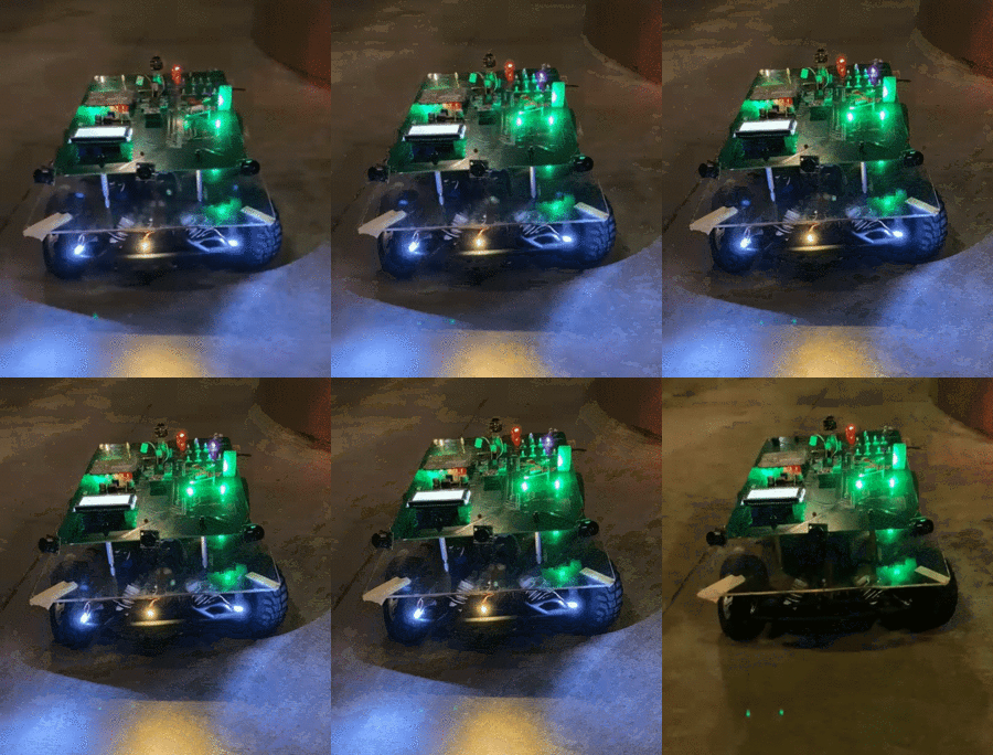
Difference between revisions of "S21: Roadster"
Proj user12 (talk | contribs) (→Obstacle Avoidance Logic) |
Proj user12 (talk | contribs) (→Schedule) |
||
| (228 intermediate revisions by 3 users not shown) | |||
| Line 1: | Line 1: | ||
| + | [[File:gifroadster.gif|right|thumb|300px| Roadster]] | ||
| + | |||
== Roadster == | == Roadster == | ||
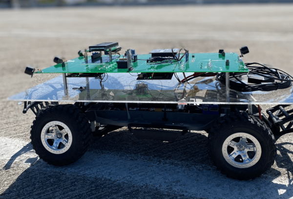
| + | [[File:Side view Roadster.png|left|thumb|600px| Roadster]] | ||
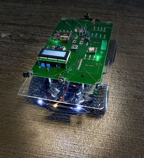
| + | [[File:Roadsterportrait.jpeg|right|thumb|500px| Roadster]] | ||
| + | <BR/> | ||
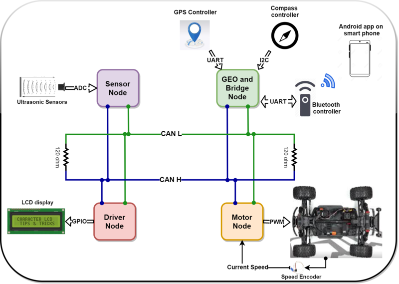
[[File:System_design_roadster.png|center|800px| System Design]] | [[File:System_design_roadster.png|center|800px| System Design]] | ||
| Line 8: | Line 13: | ||
=== Introduction === | === Introduction === | ||
| − | The project was divided into | + | The project was divided into 5 modules: |
| − | * Sensor Node | + | * Sensor Node- Detecting obstacles in the vicinity of the car to avoid hitting the obstacle and maneuver around the same. |
| − | * Geo Node | + | * Geo and Bridge Node- Provide heading for car to reach destination. Communicate over blue tooth with mobile application. Battery state. |
| − | * Driver Node | + | * Driver Node- Manipulate turn angles and forward/reverse speed based on the inputs from Sensor and Geo nodes |
| − | * | + | * Motor Node- PID control logic to attain the said speed/direction desired by driver node. |
| − | * Android Application | + | * Android Application- Dashboard for real time data from car. Send instruction such as destination, way points and start/stop. |
=== Team Members & Responsibilities === | === Team Members & Responsibilities === | ||
| − | |||
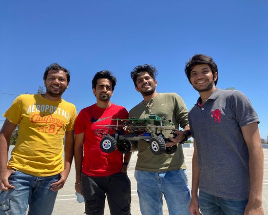
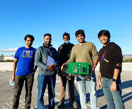
| − | Tejas Pidwalkar | + | [[File:Team Picture 2.jpeg|thumb|550px|caption|left|Team Picture]] |
| + | [[File:Team picture 1.jpeg|thumb|550px|caption|center|Team Picture with '''Preet''']] | ||
| + | |||
| + | |||
| + | '''Roadster GitLab - [https://gitlab.com/nimit.patel/roadster/-/tree/master Gitlab]''' | ||
| + | |||
| + | '''Tejas Pidwalkar [https://www.linkedin.com/in/tejaspidkalwar/ LinkedIn]''' | ||
*Sensor Node | *Sensor Node | ||
*Driver Node | *Driver Node | ||
| − | Nimit Patel | + | *Wiki Page Update |
| − | *Geo Node | + | *Integration Testing |
| − | Tirth Pandya | + | '''Nimit Patel [https://www.linkedin.com/in/nimit393/ LinkedIn]''' |
| + | *Geo And Bridge Node | ||
| + | *Wiki Page Update | ||
| + | *Integration Testing | ||
| + | '''Tirth Pandya [https://www.linkedin.com/in/tirthpandya/ LinkedIn]''' | ||
*Motor Node | *Motor Node | ||
*PCB design | *PCB design | ||
| − | Srikar Reddy | + | *Wiki Page Update |
| + | *Integration Testing | ||
| + | '''Srikar Reddy [https://www.linkedin.com/in/srikar-narapureddy/ LinkedIn]''' | ||
*Android Application | *Android Application | ||
| − | Sourab Gupta | + | *Wiki Page Update |
| + | '''Sourab Gupta [https://www.linkedin.com/in/sourab-gupta-52b18553/ LinkedIn]''' | ||
*Driver Node | *Driver Node | ||
| − | + | *Wiki Page Update | |
| − | + | *Integration Testing | |
| − | |||
| − | |||
| − | |||
| − | |||
| − | |||
| − | |||
| − | |||
| − | |||
| − | |||
| − | |||
| − | |||
| − | |||
| − | |||
| − | |||
| − | |||
| − | |||
| − | |||
| − | |||
| − | |||
| − | |||
| − | |||
| − | |||
| − | |||
| − | |||
| − | |||
| − | * Testing | ||
| − | |||
| − | |||
<HR> | <HR> | ||
| Line 184: | Line 173: | ||
| | | | ||
* <font color = 'maroon'>03/24</font> | * <font color = 'maroon'>03/24</font> | ||
| − | * | + | * 03/24 |
* 03/28 | * 03/28 | ||
* 03/30 | * 03/30 | ||
| Line 190: | Line 179: | ||
| | | | ||
*<font color = "green"> Completed | *<font color = "green"> Completed | ||
| − | *<font color = " | + | *<font color = "green"> Completed |
*<font color = "green"> Completed | *<font color = "green"> Completed | ||
*<font color = "green"> Completed | *<font color = "green"> Completed | ||
| Line 222: | Line 211: | ||
* <font color = 'maroon>04/05</font> | * <font color = 'maroon>04/05</font> | ||
* 04/01 | * 04/01 | ||
| − | * | + | * 04/01 |
| − | * | + | * 04/01 |
* <font color = 'maroon'>04/04</font> | * <font color = 'maroon'>04/04</font> | ||
* 04/04 | * 04/04 | ||
| Line 229: | Line 218: | ||
*<font color = "green"> Completed | *<font color = "green"> Completed | ||
*<font color = "green"> Completed | *<font color = "green"> Completed | ||
| − | *<font color = " | + | *<font color = "green"> Completed |
| − | *<font color = " | + | *<font color = "green"> Completed |
*<font color = "green"> Completed | *<font color = "green"> Completed | ||
*<font color = "green"> Completed | *<font color = "green"> Completed | ||
| Line 253: | Line 242: | ||
* '''Collective Test 2''':<font color = "DarkGreen">''' Drive the car to a hardcoded GPS destination'''</font color> | * '''Collective Test 2''':<font color = "DarkGreen">''' Drive the car to a hardcoded GPS destination'''</font color> | ||
| | | | ||
| − | * | + | * 04/08 |
| − | * | + | * 04/08 |
| − | * | + | * 04/08 |
| − | * | + | * 04/08 |
| | | | ||
| − | *<font color = " | + | *<font color = "green"> Completed |
| − | *<font color = " | + | *<font color = "green"> Completed |
| − | *<font color = " | + | *<font color = "green"> Completed |
| − | *<font color = " | + | *<font color = "green"> Completed |
|- | |- | ||
! scope="row"| 7 | ! scope="row"| 7 | ||
| Line 281: | Line 270: | ||
* '''Collective Test 3''':<font color = "DarkGreen">''' Test the car driving with navigation data from the Android app'''</font color> | * '''Collective Test 3''':<font color = "DarkGreen">''' Test the car driving with navigation data from the Android app'''</font color> | ||
| | | | ||
| − | * | + | * 04/15 |
| − | * | + | * 04/18 |
| − | * | + | * 04/16 |
| − | * | + | * 04/18 |
| | | | ||
| − | *<font color = " | + | *<font color = "green"> Completed |
| − | *<font color = " | + | *<font color = "green"> Completed |
| − | *<font color = " | + | *<font color = "green"> Completed |
| − | *<font color = " | + | *<font color = "green"> Completed |
|- | |- | ||
! scope="row"| 8 | ! scope="row"| 8 | ||
| Line 310: | Line 299: | ||
* Test and improve the RC car performance based on the changes | * Test and improve the RC car performance based on the changes | ||
| | | | ||
| + | * 04/25 | ||
* | * | ||
| − | * | + | * 04/25 |
| − | * | + | * 04/25 |
| − | |||
| | | | ||
| − | *<font color = " | + | *<font color = "green"> Completed |
| − | *<font color = " | + | *<font color = "red"> Incomplete |
| − | *<font color = " | + | *<font color = "green"> Completed |
| − | *<font color = " | + | *<font color = "green"> Completed |
|- | |- | ||
! scope="row"| 9 | ! scope="row"| 9 | ||
| Line 339: | Line 328: | ||
* '''Collective Test 4:'''<font color = "DarkGreen">''' Test car on various terrains and slopes'''</font color> | * '''Collective Test 4:'''<font color = "DarkGreen">''' Test car on various terrains and slopes'''</font color> | ||
| | | | ||
| − | * | + | * 04/30 |
| − | * | + | * 04/30 |
| − | * | + | * 04/30 |
| − | * | + | * 05/02 |
| | | | ||
| − | *<font color = " | + | *<font color = "green"> Completed |
| − | *<font color = " | + | *<font color = "green"> Completed |
| − | *<font color = " | + | *<font color = "green"> Completed |
| − | *<font color = " | + | *<font color = "green"> Completed |
|- | |- | ||
! scope="row"| 10 | ! scope="row"| 10 | ||
| Line 367: | Line 356: | ||
* '''Collective Test 5:'''<font color = "DarkGreen">''' Test the Prototype 1 with the aim of sending the car to return Preet's PCAN Dongle'''</font color> | * '''Collective Test 5:'''<font color = "DarkGreen">''' Test the Prototype 1 with the aim of sending the car to return Preet's PCAN Dongle'''</font color> | ||
| | | | ||
| − | * | + | * 05/07 |
| − | * | + | * 05/07 |
| − | * | + | * 05/07 |
| − | * | + | * 05/09 |
| | | | ||
| − | *<font color = " | + | *<font color = "green"> Completed |
| − | *<font color = " | + | *<font color = "green"> Completed |
| − | *<font color = " | + | *<font color = "green"> Completed |
| − | *<font color = " | + | *<font color = "brown"> Deferred |
|- | |- | ||
! scope="row"| 11 | ! scope="row"| 11 | ||
| Line 396: | Line 385: | ||
* '''Collective Test 6:'''<font color = "DarkGreen">''' Have the final version of the project tested with all the functionalities'''</font color> | * '''Collective Test 6:'''<font color = "DarkGreen">''' Have the final version of the project tested with all the functionalities'''</font color> | ||
| | | | ||
| − | * | + | * 05/16 |
| − | * | + | * 05/16 |
| − | * | + | * 05/16 |
| − | * | + | * 05/16 |
| | | | ||
| − | *<font color = " | + | *<font color = "green"> Completed |
| − | *<font color = " | + | *<font color = "green"> Completed |
| − | *<font color = " | + | *<font color = "green"> Completed |
| − | *<font color = " | + | *<font color = "green"> Completed |
|} | |} | ||
| Line 439: | Line 428: | ||
! scope="row"| 4 | ! scope="row"| 4 | ||
| GPS and Antenna | | GPS and Antenna | ||
| − | | | + | | Adafruit[https://www.amazon.com/Adafruit-Ultimate-GPS-Breakout-External/dp/B00I6LZW4O/ref=sr_1_7?dchild=1&keywords=adafruit+gps&qid=1622071143&sr=8-7] |
| 1 | | 1 | ||
| $60.00 | | $60.00 | ||
| + | |- | ||
| + | ! scope="row"| 5 | ||
| + | | HC05 bluetooth RF Transreceiver | ||
| + | | HiLetgo[https://www.amazon.com/HiLetgo-Bluetooth-Transceiver-Integrated-Communication/dp/B07VL725T8/] | ||
| + | | 1 | ||
| + | | $12.59 | ||
| + | |- | ||
| + | ! scope="row"| 6 | ||
| + | | Triple-axis Accelerometer | ||
| + | | Adafruit[https://www.adafruit.com/product/1120] | ||
| + | | 1 | ||
| + | | $21.40 | ||
| + | |- | ||
| + | ! scope="row"| 7 | ||
| + | | Traxxas RPM Sensor | ||
| + | | Traxxas[https://www.amazon.com/Traxxas-6520-RPM-Sensor-long/dp/B006IRXEZM] | ||
| + | | 1 | ||
| + | | $12 | ||
| + | |- | ||
| + | ! scope="row"| 8 | ||
| + | | Discrete Electronic Components | ||
| + | | Generic[http://www.excesssolutions.com/] | ||
| + | | 1 | ||
| + | | $28.75 | ||
| + | |- | ||
| + | ! scope="row"| 9 | ||
| + | | Buck-Boost Voltage Regulator | ||
| + | | Generic[https://www.amazon.com/Adjustable-Converter-Automatic-Voltage-Regulator/dp/B07NTXSJHB/] | ||
| + | | 1 | ||
| + | | $11.99 | ||
| + | |- | ||
| + | ! scope="row"| 10 | ||
| + | | Traxxas Telemetry Trigger magnet & holder | ||
| + | | Traxxas[https://www.amazon.com/Traxxas-Telemetry-Trigger-Magnet-Holder/dp/B00864A3T0/] | ||
| + | | 1 | ||
| + | | $6.35 | ||
| + | |- | ||
| + | ! scope="row"| 11 | ||
| + | | Acrylic Sheet | ||
| + | | Tap Plastic | ||
| + | | 1 | ||
| + | | $12 | ||
| + | |- | ||
| + | ! scope="row"| 12 | ||
| + | | Battery | ||
| + | | Amazon[https://www.amazon.com/dp/B07LGZGG7T?ref=ppx_pop_mob_ap_share] | ||
| + | | 1 | ||
| + | | $26.99 | ||
| + | |- | ||
| + | ! scope="row"| 13 | ||
| + | | Traxxas Battery and Charger | ||
| + | | Amazon[https://www.amazon.com/dp/B074FXXP5J/ref=cm_sw_r_wa_api_glt_fabc_TQCR9J50NFX7VYE33PWB?_encoding=UTF8&psc=1] | ||
| + | | 1 | ||
| + | | $55.94 | ||
|- | |- | ||
|} | |} | ||
| Line 449: | Line 492: | ||
== Printed Circuit Board == | == Printed Circuit Board == | ||
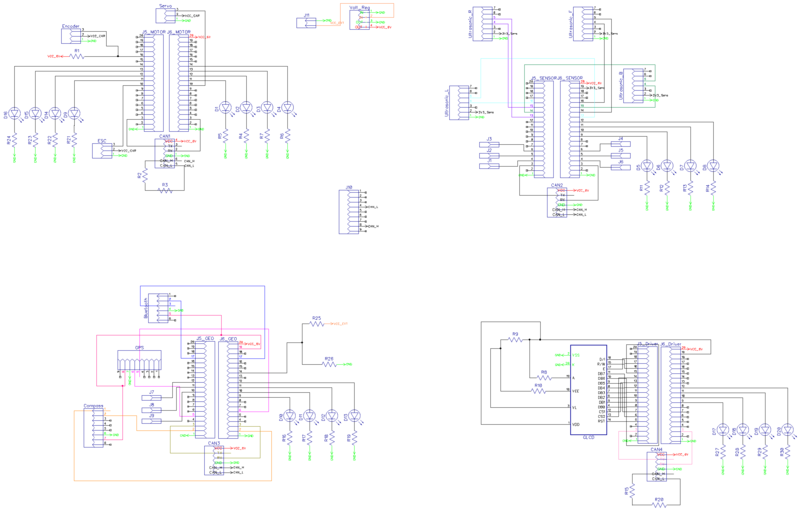
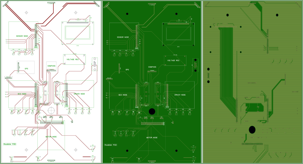
| − | < | + | <h4>PCB Schematic</h4> |
| − | < | + | [[File:RoadsterSchematic.png|center|thumb|800px| Roadster Schematic]] |
| + | <h4>PCB Design</h4> | ||
| + | [[File:RoadsterPCB.png|center | 1200px| Roadster PCB]] | ||
| − | |||
| − | |||
== CAN Communication == | == CAN Communication == | ||
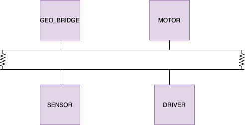
| − | + | We use controller area network to broadcast data between the 4 nodes. All nodes are connected to each other through a physically conventional two wire bus. The wires are a twisted pair with 120 Ω resistors at each ends of the bus. 1s and 0s are transmitted as CAN High(0V difference) and Can Low(2v difference). | |
| + | A CAN frame has the following contents: | ||
| + | * Data Length Code (4bits) | ||
| + | * Remote Transmission Request. | ||
| + | * ID extend bit. | ||
| + | * Message ID (11 bit or 29 bit) | ||
| + | * Data bytes( depends on DLC) | ||
| + | * CRC | ||
| + | |||
| + | |||
| + | '''Arbitration''': No two nodes will transmit at the same time because if arbitration. A lower Message-ID has a Higher priority on the CAN bus since 0 is the dominant bit. | ||
| + | |||
| + | '''Bit Stuffing''': CAN bus stuffs extra bits when a long chain of multiple 1's or 0's occur to improve CAN integrity. | ||
| + | |||
| + | {| class="wikitable" | ||
| + | |- | ||
| + | ! scope="col"| Sr. No | ||
| + | ! scope="col"| Message ID | ||
| + | ! scope="col"| Message function | ||
| + | ! scope="col"| Receivers | ||
| + | |- | ||
| + | |- | ||
| + | |- | ||
| + | |- | ||
| + | ! colspan="4"| Driver Controller | ||
| + | |- | ||
| + | |- | ||
| + | |1 | ||
| + | |300 | ||
| + | |speed and steering direction for the motor. | ||
| + | |Motor | ||
| + | |- | ||
| + | |2 | ||
| + | |310 | ||
| + | |Destination reached | ||
| + | |Sensor | ||
| + | |- | ||
| + | |- | ||
| + | ! colspan="4"| Sensor Controller | ||
| + | |- | ||
| + | |- | ||
| + | |1 | ||
| + | |200 | ||
| + | |Sensor sonars from front, back, left ,right sensor | ||
| + | |Driver | ||
| + | |- | ||
| + | |- | ||
| + | ! colspan="4"| Motor Controller | ||
| + | |- | ||
| + | |- | ||
| + | |8 | ||
| + | |700 | ||
| + | |motor speed, motor direction | ||
| + | |Driver | ||
| + | |- | ||
| + | |- | ||
| + | ! colspan="4"| Geo and Bridge Controller | ||
| + | |- | ||
| + | |- | ||
| + | |1 | ||
| + | |400 | ||
| + | |Bearing, Heading and Distance | ||
| + | |Driver | ||
| + | |- | ||
| + | |- | ||
| + | ! colspan="4"| Debug messages | ||
| + | |- | ||
| + | |- | ||
| + | |1 | ||
| + | |851 | ||
| + | |Driver Debug | ||
| + | |SENSOR,MOTOR,GEO_AND_BRIDGE | ||
| + | |- | ||
| + | |- | ||
| + | |1 | ||
| + | |811 | ||
| + | |Motor Debug | ||
| + | |SENSOR,MOTOR,GEO_AND_BRIDGE | ||
| + | |- | ||
| + | |- | ||
| + | |1 | ||
| + | |801 | ||
| + | |Sensor Debug | ||
| + | |SENSOR,MOTOR,GEO_AND_BRIDGE | ||
| + | |- | ||
| + | |- | ||
| + | |} | ||
| + | |||
=== Hardware Design === | === Hardware Design === | ||
| − | < | + | |
| + | [[File:roadstercan.png|center|500px|thumb|CAN Bus Design]] | ||
| + | |||
| + | <br/> | ||
=== DBC File === | === DBC File === | ||
| − | < | + | |
| − | < | + | <syntaxhighlight lang=c> |
| + | VERSION "" | ||
| + | |||
| + | NS_ : | ||
| + | BA_ | ||
| + | BA_DEF_ | ||
| + | BA_DEF_DEF_ | ||
| + | BA_DEF_DEF_REL_ | ||
| + | BA_DEF_REL_ | ||
| + | BA_DEF_SGTYPE_ | ||
| + | BA_REL_ | ||
| + | BA_SGTYPE_ | ||
| + | BO_TX_BU_ | ||
| + | BU_BO_REL_ | ||
| + | BU_EV_REL_ | ||
| + | BU_SG_REL_ | ||
| + | CAT_ | ||
| + | CAT_DEF_ | ||
| + | CM_ | ||
| + | ENVVAR_DATA_ | ||
| + | EV_DATA_ | ||
| + | FILTER | ||
| + | NS_DESC_ | ||
| + | SGTYPE_ | ||
| + | SGTYPE_VAL_ | ||
| + | SG_MUL_VAL_ | ||
| + | SIGTYPE_VALTYPE_ | ||
| + | SIG_GROUP_ | ||
| + | SIG_TYPE_REF_ | ||
| + | SIG_VALTYPE_ | ||
| + | VAL_ | ||
| + | VAL_TABLE_ | ||
| + | |||
| + | BS_: | ||
| + | |||
| + | BU_: DRIVER MOTOR SENSOR GEO_AND_BRIDGE DEBUG | ||
| + | |||
| + | BO_ 200 SENSOR_SONARS: 5 SENSOR | ||
| + | SG_ SENSOR_SONARS_left : 0|10@1+ (1,0) [0|800] "cm" DRIVER | ||
| + | SG_ SENSOR_SONARS_right : 10|10@1+ (1,0) [0|0] "cm" DRIVER | ||
| + | SG_ SENSOR_SONARS_middle : 20|10@1+ (1,0) [0|0] "cm" DRIVER | ||
| + | SG_ SENSOR_SONARS_rear : 30|10@1+ (1,0) [0|0] "cm" DRIVER | ||
| + | |||
| + | BO_ 300 DRIVER_TO_MOTOR: 2 DRIVER | ||
| + | SG_ MOTOR_speed : 0|8@1+ (0.1,-12.5) [-12.5|12.5] "m/s" MOTOR | ||
| + | SG_ MOTOR_direction : 8|7@1+ (1,-45) [-45|45] "degree" MOTOR | ||
| + | |||
| + | BO_ 310 DRIVER_BROADCAST: 1 DRIVER | ||
| + | SG_ DEST_reached : 0|8@1+ (1,0) [0|0] "flag" SENSOR | ||
| + | |||
| + | BO_ 400 GEO_CONTROLLER_COMPASS: 6 GEO_AND_BRIDGE | ||
| + | SG_ HEADING : 0|12@1+ (1,0) [0|359] "Degrees" DRIVER | ||
| + | SG_ BEARING : 12|12@1+ (1,0) [0|359] "Degrees" DRIVER | ||
| + | SG_ DISTANCE : 24|17@1+ (0.01,0) [0|0] "Meters" DRIVER | ||
| + | |||
| + | BO_ 401 GEO_CONTROLLER_COMPASS_DEBUG: 9 GEO_AND_BRIDGE | ||
| + | SG_ WAYPOINT_COUNT : 0|8@1+ (1,0) [0|16] "" DEBUG | ||
| + | SG_ STATUS : 8|8@1+ (1,0) [0|359] "Degrees" DEBUG | ||
| + | SG_ DISTANCE_TO_WAYPOINT : 16|12@1+ (0.01,0) [0|0] "Meters" DEBUG | ||
| + | SG_ HEADING_TO_WAYPOINT : 28|12@1+ (1,0) [0|359] "Degrees" DEBUG | ||
| + | SG_ BEARING_TO_WAYPOINT : 40|12@1+ (1,0) [0|359] "Degrees" DEBUG | ||
| + | SG_ HEADING_RAW : 52|12@1+ (1,0) [0|359] "Degrees" DEBUG | ||
| + | SG_ WAYPOINT_CURRENT : 64|8@1+ (1,0) [0|16] "" DEBUG | ||
| + | |||
| + | BO_ 700 MOTOR_TO_DRIVER: 8 MOTOR | ||
| + | SG_ MOTOR_speed:0|8@1+ (0.1,-12.5) [-12.5|12.5] "m/s" DRIVER | ||
| + | SG_ MOTOR_direction : 8|7@1+ (1,-45) [-45|45] "degree" DRIVER | ||
| + | |||
| + | BO_ 851 DRIVER_DEBUG_DATA: 1 DEBUG | ||
| + | SG_ forwardDrivingState:0|2@1+ (1,0) [0|0] "" SENSOR,MOTOR,GEO_AND_BRIDGE | ||
| + | SG_ reverseDrivingState: 2|2@1+ (1,0) [0|0] "" SENSOR,MOTOR,GEO_AND_BRIDGE | ||
| + | SG_ isRightSteeringPossible:4|2@1+ (1,0) [0|0] "" SENSOR,MOTOR,GEO_AND_BRIDGE | ||
| + | SG_ isLeftSteeringPossible:6|2@1+ (1,0) [0|0] "" SENSOR,MOTOR,GEO_AND_BRIDGE | ||
| + | |||
| + | BO_ 801 SENSOR_DEBUG_DATA: 8 DEBUG | ||
| + | SG_ LEFT_sensor_raw:0|16@1+ (1,0) [0|0] "cm" SENSOR,MOTOR,GEO_AND_BRIDGE | ||
| + | SG_ RIGHT_sensor_raw: 16|16@1+ (1,0) [0|0] "cm" SENSOR,MOTOR,GEO_AND_BRIDGE | ||
| + | SG_ FRONT_sensor_raw: 32|16@1+ (1,0) [0|0] "cm" SENSOR,MOTOR,GEO_AND_BRIDGE | ||
| + | SG_ REAR_sensor_raw: 48|16@1+ (1,0) [0|0] "cm" SENSOR,MOTOR,GEO_AND_BRIDGE | ||
| + | |||
| + | BO_ 811 MOTOR_DEBUG_DATA: 8 DEBUG | ||
| + | SG_ MOTOR_rps_value:0|32@1+ (1,0) [0|0] "rps value" SENSOR,DRIVER,GEO_AND_BRIDGE | ||
| + | SG_ MOTOR_pwm_value:32|8@1+ (0.01,0) [0|0] "dc motor pwm value" SENSOR,DRIVER,GEO_AND_BRIDGE | ||
| + | |||
| + | BO_ 1000 DRIVER_HEARTBEAT: 1 DRIVER | ||
| + | SG_ DRIVER_HEARTBEAT_cmd : 0|8@1+ (1,0) [0|0] "" SENSOR,MOTOR,GEO_AND_BRIDGE | ||
| + | |||
| + | BO_ 1100 MOTOR_HEARTBEAT: 1 DRIVER | ||
| + | SG_ MOTOR_HEARTBEAT_cmd : 0|8@1+ (1,0) [0|0] "" SENSOR,DRIVER,GEO_AND_BRIDGE | ||
| + | |||
| + | BO_ 1200 SENSOR_HEARTBEAT: 1 DRIVER | ||
| + | SG_ SENSOR_HEARTBEAT_cmd : 0|8@1+ (1,0) [0|0] "" MOTOR,DRIVER,GEO_AND_BRIDGE | ||
| + | |||
| + | BO_ 1300 GEO_HEARTBEAT: 1 DRIVER | ||
| + | SG_ GEO_HEARTBEAT_cmd : 0|8@1+ (1,0) [0|0] "" SENSOR,MOTOR,DRIVER | ||
| + | |||
| + | CM_ BU_ DRIVER "The driver controller driving the car"; | ||
| + | CM_ BU_ MOTOR "The motor controller of the car"; | ||
| + | CM_ BU_ SENSOR "The sensor controller of the car"; | ||
| + | CM_ BO_ 100 "Sync message used to synchronize the controllers"; | ||
| + | CM_ SG_ 100 DRIVER_HEARTBEAT_cmd "Heartbeat command from the driver"; | ||
| + | |||
| + | BA_DEF_ "BusType" STRING ; | ||
| + | BA_DEF_ BO_ "GenMsgCycleTime" INT 0 0; | ||
| + | BA_DEF_ SG_ "FieldType" STRING ; | ||
| + | |||
| + | BA_DEF_DEF_ "BusType" "CAN"; | ||
| + | BA_DEF_DEF_ "FieldType" ""; | ||
| + | BA_DEF_DEF_ "GenMsgCycleTime" 0; | ||
| + | |||
| + | BA_ "GenMsgCycleTime" BO_ 100 1000; | ||
| + | BA_ "GenMsgCycleTime" BO_ 200 50; | ||
| + | BA_ "FieldType" SG_ 100 DRIVER_HEARTBEAT_cmd "DRIVER_HEARTBEAT_cmd"; | ||
| + | |||
| + | VAL_ 100 DRIVER_HEARTBEAT_cmd 2 "DRIVER_HEARTBEAT_cmd_REBOOT" 1 "DRIVER_HEARTBEAT_cmd_SYNC" 0 "DRIVER_HEARTBEAT_cmd_NOOP" ; | ||
| + | </syntaxhighlight> | ||
<HR> | <HR> | ||
<BR/> | <BR/> | ||
| + | |||
== Sensor ECU == | == Sensor ECU == | ||
<Picture and link to Gitlab> | <Picture and link to Gitlab> | ||
| + | Gitlab link to Sensor Node Firmware: https://gitlab.com/nimit.patel/roadster/-/tree/Main/Sensor_Node | ||
| + | |||
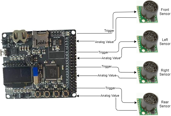
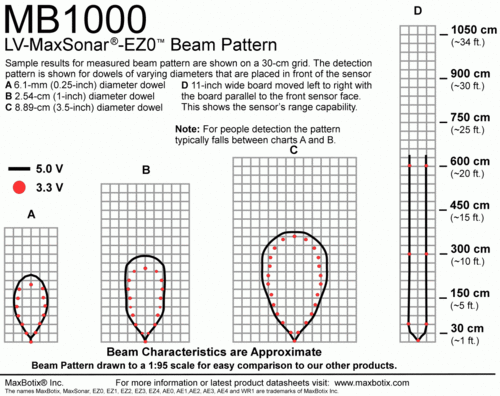
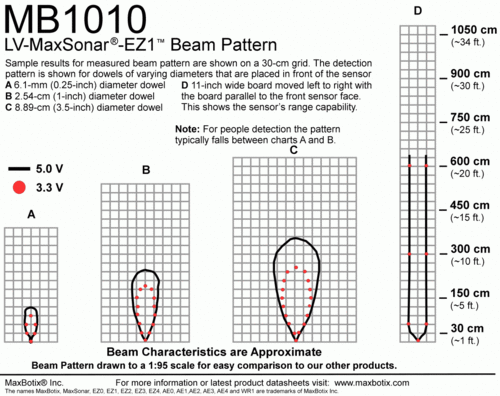
| + | The sensor controller node is responsible for interfacing with Ultrasonic sensors to know obstacles’ distance from the vehicle. We have used MaxBotix 1010 LV-EZ1 sensors for the right and left positions and MaxBotix 1000 LV-EZ0 sensor in the middle front position (To have a wider beam range of obstacle detection in blind spots). | ||
| + | |||
| + | [[File:Sensor_Node.png|center|800px|thumb|Sensor Controller Diagram]] | ||
| + | |||
| + | Below is the beam pattern for both sensors. | ||
| + | |||
| + | [[File:Beam_Pattern_MB1000_EZ0.gif|left|500px|thumb|Beam Pattern MaxBotix MB1000 EZ0]] | ||
| + | [[File:Beam_Pattern_MB1010_EZ1.gif|center|500px|thumb|Beam Pattern MaxBotix MB1010 EZ1]] | ||
| + | |||
=== Hardware Design === | === Hardware Design === | ||
| − | === Software Design === | + | ==== Sensor Controller Schematic ==== |
| − | < | + | |
| + | |||
| + | [[File:SensorSch.png|center|800px|thumb|Sensor Controller Node Schematic]] | ||
| + | |||
| + | |||
| + | ==== Board Pin Connections ==== | ||
| + | |||
| + | Sensors are interfaced with combination of GPIO, ADC Pins on SJTWo board. Below is the descriptive pin layout: | ||
| + | |||
| + | {| class="wikitable" style="text-align: center; width: 400px; height: 200px;" | ||
| + | |+ Sensors pin layout | ||
| + | |- | ||
| + | ! Sr. No. | ||
| + | ! SJTwo board Pin | ||
| + | ! Maxbotix sensor Pin | ||
| + | ! Function | ||
| + | |- | ||
| + | ! 1 | ||
| + | | ADC2-P0.25 || AN(Front sensor) || ADC input from front sensor | ||
| + | |- | ||
| + | ! 2 | ||
| + | | ADC3-P0.26 || AN(Rear Sensor) || ADC input from rear sensor | ||
| + | |- | ||
| + | ! 3 | ||
| + | | ADC4-P1.30 || AN(Left Sensor) || ADC input from left sensor | ||
| + | |- | ||
| + | ! 4 | ||
| + | | ADC5-P1.31 || AN(Right Sensor) || ADC input from right sensor | ||
| + | |- | ||
| + | ! 5 | ||
| + | | GPIO-P0.6 || RX(Left Sensor) || Trigger for left sensor | ||
| + | |- | ||
| + | ! 6 | ||
| + | | GPIO-P0.7 || RX(Front Sensor) || Trigger for front sensor | ||
| + | |- | ||
| + | ! 7 | ||
| + | | GPIO-P0.8 || RX(Right Sensor) || Trigger for right sensor | ||
| + | |- | ||
| + | ! 8 | ||
| + | | GPIO-P0.9 || RX(Rear Sensor) || Trigger for rear sensor | ||
| + | |} | ||
| + | |||
| + | === <font color="0000FF">Software Design </font>=== | ||
| + | |||
| + | The sensor node mainly does two activity viz. 1) Read sensor values, 2) Transmit obstacle distance over CAN bus. Both of these activities happen in a 20Hz periodic callback. | ||
| + | |||
| + | 1. Read Sensor Values | ||
| + | |||
| + | * Sensors are mounted at four locations as mentioned below diagram. To read these sensor values, we initialized and configured 4 sensors using 4 ADCs viz ADC2, ADC3, ADC4, and ADC5. Considering the front 3 sensors' close proximity and possible beam interference, we decided to range extreme front sensors at a time and the middle front next in sequence while in a 20 Hz loop. And the rear sensor is triggered regularly. All the sensor values are digitally converted in the range of 0 to 4096 (12 bit ADC). These values are converted to distance format in centimeter unit using formula '''conv_val = (raw_val * 0.3182) - 0.3959'''. | ||
| + | [[File:Sensor_placement.png|center|400px|thumb|Sensors Placement location]] | ||
| + | |||
| + | * Now, to avoid frequent noise pulses, we used a median filter. We created an array of 10 elements for each sensor and maintained a write index to track the current update position. Thus, all read values have been updated in the buffer which acts as a circular buffer as we start overwriting from the start index. | ||
| + | |||
| + | 2. Transmit obstacle distance over CAN bus: | ||
| + | |||
| + | * Sensor node is responsible for broadcasting all four sensor values in terms of distance in centimeter over CAN bus. To broadcast filtered values, it first sorts the existing values in the respective allocated sensor buffer. Then it takes the mean of five median values. It does the same thing for all four sensors. Finally, it transmits those values over CAN bus. Below flow chart gives the detailed flow of code at a high level. | ||
| + | |||
| + | [[File:Sensor_Node_flow_chart.png|center|600px|thumb|Sensor Node Controller Flow Chart]] | ||
| + | |||
| + | === <font color="0000FF">Technical Challenges </font>=== | ||
| + | |||
| + | ==== Neighboring Sensor Interference: ==== | ||
| + | * As explained above, we have mounted three ultrasonic sensors in the front, and those were configured to range in continuous mode, in which sensors were continuously measuring distance by transmitting beam. Out of 3, the middle sensor is of type with wider beam to detect blind spots ahead. | ||
| + | * Most of the time, we observed that the obstacle in the middle sensor range used also gets detected by the left/right sensor, which disturbs driving logic. This used to happen due to sensor beam interference among three sensors. | ||
| + | * To solve this problem, we decided to trigger sensor beams in such time intervals that they won’t interfere with neighboring ones. We used the Rx pin of the sensor to trigger ranging and scheduled to trigger left and right sensor at one time and middle sensor next time. This sequence helped us avoid interference altogether. | ||
| − | === | + | ==== Frequent noisy measurements: ==== |
| + | * While reading the obstacle distance, it used to change suddenly to some random value, and that used to disturb driving logic. To get noise-free readings from sensors, we implemented a median filter. All the read values from sensors have been collected in the respective buffer of 10 elements. While sending obstacle distance on CAN bus, the median filter sort the buffer and takes an average of 5 median values. This way, it helped us to remove almost all noisy values. | ||
| − | |||
<HR> | <HR> | ||
<BR/> | <BR/> | ||
| + | |||
== Motor ECU == | == Motor ECU == | ||
| − | + | [[File:MotorSch.png|center|800px|thumb| Motor Node Schematic]] | |
=== Hardware Design === | === Hardware Design === | ||
| + | [[File:XL5esc.png|300px|thumb|left|Traxass ESC XL5]] | ||
| + | [[File:Servotrx.jpg|300px|right|thumb|Traxass Servo Motor]] | ||
| + | [[File:Rpmsens.jpg|300px|center|thumb|Traxass RPM Sensor]] | ||
| + | <BR/> | ||
| + | |||
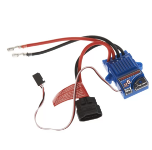
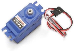
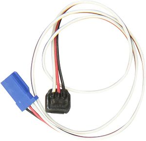
| + | The motor node(SJ-2) interfaces primarily interfaces with: | ||
| + | * Traxass Motor ESC over PWM | ||
| + | * Traxass RPM Sensor over GPIO Interrupt | ||
| + | * Traxass Servo Motor over PWM | ||
| + | |||
| + | All these three components have 3 pins each. The functionalities of these pins are mentioned in the table below. | ||
| + | |||
| + | {| class="wikitable" | ||
| + | |- | ||
| + | ! scope="col"| Module | ||
| + | ! scope="col"| Black | ||
| + | ! scope="col"| Red | ||
| + | ! scope="col"| White | ||
| + | |- | ||
| + | ! scope="row"| ESC | ||
| + | | Ground | ||
| + | | Vout : 6 V | ||
| + | | PWM Input | ||
| + | |- | ||
| + | ! scope="row"| Servo | ||
| + | | Ground | ||
| + | | Vin : 6 V | ||
| + | | PWM Input | ||
| + | |- | ||
| + | ! scope="row"| RPM Sensor | ||
| + | | Ground | ||
| + | | Vin : 6 V | ||
| + | | Pulse Output | ||
| + | |} | ||
=== Software Design === | === Software Design === | ||
| − | + | ||
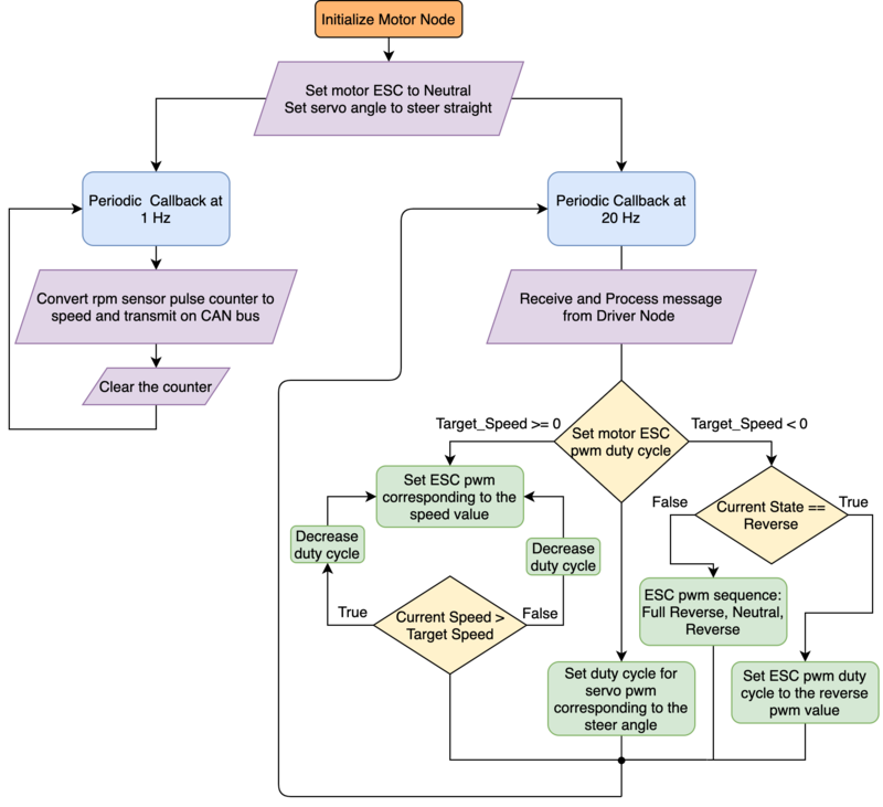
| + | The motor node acts based on the speed and direction received over CAN bus from the Driver Node. The positive speed values are treated as forward motion and the negative speed values are considered to be the reverse motion of the RC car. | ||
| + | |||
| + | The steering angles are divided into 5-degree segments and the motor node sends the pre-defined pwm duty cycle of the particular segment to the servo motor depending on the angle value received from the driver node. | ||
| + | |||
| + | [[File:Flowchartmotor.png|800px|thumb|center|Motor Node - Software Flowchart]] | ||
=== Technical Challenges === | === Technical Challenges === | ||
| − | + | * Firstly, the Traxxas motor ESC and other Traxass parts are members of the Traxxas Hobby Parts family, and they are not intended for development purposes. This is why there are no technical specification documents or any program/development guides available. One needs to test the motor ESC by feeding the PWM duty cycles in various sequences at various duty cycle percentages. We used the Remote control to reproduce some scenarios where the ESC was behaving unexpectedly. | |
| − | + | * The ESC configuration changes to the Lipo battery state if the Lipo battery is used. If one switches back to the NiMH battery, then the ESC starts flashing the led in a green-red repeated sequence, and the ESC power button stops working. In this scenario, there is a calibration process that can save your boat and can make the ESC function normally again. Follow this procedure : [https://www.youtube.com/watch?v=1br9_h1OsV8 ESC Calibration] | |
| + | *Another challenge with the motor node program development is that you cannot rely on unit testing. Whoever works on the motor node, should make sure that the sequence of the duty cycles being fed to the ESC produces the expected results on the motor as well. The forward-reverse transitioning and the speed controlling both can be a bit tricky. Also, the hard brake logic can take a while to get working properly. | ||
| + | * Some useful reference values for the ESC are : 15% -> Neutral; 15.8%-> Minimum forward speed, 10%->Full reverse speed. | ||
<HR> | <HR> | ||
<BR/> | <BR/> | ||
| − | |||
| − | + | == Geographical And Bridge Controller == | |
| + | |||
| + | ''[https://gitlab.com/nimit.patel/roadster/-/merge_requests/5 Repository link for Geo Controller]'' | ||
=== Hardware Design === | === Hardware Design === | ||
| + | [[File:GeoSch.png|650px|thumb|center|Geo Node Schematic]] | ||
| + | <BR/> | ||
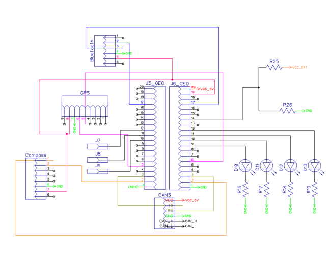
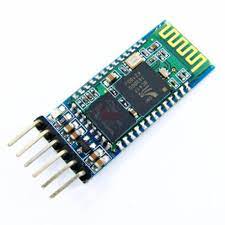
| + | [[File:Hc05.jpeg|400px|thumb|left|Bluetooth Trans-receiver]] | ||
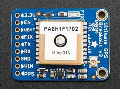
| + | [[File:GPS.jpg|400px|thumb|right|GPS Module]] | ||
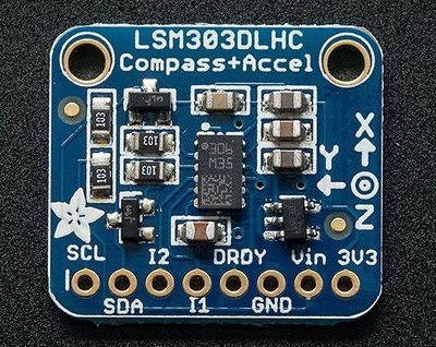
| + | [[File:compass_roadster.jpg|400px|thumb|center|3 Axis Magnetometer (eCompass)]] | ||
| + | <BR/> | ||
| + | [[File:Votlage Divider.jpg|400px|thumb|right|Battery Monitoring]] | ||
| + | |||
| + | <BR/> | ||
| + | |||
| + | |||
| + | The SJ2 board communicates with: | ||
| + | * Bluettoth transreceiver over UART | ||
| + | * LSM303DLHC over I2C | ||
| + | * GPS model over UART | ||
| + | * Battery monitoring | ||
| + | |||
| + | Considering the orientation of the car changes as it travel along the land, tilt compensation logic for heading calculation using the magnetometer is a must for accurate measurement. Without the tilt compensation algorithm which uses the onboard accelorometer, the heading computation can have error up to 60 degrees, which has the potential to send the car off course. | ||
| + | <BR/> | ||
| + | <BR/> | ||
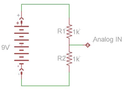
| + | For battery monitoring, the values for the voltage divider should be chosen such that the full range of the onboard ADC can be efficiently used. Depending one the cell type of the battery, the discharge curve can be use to map the charge state corresponding to voltage level. This method has its flaws and sophisticated techniques involving Coulomb count yields far better results, however, the technique discussed above suffices the needs of our project. Charge state of battery transmitted over Mobile app, greatly facilitates the charging schedule while testing and final demo day. | ||
| + | |||
| + | <BR/> | ||
| + | <BR/> | ||
=== Software Design === | === Software Design === | ||
| − | The GEO controller is divided into | + | The periodic scheduler for Geo Controller Node does the following functionalities: |
| + | * In 10Hz periodic callback: | ||
| + | ** gps__update() : Fetch GPS data from GPS controller. | ||
| + | ** geo_compass__periodic_send() : Reads the Magnetometer and accelerometer values from Compass controller and convert those to current heading data. | ||
| + | * In 100Hz periodic callback: | ||
| + | ** bluetooth__run_once() : Send specified data to android application via Bluetooth. | ||
| + | |||
| + | The GEO controller is divided into 5 parts. | ||
| + | |||
| + | *The current location of the car is determined using the GPS. | ||
| + | |||
| + | *The current magnetic heading of car is determined using the on board compass. | ||
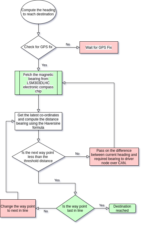
| − | The current location | + | *The way point calculation determines the nearest way point continuously by computing the distance using Haversine formula and current location using GPS. |
| − | The | + | *The heading is also computed using the Haversine formula and the difference between the actual and required is sent over the CAN bus for heading correction. |
| − | + | *Alternatively, once the car is within the threshold distance, next way point is selected and the car heads to the next way point. | |
| − | |||
| − | + | [[File:Geo logic.png|800px|thumb|center|Heading computation from geographical (Geo) controller]] | |
=== Technical Challenges === | === Technical Challenges === | ||
| − | + | * The GPS module sends data at 9600 baud rate, updating the data every one second. The data update rate needs to be updated to 10Hz for fast maneuvering and course correction of the car. If the update frequency is updated, the data sent over the UART is higher than it can handle in 10Hz periodic function. Hence, only GPGGA messages should be enabled to extract the required data and reduce the time spent in parsing the incoming string. NEMA (PMTK) messages should be correctly configured on the module for desired functioning. | |
| − | + | * Heading calculation without the tilt compensation logic using the onboard accelorometer of LSM303 is in accurate. Reading accelorometer values requires and offset of 0x80 to the byte addressing of the accelorometer read. Magnetometer need no such offset. This is weird, considering both the I2C devices reside on the same physical chip. | |
| + | *Using data type as float as opposed to double, utilizes the onboard FPU, which is faster. Double utilizes software implementation, which takes more clock cycle. Considering extensive use of math library in distance/heading measurement and tilt compensation algorithm, completing the task with the periodic is of at most importance. | ||
| + | * GPS fix is best when when there are no obstruction above the module. Module requires clear wide view of sky for a fast fix and error free location detection. | ||
| + | * LSM303DLHC is sensitive to even weak magnetic field interference. Place the chip devoid of such active/passive magnetic fields. | ||
| + | * Calibrating LSM303 is a must to get accurate heading values. 2-point calibration worked just fine for our team. More sophisticated methods are available too. | ||
<HR> | <HR> | ||
| − | == | + | == Driver Node == |
| − | + | https://gitlab.com/nimit.patel/roadster/-/tree/Main/Driver_Node | |
=== Hardware Design === | === Hardware Design === | ||
| + | The Driver Node has one peripheral connected to it and that is the LCD screen. | ||
| + | |||
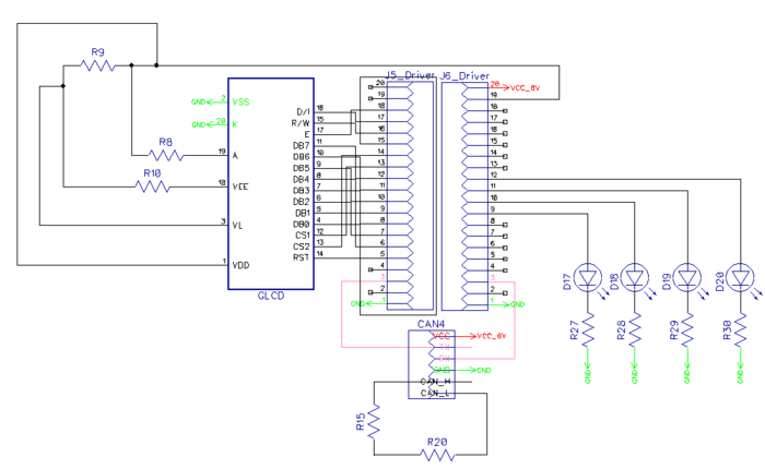
| + | [[File:Driver_Node_HW_Design.png|thumb|700px|caption|left|Driver Node Schematic]] | ||
| + | [[File:DriverSch.png|thumb|700px|caption|center|Driver Node Schematic]] | ||
=== Software Design === | === Software Design === | ||
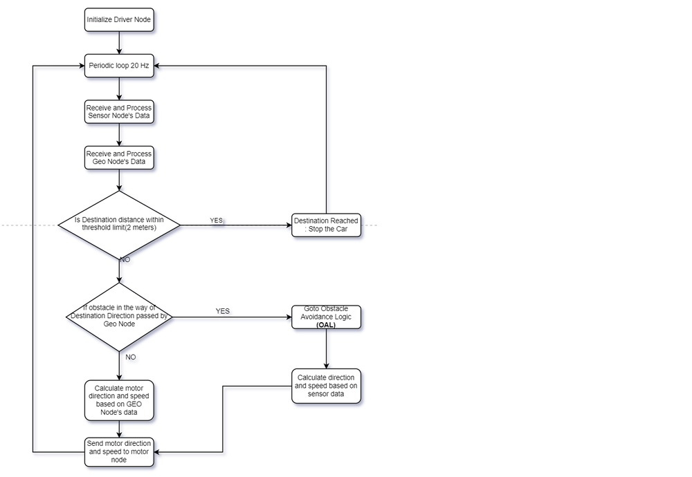
| − | + | The driver node controls the logic of steering the car in the right direction based on the data received from the Sensor and Geo Nodes. The following flowchart describes that process. | |
| + | *Driver Node Flow Chart | ||
| − | + | [[File:FlowChartDriverNode.png|thumb|1000px|caption|center|Driver Node Flow Chart]] | |
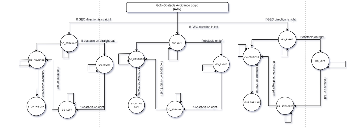
| − | + | In case there are obstacles in the path where the car wants to move to, the following obstacle avoid logic would kick in. | |
| + | *Driver Node Obstacle Avoidance Logic | ||
| − | + | [[File:ObstacleAvoidanceDriverNode.png|thumb|1200px|caption|center|Driver Node Obstacle Avoidance Logic]] | |
| − | + | The work in the Driver Node is done using two different periodic tasks. Here is a description of those periodic tasks and what they do. | |
| − | |||
| − | |||
*1 Hz Loop: | *1 Hz Loop: | ||
**Transmit debug messages over the CAN bus | **Transmit debug messages over the CAN bus | ||
| + | **Transmit messages on the LCD | ||
| + | **Transmit destination reached flag over the CAN Bus | ||
*20 Hz Loop: | *20 Hz Loop: | ||
**Receive Sensor Data | **Receive Sensor Data | ||
**Receive Geo Data | **Receive Geo Data | ||
**Process and Transmit Data(Motor Direction and Speed) to Motor Node | **Process and Transmit Data(Motor Direction and Speed) to Motor Node | ||
| + | *LCD Interface | ||
| + | The LCD interface on the Driver is used to print some important information about the car. This is what it prints. | ||
| + | **Car Speed | ||
| + | **Distance from the Destination | ||
| + | **Car State (Car Stopped from the App, Car Moving, Destination Reached) | ||
| − | === | + | === Technical Challenges === |
| + | *The Driver Node did not have much hardware interfaced on it apart from LCD. So from the hardware side there were no technical challenges. On the software front as well there were not many challenges as unit tests helped debug most of the issues then and there. | ||
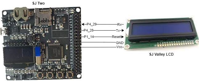
| + | *We initially used GLCD which was configured via GPIOs and it was working perfectly. Hence we created our PCB as per this LCD. But, while testing our car with various speeds and PID logic, it got toppled and damaged the LCD. So, we had to change to SJ Valley LCD, which was configured via the UART interface, at the last moment. So, we used the same location on the PCB to place the LCD and soldered wires below PCB. Hence, this correction was not visible on our end product. | ||
| + | <HR> | ||
| + | <BR/> | ||
| − | == | + | == Mobile Application == |
| + | ''[https://gitlab.com/srikarreddy.narapureddy/roadster-app Gitlab]'' | ||
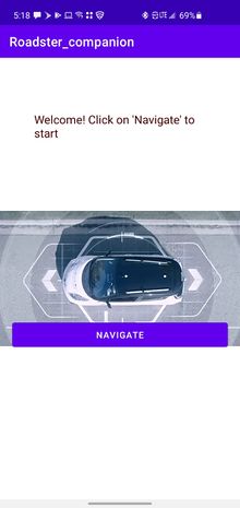
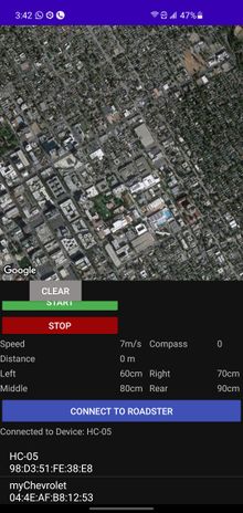
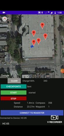
| + | We created a lightweight mobile app to navigate our car, It can communicate with the car via Bluetooth and is capable of sending Destination co-ordinates along with checkpoints. Receive and Update live location on Google Maps, send Start, Stop and Clear commands, Receive and Display Debug Data. | ||
| − | == | + | <div><ul> |
| + | <li style="display: inline-block;">[[File:Roadsterintro.jpeg|thumb|none|220px| Splash screen]] </li> | ||
| + | <li style="display: inline-block;">[[File:roadsterapp1.jpg|thumb|none|220px| Data from roadster]] </li> | ||
| + | <li style="display: inline-block;">[[File:roadsterapp2.jpg|thumb|none|220px| Checkpoints]] </li> | ||
| + | </ul></div> | ||
| + | ===User Interface=== | ||
| + | The app has minimal buttons on the same screen as Google Maps View to confirm the cars current state and location before sending the commands. | ||
| − | == | + | connect_Btn.setOnClickListener(new View.OnClickListener() { |
| + | @Override | ||
| + | public void onClick(View v) { | ||
| + | listPairedDevices(v); | ||
| + | } | ||
| + | }); | ||
| + | clear.setOnClickListener(new View.OnClickListener() { | ||
| + | @Override | ||
| + | public void onClick(View v) { | ||
| + | try { | ||
| + | if(!state) { | ||
| + | mConnectedThread.write("--,\n"); | ||
| + | mMap.clear(); | ||
| + | checkpoints.clear(); | ||
| + | sending_status.setText("Waiting"); | ||
| + | } | ||
| + | else{ | ||
| + | Toast.makeText(getApplicationContext(),"Stop the car First",Toast.LENGTH_SHORT).show(); | ||
| + | } | ||
| + | } | ||
| + | catch (Exception e) | ||
| + | { | ||
| + | Toast.makeText(getApplicationContext(),"Connect to Roadster First",Toast.LENGTH_SHORT).show(); | ||
| + | } | ||
| + | } | ||
| + | }); | ||
| + | stop.setOnClickListener(new View.OnClickListener() { | ||
| + | @Override | ||
| + | public void onClick(View v) { | ||
| + | try { | ||
| + | mConnectedThread.write("!!,\n"); | ||
| + | state=false; | ||
| + | move_camera=false; | ||
| + | car_status.setText(" stopped"); | ||
| + | } | ||
| + | catch (Exception e) | ||
| + | { | ||
| + | Toast.makeText(getApplicationContext(),"Connect to Roadster First",Toast.LENGTH_SHORT).show(); | ||
| + | } | ||
| + | } | ||
| + | }); | ||
| + | start.setOnClickListener(new View.OnClickListener() { | ||
| + | @Override | ||
| + | public void onClick(View v) { | ||
| + | try { | ||
| + | mConnectedThread.write("##,\n"); | ||
| + | state=true; | ||
| + | move_camera=true; | ||
| + | car_status.setText(" started"); | ||
| + | } | ||
| + | catch (Exception e) | ||
| + | { | ||
| + | Toast.makeText(getApplicationContext(),"Connect to Roadster First",Toast.LENGTH_SHORT).show(); | ||
| + | } | ||
| + | } | ||
| + | }); | ||
| + | send_cpts.setOnClickListener(new View.OnClickListener() { | ||
| + | @Override | ||
| + | public void onClick(View v) { | ||
| + | try { | ||
| + | sending_status.setText("...."); | ||
| + | for(int i=0;i<checkpoints.size();i++) { | ||
| + | String cpt="GPS,"+checkpoints.get(i).latitude+","+checkpoints.get(i).longitude+"\n"; | ||
| + | mConnectedThread.write(cpt); | ||
| + | } | ||
| + | sending_status.setText("Sent"); | ||
| + | } | ||
| + | catch (Exception e) | ||
| + | { | ||
| + | Toast.makeText(getApplicationContext(),"Connect to Roadster First",Toast.LENGTH_SHORT).show(); | ||
| + | } | ||
| + | } | ||
| + | }); | ||
| + | === Software Design === | ||
| + | This app has mainly two activities, The main activity and maps activity. | ||
| + | ===Maps Activity=== | ||
| + | This is the only functional activity for the app and is responsible for the Google Maps and Bluetooth related Tasks. User can also dynamically select multiple checkpoints and send them to the bridge node. This is achieved using java vector and OnMapclickListener setup to read each marker placed by the user. | ||
| − | === | + | mMap.setOnMapClickListener(new GoogleMap.OnMapClickListener() { |
| + | @Override | ||
| + | public void onMapClick(LatLng latLng) { | ||
| + | int precision = (int) Math.pow(10,6); | ||
| + | double new_latitude = (double)((int)(precision*latLng.latitude))/precision; | ||
| + | double new_longitude = (double)((int)(precision*latLng.longitude))/precision; | ||
| + | LatLng myloc = new LatLng(latLng.latitude, latLng.longitude); | ||
| + | mMap.addMarker(new MarkerOptions().position(myloc).title("Destination")); | ||
| + | mMap.moveCamera(CameraUpdateFactory.newLatLngZoom(myloc,20)); | ||
| + | checkpoints.add(new LatLng(new_latitude,new_longitude)); | ||
| + | destination_coordinates = "GPS," + new_latitude + "," + new_longitude +"\n"; | ||
| + | } | ||
| + | }); | ||
| − | + | ===Bluetooth=== | |
| + | The Bluetooth connection is initially set up by reading the id and MAC addresses of the selected device, The available devices are displayed on a listView under the connect button. Once the socket is established, Bluetooth module provides read() and write() API used to communicate. | ||
| − | |||
| − | |||
| − | == | + | if(!mBTAdapter.isEnabled()) { |
| − | + | Toast.makeText(getBaseContext(), "Bluetooth not on", Toast.LENGTH_SHORT).show(); | |
| − | + | return; | |
| + | } | ||
| + | mBluetoothStatus.setText("Connecting..."); | ||
| + | // Get the device MAC address, which is the last 17 chars in the View | ||
| + | String info = ((TextView) v).getText().toString(); | ||
| + | final String address = info.substring(info.length() - 17); | ||
| + | final String name = info.substring(0,info.length() - 17); | ||
| + | new Thread() | ||
| + | { | ||
| + | public void run() { | ||
| + | boolean fail = false; | ||
| + | BluetoothDevice device = mBTAdapter.getRemoteDevice(address); | ||
| + | try { | ||
| + | mBTSocket = createBluetoothSocket(device); | ||
| + | } catch (IOException e) { | ||
| + | fail = true; | ||
| + | Toast.makeText(getBaseContext(), "Socket creation failed", Toast.LENGTH_SHORT).show(); | ||
| + | } | ||
| + | // Establish the Bluetooth socket connection. | ||
| + | try { | ||
| + | mBTSocket.connect(); | ||
| + | } catch (IOException e) { | ||
| + | try { | ||
| + | fail = true; | ||
| + | mBTSocket.close(); | ||
| + | mHandler.obtainMessage(CONNECTING_STATUS, -1, -1) | ||
| + | .sendToTarget(); | ||
| + | } catch (IOException e2) { | ||
| + | Toast.makeText(getBaseContext(), "Socket creation failed", Toast.LENGTH_SHORT).show(); | ||
| + | } | ||
| + | } | ||
| + | if(fail == false) { | ||
| + | mConnectedThread = new ConnectedThread(mBTSocket); | ||
| + | mConnectedThread.start(); | ||
| + | mHandler.obtainMessage(CONNECTING_STATUS, 1, -1, name) | ||
| + | .sendToTarget(); | ||
| + | } | ||
| − | |||
| − | |||
| − | + | The Bridge node sends data in string format with end of line chars, The Bluetooth handler concatenates the received data and waits for the "end of line" before trying to parse it. Below is the code snippet that parses the incoming stream with location and debug data sent by the bridge node. | |
| − | |||
| − | |||
| − | The Bluetooth | ||
if(readMessage.indexOf("\n")>0) { | if(readMessage.indexOf("\n")>0) { | ||
| Line 646: | Line 1,192: | ||
} | } | ||
readMessage=""; | readMessage=""; | ||
| − | |||
| − | |||
| − | |||
| − | |||
| − | |||
=== Technical Challenges === | === Technical Challenges === | ||
| − | + | Given no experience in Android Development, we had to start from the basics about the activities, message passing etc. The initial challenge was to understand the google maps API and generate the API key to access google cloud to implement the map view and markers. Implementing Bluetooth communication required scanning the list of paired devices and acquire the MAC address required to open a socket using the provided API. Fortunately, there are many example implementations to go through. We decided to use a similar line buffer that is used in the Geo node to read the debug data sent from the app, this helped solve the challenge of parsing the group of variables sent by the bridge node by reading from the CAN bus. | |
| − | |||
| Line 663: | Line 1,203: | ||
== Conclusion == | == Conclusion == | ||
| − | |||
| − | + | * Embedded project are generally single board projects. The mandatory use of CAN bus required a great deal of collaboration, where all board are interdependent and the system design should be robust to make it work every single time, the car is used for its intended purpose. | |
| + | *Unit testing helps in early phase of the project, where the hardware setup is not ready yet, but one needs to start coding to get ahead of the curve and start building logic. This helps in troubleshooting the hardware as well. | ||
=== Project Video === | === Project Video === | ||
| + | |||
| + | https://youtu.be/Q24ghJRe9VM | ||
=== Project Source Code === | === Project Source Code === | ||
| + | ''[https://gitlab.com/nimit.patel/roadster Repository link for Autonomous RC Car]'' | ||
| + | ''[https://gitlab.com/srikarreddy.narapureddy/roadster-app Repository for Android App]'' | ||
=== Advise for Future Students === | === Advise for Future Students === | ||
| − | + | * Get the hardware modules and test the same with SJ2 (Before the Mid Semester exams). Once this is done, create a PCB and mount devices and then start the extensive software testing. Considering the car is moving object, temporary connections over bread board and zero PCB might work, but reliability will remain a doubt at the back of the head. Eliminate the same by creating the PCB early. You might even want to iterate to a second PCB, once you are a few weeks into testing and want to change amend previous mistakes/improve existing layout and placements. The time and effort this will save is worth it. | |
| + | *Once the hardware is nearing its completion, the Mobile app should be ready in its rudimentary form. Having a hand held debug device is more useful, compared to using PCAN dongle which is great for static testing. | ||
| + | * The software will take multiple iteration by testing your car in various field scenarios. This is not a project which can be completed a night before demo. Keep a healthy amount of time for testing. | ||
| + | * The sole working power socket available in university outside of the university buildings is available on the top floor of the tenth street car garage. This is especially useful when testing in field. | ||
=== Acknowledgement === | === Acknowledgement === | ||
| + | * Building a hardware project without the availability of a electronics lab of the university which had been shut, due to COVID-19 pandemic tested our resourcefulness to our extremes.Considering the remote nature of course work, resource availability in any shape or form from university was sadly non existent. All the team members should be appreciated for their unwavering enthusiasm to make this a success story. | ||
| + | * Preet's advice for buying quality hardware parts should be followed to the line. | ||
=== References === | === References === | ||
| + | http://socialledge.com/sjsu/index.php/Industrial_Application_using_CAN_Bus | ||
| + | <Br> | ||
Latest revision as of 05:36, 29 May 2021
Contents
Roadster
Abstract
Roadster is a battery powered autonomous car, that drives itself to a specified destination and avoids any obstacles that comes its way. The car infrastructure has four Nodes (Geo, Sensor, Driver and Motor) that communicate over the CAN bus and an android application interface to set the destination location. In order to make an informed decision the car processes Geo and Sensor Node’s data which is used to steer the car in the right direction.
Introduction
The project was divided into 5 modules:
- Sensor Node- Detecting obstacles in the vicinity of the car to avoid hitting the obstacle and maneuver around the same.
- Geo and Bridge Node- Provide heading for car to reach destination. Communicate over blue tooth with mobile application. Battery state.
- Driver Node- Manipulate turn angles and forward/reverse speed based on the inputs from Sensor and Geo nodes
- Motor Node- PID control logic to attain the said speed/direction desired by driver node.
- Android Application- Dashboard for real time data from car. Send instruction such as destination, way points and start/stop.
Team Members & Responsibilities
Roadster GitLab - Gitlab
Tejas Pidwalkar LinkedIn
- Sensor Node
- Driver Node
- Wiki Page Update
- Integration Testing
Nimit Patel LinkedIn
- Geo And Bridge Node
- Wiki Page Update
- Integration Testing
Tirth Pandya LinkedIn
- Motor Node
- PCB design
- Wiki Page Update
- Integration Testing
Srikar Reddy LinkedIn
- Android Application
- Wiki Page Update
Sourab Gupta LinkedIn
- Driver Node
- Wiki Page Update
- Integration Testing
Schedule
| Week# | Start Date | End Date | Task | Actual Completion | Status |
|---|---|---|---|---|---|
| 1
03/01 to 03/07 Start of Phase 1 |
|
|
|
|
|
| 2
03/08 to 03/14 |
|
|
|
|
|
| 3
03/15 to 03/21 |
|
|
|
|
|
| 4
03/22 to 03/28 |
|
|
|
|
|
| 5
03/29 to 04/04 End of Phase 1 |
|
|
|
|
|
| 6
04/05 to 04/11 Start of Phase 2 |
|
|
|
|
|
| 7
04/12 to 04/18 |
|
|
|
|
|
| 8
04/19 to 04/25 End of Phase 2 |
|
|
|
|
|
| 9
04/26 to 05/02 Start of Phase 3 |
|
|
|
|
|
| 10
05/03 to 05/09 |
|
|
|
|
|
| 11
05/10 to 05/16 End of Phase 3 |
|
|
|
|
|
Parts List & Cost
| Item# | Part Desciption | Vendor | Qty | Cost |
|---|---|---|---|---|
| 1 | RC Car | Traxxas [1] | 1 | $250.00 |
| 2 | CAN Transceivers MCP2551-I/P | Comimark [2] | 5 | $7.00 |
| 3 | Ultrasonic Sensors | Max Botix[3] | 5 | $150.00 |
| 4 | GPS and Antenna | Adafruit[4] | 1 | $60.00 |
| 5 | HC05 bluetooth RF Transreceiver | HiLetgo[5] | 1 | $12.59 |
| 6 | Triple-axis Accelerometer | Adafruit[6] | 1 | $21.40 |
| 7 | Traxxas RPM Sensor | Traxxas[7] | 1 | $12 |
| 8 | Discrete Electronic Components | Generic[8] | 1 | $28.75 |
| 9 | Buck-Boost Voltage Regulator | Generic[9] | 1 | $11.99 |
| 10 | Traxxas Telemetry Trigger magnet & holder | Traxxas[10] | 1 | $6.35 |
| 11 | Acrylic Sheet | Tap Plastic | 1 | $12 |
| 12 | Battery | Amazon[11] | 1 | $26.99 |
| 13 | Traxxas Battery and Charger | Amazon[12] | 1 | $55.94 |
Printed Circuit Board
PCB Schematic
PCB Design
CAN Communication
We use controller area network to broadcast data between the 4 nodes. All nodes are connected to each other through a physically conventional two wire bus. The wires are a twisted pair with 120 Ω resistors at each ends of the bus. 1s and 0s are transmitted as CAN High(0V difference) and Can Low(2v difference). A CAN frame has the following contents:
- Data Length Code (4bits)
- Remote Transmission Request.
- ID extend bit.
- Message ID (11 bit or 29 bit)
- Data bytes( depends on DLC)
- CRC
Arbitration: No two nodes will transmit at the same time because if arbitration. A lower Message-ID has a Higher priority on the CAN bus since 0 is the dominant bit.
Bit Stuffing: CAN bus stuffs extra bits when a long chain of multiple 1's or 0's occur to improve CAN integrity.
| Sr. No | Message ID | Message function | Receivers |
|---|---|---|---|
| Driver Controller | |||
| 1 | 300 | speed and steering direction for the motor. | Motor |
| 2 | 310 | Destination reached | Sensor |
| Sensor Controller | |||
| 1 | 200 | Sensor sonars from front, back, left ,right sensor | Driver |
| Motor Controller | |||
| 8 | 700 | motor speed, motor direction | Driver |
| Geo and Bridge Controller | |||
| 1 | 400 | Bearing, Heading and Distance | Driver |
| Debug messages | |||
| 1 | 851 | Driver Debug | SENSOR,MOTOR,GEO_AND_BRIDGE |
| 1 | 811 | Motor Debug | SENSOR,MOTOR,GEO_AND_BRIDGE |
| 1 | 801 | Sensor Debug | SENSOR,MOTOR,GEO_AND_BRIDGE |
Hardware Design
DBC File
VERSION ""

NS_ :
	BA_
	BA_DEF_
	BA_DEF_DEF_
	BA_DEF_DEF_REL_
	BA_DEF_REL_
	BA_DEF_SGTYPE_
	BA_REL_
	BA_SGTYPE_
	BO_TX_BU_
	BU_BO_REL_
	BU_EV_REL_
	BU_SG_REL_
	CAT_
	CAT_DEF_
	CM_
	ENVVAR_DATA_
	EV_DATA_
	FILTER
	NS_DESC_
	SGTYPE_
	SGTYPE_VAL_
	SG_MUL_VAL_
	SIGTYPE_VALTYPE_
	SIG_GROUP_
	SIG_TYPE_REF_
	SIG_VALTYPE_
	VAL_
	VAL_TABLE_

BS_:

BU_: DRIVER MOTOR SENSOR GEO_AND_BRIDGE DEBUG

BO_ 200 SENSOR_SONARS: 5 SENSOR
 SG_ SENSOR_SONARS_left : 0|10@1+ (1,0) [0|800] "cm" DRIVER
 SG_ SENSOR_SONARS_right : 10|10@1+ (1,0) [0|0] "cm" DRIVER
 SG_ SENSOR_SONARS_middle : 20|10@1+ (1,0) [0|0] "cm" DRIVER
 SG_ SENSOR_SONARS_rear : 30|10@1+ (1,0) [0|0] "cm" DRIVER

BO_ 300 DRIVER_TO_MOTOR: 2 DRIVER
 SG_ MOTOR_speed : 0|8@1+ (0.1,-12.5) [-12.5|12.5] "m/s" MOTOR
 SG_ MOTOR_direction : 8|7@1+ (1,-45) [-45|45] "degree" MOTOR

BO_ 310 DRIVER_BROADCAST: 1 DRIVER
 SG_ DEST_reached : 0|8@1+ (1,0) [0|0] "flag" SENSOR

BO_ 400 GEO_CONTROLLER_COMPASS: 6 GEO_AND_BRIDGE
  SG_ HEADING : 0|12@1+ (1,0) [0|359] "Degrees" DRIVER
  SG_ BEARING : 12|12@1+ (1,0) [0|359] "Degrees" DRIVER
  SG_ DISTANCE : 24|17@1+ (0.01,0) [0|0] "Meters" DRIVER

BO_ 401 GEO_CONTROLLER_COMPASS_DEBUG: 9 GEO_AND_BRIDGE
  SG_ WAYPOINT_COUNT : 0|8@1+ (1,0) [0|16] "" DEBUG
  SG_ STATUS : 8|8@1+ (1,0) [0|359] "Degrees" DEBUG
  SG_ DISTANCE_TO_WAYPOINT : 16|12@1+ (0.01,0) [0|0] "Meters" DEBUG
  SG_ HEADING_TO_WAYPOINT : 28|12@1+ (1,0) [0|359] "Degrees" DEBUG
  SG_ BEARING_TO_WAYPOINT : 40|12@1+ (1,0) [0|359] "Degrees" DEBUG
  SG_ HEADING_RAW : 52|12@1+ (1,0) [0|359] "Degrees" DEBUG
  SG_ WAYPOINT_CURRENT : 64|8@1+ (1,0) [0|16] "" DEBUG

BO_ 700 MOTOR_TO_DRIVER: 8 MOTOR
 SG_ MOTOR_speed:0|8@1+ (0.1,-12.5) [-12.5|12.5] "m/s" DRIVER
 SG_ MOTOR_direction : 8|7@1+ (1,-45) [-45|45] "degree" DRIVER

BO_ 851 DRIVER_DEBUG_DATA: 1 DEBUG
 SG_ forwardDrivingState:0|2@1+ (1,0) [0|0] "" SENSOR,MOTOR,GEO_AND_BRIDGE
 SG_ reverseDrivingState: 2|2@1+ (1,0) [0|0] "" SENSOR,MOTOR,GEO_AND_BRIDGE
 SG_ isRightSteeringPossible:4|2@1+ (1,0) [0|0] "" SENSOR,MOTOR,GEO_AND_BRIDGE
 SG_ isLeftSteeringPossible:6|2@1+ (1,0) [0|0] "" SENSOR,MOTOR,GEO_AND_BRIDGE

BO_ 801 SENSOR_DEBUG_DATA: 8 DEBUG
 SG_ LEFT_sensor_raw:0|16@1+ (1,0) [0|0] "cm" SENSOR,MOTOR,GEO_AND_BRIDGE
 SG_ RIGHT_sensor_raw: 16|16@1+ (1,0) [0|0] "cm" SENSOR,MOTOR,GEO_AND_BRIDGE
 SG_ FRONT_sensor_raw: 32|16@1+ (1,0) [0|0] "cm" SENSOR,MOTOR,GEO_AND_BRIDGE
 SG_ REAR_sensor_raw: 48|16@1+ (1,0) [0|0] "cm" SENSOR,MOTOR,GEO_AND_BRIDGE

BO_ 811 MOTOR_DEBUG_DATA: 8 DEBUG
 SG_ MOTOR_rps_value:0|32@1+ (1,0) [0|0] "rps value" SENSOR,DRIVER,GEO_AND_BRIDGE
 SG_ MOTOR_pwm_value:32|8@1+ (0.01,0) [0|0] "dc motor pwm value" SENSOR,DRIVER,GEO_AND_BRIDGE

BO_ 1000 DRIVER_HEARTBEAT: 1 DRIVER
 SG_ DRIVER_HEARTBEAT_cmd : 0|8@1+ (1,0) [0|0] "" SENSOR,MOTOR,GEO_AND_BRIDGE

BO_ 1100 MOTOR_HEARTBEAT: 1 DRIVER
 SG_ MOTOR_HEARTBEAT_cmd : 0|8@1+ (1,0) [0|0] "" SENSOR,DRIVER,GEO_AND_BRIDGE

BO_ 1200 SENSOR_HEARTBEAT: 1 DRIVER
 SG_ SENSOR_HEARTBEAT_cmd : 0|8@1+ (1,0) [0|0] "" MOTOR,DRIVER,GEO_AND_BRIDGE

BO_ 1300 GEO_HEARTBEAT: 1 DRIVER
 SG_ GEO_HEARTBEAT_cmd : 0|8@1+ (1,0) [0|0] "" SENSOR,MOTOR,DRIVER

CM_ BU_ DRIVER "The driver controller driving the car";
CM_ BU_ MOTOR "The motor controller of the car";
CM_ BU_ SENSOR "The sensor controller of the car";
CM_ BO_ 100 "Sync message used to synchronize the controllers";
CM_ SG_ 100 DRIVER_HEARTBEAT_cmd "Heartbeat command from the driver";

BA_DEF_ "BusType" STRING ;
BA_DEF_ BO_ "GenMsgCycleTime" INT 0 0;
BA_DEF_ SG_ "FieldType" STRING ;

BA_DEF_DEF_ "BusType" "CAN";
BA_DEF_DEF_ "FieldType" "";
BA_DEF_DEF_ "GenMsgCycleTime" 0;

BA_ "GenMsgCycleTime" BO_ 100 1000;
BA_ "GenMsgCycleTime" BO_ 200 50;
BA_ "FieldType" SG_ 100 DRIVER_HEARTBEAT_cmd "DRIVER_HEARTBEAT_cmd";

VAL_ 100 DRIVER_HEARTBEAT_cmd 2 "DRIVER_HEARTBEAT_cmd_REBOOT" 1 "DRIVER_HEARTBEAT_cmd_SYNC" 0 "DRIVER_HEARTBEAT_cmd_NOOP" ;
Sensor ECU
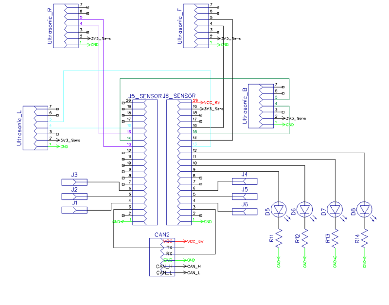
<Picture and link to Gitlab> Gitlab link to Sensor Node Firmware: https://gitlab.com/nimit.patel/roadster/-/tree/Main/Sensor_Node
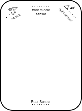
The sensor controller node is responsible for interfacing with Ultrasonic sensors to know obstacles’ distance from the vehicle. We have used MaxBotix 1010 LV-EZ1 sensors for the right and left positions and MaxBotix 1000 LV-EZ0 sensor in the middle front position (To have a wider beam range of obstacle detection in blind spots).
Below is the beam pattern for both sensors.
Hardware Design
Sensor Controller Schematic
Board Pin Connections
Sensors are interfaced with combination of GPIO, ADC Pins on SJTWo board. Below is the descriptive pin layout:
| Sr. No. | SJTwo board Pin | Maxbotix sensor Pin | Function |
|---|---|---|---|
| 1 | ADC2-P0.25 | AN(Front sensor) | ADC input from front sensor |
| 2 | ADC3-P0.26 | AN(Rear Sensor) | ADC input from rear sensor |
| 3 | ADC4-P1.30 | AN(Left Sensor) | ADC input from left sensor |
| 4 | ADC5-P1.31 | AN(Right Sensor) | ADC input from right sensor |
| 5 | GPIO-P0.6 | RX(Left Sensor) | Trigger for left sensor |
| 6 | GPIO-P0.7 | RX(Front Sensor) | Trigger for front sensor |
| 7 | GPIO-P0.8 | RX(Right Sensor) | Trigger for right sensor |
| 8 | GPIO-P0.9 | RX(Rear Sensor) | Trigger for rear sensor |
Software Design
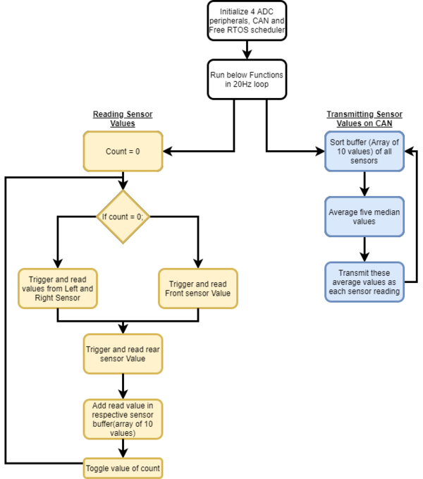
The sensor node mainly does two activity viz. 1) Read sensor values, 2) Transmit obstacle distance over CAN bus. Both of these activities happen in a 20Hz periodic callback.
1. Read Sensor Values
- Sensors are mounted at four locations as mentioned below diagram. To read these sensor values, we initialized and configured 4 sensors using 4 ADCs viz ADC2, ADC3, ADC4, and ADC5. Considering the front 3 sensors' close proximity and possible beam interference, we decided to range extreme front sensors at a time and the middle front next in sequence while in a 20 Hz loop. And the rear sensor is triggered regularly. All the sensor values are digitally converted in the range of 0 to 4096 (12 bit ADC). These values are converted to distance format in centimeter unit using formula conv_val = (raw_val * 0.3182) - 0.3959.
- Now, to avoid frequent noise pulses, we used a median filter. We created an array of 10 elements for each sensor and maintained a write index to track the current update position. Thus, all read values have been updated in the buffer which acts as a circular buffer as we start overwriting from the start index.
2. Transmit obstacle distance over CAN bus:
- Sensor node is responsible for broadcasting all four sensor values in terms of distance in centimeter over CAN bus. To broadcast filtered values, it first sorts the existing values in the respective allocated sensor buffer. Then it takes the mean of five median values. It does the same thing for all four sensors. Finally, it transmits those values over CAN bus. Below flow chart gives the detailed flow of code at a high level.
Technical Challenges
Neighboring Sensor Interference:
- As explained above, we have mounted three ultrasonic sensors in the front, and those were configured to range in continuous mode, in which sensors were continuously measuring distance by transmitting beam. Out of 3, the middle sensor is of type with wider beam to detect blind spots ahead.
- Most of the time, we observed that the obstacle in the middle sensor range used also gets detected by the left/right sensor, which disturbs driving logic. This used to happen due to sensor beam interference among three sensors.
- To solve this problem, we decided to trigger sensor beams in such time intervals that they won’t interfere with neighboring ones. We used the Rx pin of the sensor to trigger ranging and scheduled to trigger left and right sensor at one time and middle sensor next time. This sequence helped us avoid interference altogether.
Frequent noisy measurements:
- While reading the obstacle distance, it used to change suddenly to some random value, and that used to disturb driving logic. To get noise-free readings from sensors, we implemented a median filter. All the read values from sensors have been collected in the respective buffer of 10 elements. While sending obstacle distance on CAN bus, the median filter sort the buffer and takes an average of 5 median values. This way, it helped us to remove almost all noisy values.
Motor ECU
Hardware Design
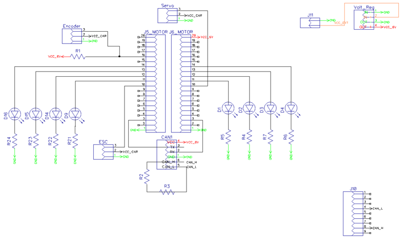
The motor node(SJ-2) interfaces primarily interfaces with:
- Traxass Motor ESC over PWM
- Traxass RPM Sensor over GPIO Interrupt
- Traxass Servo Motor over PWM
All these three components have 3 pins each. The functionalities of these pins are mentioned in the table below.
| Module | Black | Red | White |
|---|---|---|---|
| ESC | Ground | Vout : 6 V | PWM Input |
| Servo | Ground | Vin : 6 V | PWM Input |
| RPM Sensor | Ground | Vin : 6 V | Pulse Output |
Software Design
The motor node acts based on the speed and direction received over CAN bus from the Driver Node. The positive speed values are treated as forward motion and the negative speed values are considered to be the reverse motion of the RC car.
The steering angles are divided into 5-degree segments and the motor node sends the pre-defined pwm duty cycle of the particular segment to the servo motor depending on the angle value received from the driver node.
Technical Challenges
- Firstly, the Traxxas motor ESC and other Traxass parts are members of the Traxxas Hobby Parts family, and they are not intended for development purposes. This is why there are no technical specification documents or any program/development guides available. One needs to test the motor ESC by feeding the PWM duty cycles in various sequences at various duty cycle percentages. We used the Remote control to reproduce some scenarios where the ESC was behaving unexpectedly.
- The ESC configuration changes to the Lipo battery state if the Lipo battery is used. If one switches back to the NiMH battery, then the ESC starts flashing the led in a green-red repeated sequence, and the ESC power button stops working. In this scenario, there is a calibration process that can save your boat and can make the ESC function normally again. Follow this procedure : ESC Calibration
- Another challenge with the motor node program development is that you cannot rely on unit testing. Whoever works on the motor node, should make sure that the sequence of the duty cycles being fed to the ESC produces the expected results on the motor as well. The forward-reverse transitioning and the speed controlling both can be a bit tricky. Also, the hard brake logic can take a while to get working properly.
- Some useful reference values for the ESC are : 15% -> Neutral; 15.8%-> Minimum forward speed, 10%->Full reverse speed.
Geographical And Bridge Controller
Repository link for Geo Controller
Hardware Design
The SJ2 board communicates with:
- Bluettoth transreceiver over UART
- LSM303DLHC over I2C
- GPS model over UART
- Battery monitoring
Considering the orientation of the car changes as it travel along the land, tilt compensation logic for heading calculation using the magnetometer is a must for accurate measurement. Without the tilt compensation algorithm which uses the onboard accelorometer, the heading computation can have error up to 60 degrees, which has the potential to send the car off course.
For battery monitoring, the values for the voltage divider should be chosen such that the full range of the onboard ADC can be efficiently used. Depending one the cell type of the battery, the discharge curve can be use to map the charge state corresponding to voltage level. This method has its flaws and sophisticated techniques involving Coulomb count yields far better results, however, the technique discussed above suffices the needs of our project. Charge state of battery transmitted over Mobile app, greatly facilitates the charging schedule while testing and final demo day.
Software Design
The periodic scheduler for Geo Controller Node does the following functionalities:
- In 10Hz periodic callback:
- gps__update() : Fetch GPS data from GPS controller.
- geo_compass__periodic_send() : Reads the Magnetometer and accelerometer values from Compass controller and convert those to current heading data.
- In 100Hz periodic callback:
- bluetooth__run_once() : Send specified data to android application via Bluetooth.
The GEO controller is divided into 5 parts.
- The current location of the car is determined using the GPS.
- The current magnetic heading of car is determined using the on board compass.
- The way point calculation determines the nearest way point continuously by computing the distance using Haversine formula and current location using GPS.
- The heading is also computed using the Haversine formula and the difference between the actual and required is sent over the CAN bus for heading correction.
- Alternatively, once the car is within the threshold distance, next way point is selected and the car heads to the next way point.
Technical Challenges
- The GPS module sends data at 9600 baud rate, updating the data every one second. The data update rate needs to be updated to 10Hz for fast maneuvering and course correction of the car. If the update frequency is updated, the data sent over the UART is higher than it can handle in 10Hz periodic function. Hence, only GPGGA messages should be enabled to extract the required data and reduce the time spent in parsing the incoming string. NEMA (PMTK) messages should be correctly configured on the module for desired functioning.
- Heading calculation without the tilt compensation logic using the onboard accelorometer of LSM303 is in accurate. Reading accelorometer values requires and offset of 0x80 to the byte addressing of the accelorometer read. Magnetometer need no such offset. This is weird, considering both the I2C devices reside on the same physical chip.
- Using data type as float as opposed to double, utilizes the onboard FPU, which is faster. Double utilizes software implementation, which takes more clock cycle. Considering extensive use of math library in distance/heading measurement and tilt compensation algorithm, completing the task with the periodic is of at most importance.
- GPS fix is best when when there are no obstruction above the module. Module requires clear wide view of sky for a fast fix and error free location detection.
- LSM303DLHC is sensitive to even weak magnetic field interference. Place the chip devoid of such active/passive magnetic fields.
- Calibrating LSM303 is a must to get accurate heading values. 2-point calibration worked just fine for our team. More sophisticated methods are available too.
Driver Node
https://gitlab.com/nimit.patel/roadster/-/tree/Main/Driver_Node
Hardware Design
The Driver Node has one peripheral connected to it and that is the LCD screen.
Software Design
The driver node controls the logic of steering the car in the right direction based on the data received from the Sensor and Geo Nodes. The following flowchart describes that process.
- Driver Node Flow Chart
In case there are obstacles in the path where the car wants to move to, the following obstacle avoid logic would kick in.
- Driver Node Obstacle Avoidance Logic
The work in the Driver Node is done using two different periodic tasks. Here is a description of those periodic tasks and what they do.
- 1 Hz Loop:
- Transmit debug messages over the CAN bus
- Transmit messages on the LCD
- Transmit destination reached flag over the CAN Bus
- 20 Hz Loop:
- Receive Sensor Data
- Receive Geo Data
- Process and Transmit Data(Motor Direction and Speed) to Motor Node
- LCD Interface
The LCD interface on the Driver is used to print some important information about the car. This is what it prints.
- Car Speed
- Distance from the Destination
- Car State (Car Stopped from the App, Car Moving, Destination Reached)
Technical Challenges
- The Driver Node did not have much hardware interfaced on it apart from LCD. So from the hardware side there were no technical challenges. On the software front as well there were not many challenges as unit tests helped debug most of the issues then and there.
- We initially used GLCD which was configured via GPIOs and it was working perfectly. Hence we created our PCB as per this LCD. But, while testing our car with various speeds and PID logic, it got toppled and damaged the LCD. So, we had to change to SJ Valley LCD, which was configured via the UART interface, at the last moment. So, we used the same location on the PCB to place the LCD and soldered wires below PCB. Hence, this correction was not visible on our end product.
Mobile Application
Gitlab We created a lightweight mobile app to navigate our car, It can communicate with the car via Bluetooth and is capable of sending Destination co-ordinates along with checkpoints. Receive and Update live location on Google Maps, send Start, Stop and Clear commands, Receive and Display Debug Data.
User Interface
The app has minimal buttons on the same screen as Google Maps View to confirm the cars current state and location before sending the commands.
       connect_Btn.setOnClickListener(new View.OnClickListener() {
           @Override
           public void onClick(View v) {
               listPairedDevices(v);
           }
       });
       clear.setOnClickListener(new View.OnClickListener() {
           @Override
           public void onClick(View v) {
               try {
                   if(!state) {
                       mConnectedThread.write("--,\n");
                       mMap.clear();
                       checkpoints.clear();
                       sending_status.setText("Waiting");
                   }
                   else{
                       Toast.makeText(getApplicationContext(),"Stop the car First",Toast.LENGTH_SHORT).show();
                   }
               }
               catch (Exception e)
               {
                   Toast.makeText(getApplicationContext(),"Connect to Roadster First",Toast.LENGTH_SHORT).show();
               }
           }
       });
       stop.setOnClickListener(new View.OnClickListener() {
           @Override
           public void onClick(View v) {
               try {
                   mConnectedThread.write("!!,\n");
                   state=false;
                   move_camera=false;
                   car_status.setText("   stopped");
               }
               catch (Exception e)
               {
                   Toast.makeText(getApplicationContext(),"Connect to Roadster First",Toast.LENGTH_SHORT).show();
               }
           }
       });
       start.setOnClickListener(new View.OnClickListener() {
           @Override
           public void onClick(View v) {
               try {
                   mConnectedThread.write("##,\n");
                   state=true;
                   move_camera=true;
                   car_status.setText("   started");
               }
               catch (Exception e)
               {
                   Toast.makeText(getApplicationContext(),"Connect to Roadster First",Toast.LENGTH_SHORT).show();
               }
           }
       });
       send_cpts.setOnClickListener(new View.OnClickListener() {
           @Override
           public void onClick(View v) {
               try {
                   sending_status.setText("....");
               for(int i=0;i<checkpoints.size();i++) {
                   String cpt="GPS,"+checkpoints.get(i).latitude+","+checkpoints.get(i).longitude+"\n";
                   mConnectedThread.write(cpt);
               }
               sending_status.setText("Sent");
               }
               catch (Exception e)
               {
                   Toast.makeText(getApplicationContext(),"Connect to Roadster First",Toast.LENGTH_SHORT).show();
               }
           }
       });
Software Design
This app has mainly two activities, The main activity and maps activity.
Maps Activity
This is the only functional activity for the app and is responsible for the Google Maps and Bluetooth related Tasks. User can also dynamically select multiple checkpoints and send them to the bridge node. This is achieved using java vector and OnMapclickListener setup to read each marker placed by the user.
mMap.setOnMapClickListener(new GoogleMap.OnMapClickListener() {
           @Override
           public void onMapClick(LatLng latLng) {
               int precision = (int) Math.pow(10,6);
               double new_latitude = (double)((int)(precision*latLng.latitude))/precision;
               double new_longitude = (double)((int)(precision*latLng.longitude))/precision;
               LatLng myloc = new LatLng(latLng.latitude, latLng.longitude);
               mMap.addMarker(new MarkerOptions().position(myloc).title("Destination"));
               mMap.moveCamera(CameraUpdateFactory.newLatLngZoom(myloc,20));
               checkpoints.add(new LatLng(new_latitude,new_longitude));
               destination_coordinates = "GPS," + new_latitude + "," + new_longitude +"\n";
           }
       });
Bluetooth
The Bluetooth connection is initially set up by reading the id and MAC addresses of the selected device, The available devices are displayed on a listView under the connect button. Once the socket is established, Bluetooth module provides read() and write() API used to communicate.
           if(!mBTAdapter.isEnabled()) {
               Toast.makeText(getBaseContext(), "Bluetooth not on", Toast.LENGTH_SHORT).show();
               return;
           }
           mBluetoothStatus.setText("Connecting...");
           // Get the device MAC address, which is the last 17 chars in the View
           String info = ((TextView) v).getText().toString();
           final String address = info.substring(info.length() - 17);
           final String name = info.substring(0,info.length() - 17);
           new Thread()
           {
               public void run() {
                   boolean fail = false;
                   BluetoothDevice device = mBTAdapter.getRemoteDevice(address);
                   try {
                       mBTSocket = createBluetoothSocket(device);
                   } catch (IOException e) {
                       fail = true;
                       Toast.makeText(getBaseContext(), "Socket creation failed", Toast.LENGTH_SHORT).show();
                   }
                   // Establish the Bluetooth socket connection.
                   try {
                       mBTSocket.connect();
                   } catch (IOException e) {
                       try {
                           fail = true;
                           mBTSocket.close();
                           mHandler.obtainMessage(CONNECTING_STATUS, -1, -1)
                                   .sendToTarget();
                       } catch (IOException e2) {
                           Toast.makeText(getBaseContext(), "Socket creation failed", Toast.LENGTH_SHORT).show();
                       }
                   }
                   if(fail == false) {
                       mConnectedThread = new ConnectedThread(mBTSocket);
                       mConnectedThread.start();
                       mHandler.obtainMessage(CONNECTING_STATUS, 1, -1, name)
                               .sendToTarget();
                   }
The Bridge node sends data in string format with end of line chars, The Bluetooth handler concatenates the received data and waits for the "end of line" before trying to parse it. Below is the code snippet that parses the incoming stream with location and debug data sent by the bridge node.
                   if(readMessage.indexOf("\n")>0) {
                       message = new StringTokenizer(readMessage, "\n");
                       StringTokenizer st;
                       while (message.hasMoreTokens()) {
                           st = null;
                           received_line = message.nextToken();
                           st = new StringTokenizer(received_line, ",");
                           try {
                               read = st.nextToken();
                           } catch (Exception e) {
                               continue;
                           }
                           if (read.compareTo("GPS") == 0) {
                               try {
                                   LatLng current_location = new LatLng(Double.parseDouble(st.nextToken()), Double.parseDouble(st.nextToken()));
                                   waypoint.setText(st.nextToken("\n").replace(",", ""));
                                   prev.remove();
                                   prev = mMap.addMarker(new
                                          MarkerOptions().position(current_location).anchor(0.5f,0.5f).rotation(compass_value).title("Roadster")
                                          .icon(BitmapFromVector(getApplicationContext(), R.drawable.ic_baseline_directions_car_filled_24)));
                            if (state || init) {
                                       mMap.moveCamera(CameraUpdateFactory.newLatLng(current_location));
                                       if (current_location.latitude != 0) init = false;
                                   }
                               } catch (Exception e) {
                               }
                           } else if (read.compareTo("speed") == 0) {
                               try {
                                   speed.setText(st.nextToken("\n").replace(",", "") + "m/s");
                               } catch (Exception e) {
                               }
                           } else if (read.compareTo("sens") == 0) {
                               try {
                                   left.setText(st.nextToken() + "cm");
                                   right.setText(st.nextToken() + "cm");
                                   center.setText(st.nextToken() + "cm");
                                   back.setText(st.nextToken("\n").replace(",", "") + "cm");
                               } catch (Exception e) {
                               }
                           } else if (read.compareTo("comp") == 0) {
                               try {
                                   compass.setText(st.nextToken());
                                   String compass_s=st.nextToken("\n").replace(",", "");
                                   compass_raw.setText(compass_s);
                                   compass_value =Integer.parseInt(compass_s);
                                   prev.setAnchor(0.5f,0.5f);
                                   prev.setRotation(compass_value);
                               } catch (Exception e) {
                               }
                           } else if (read.compareTo("dist") == 0) {
                               try {
                                   String dis=st.nextToken("\n").replace(",", "");
                                   distance.setText(dis+"m");
                                   //int prog=(int)Float.parseFloat(dis)%200;
                                   //progress.setProgress(prog);
                               } catch (Exception e) {
                               }
                           } else if (read.compareTo("mot") == 0) {
                               try {
                                   rps.setText(st.nextToken());
                                   pwm.setText(st.nextToken("\n").replace(",", ""));
                               } catch (Exception e) {
                               }
                           }
                           else if(read.compareTo("bat")==0){
                               try{
                                   battery.setText(st.nextToken("\n").replace(",", "")+"%");
                               }catch (Exception e){
                               }
                           }
                      }
                       readMessage="";
Technical Challenges
Given no experience in Android Development, we had to start from the basics about the activities, message passing etc. The initial challenge was to understand the google maps API and generate the API key to access google cloud to implement the map view and markers. Implementing Bluetooth communication required scanning the list of paired devices and acquire the MAC address required to open a socket using the provided API. Fortunately, there are many example implementations to go through. We decided to use a similar line buffer that is used in the Geo node to read the debug data sent from the app, this helped solve the challenge of parsing the group of variables sent by the bridge node by reading from the CAN bus.
Conclusion
- Embedded project are generally single board projects. The mandatory use of CAN bus required a great deal of collaboration, where all board are interdependent and the system design should be robust to make it work every single time, the car is used for its intended purpose.
- Unit testing helps in early phase of the project, where the hardware setup is not ready yet, but one needs to start coding to get ahead of the curve and start building logic. This helps in troubleshooting the hardware as well.
Project Video
Project Source Code
Repository link for Autonomous RC Car Repository for Android App
Advise for Future Students
- Get the hardware modules and test the same with SJ2 (Before the Mid Semester exams). Once this is done, create a PCB and mount devices and then start the extensive software testing. Considering the car is moving object, temporary connections over bread board and zero PCB might work, but reliability will remain a doubt at the back of the head. Eliminate the same by creating the PCB early. You might even want to iterate to a second PCB, once you are a few weeks into testing and want to change amend previous mistakes/improve existing layout and placements. The time and effort this will save is worth it.
- Once the hardware is nearing its completion, the Mobile app should be ready in its rudimentary form. Having a hand held debug device is more useful, compared to using PCAN dongle which is great for static testing.
- The software will take multiple iteration by testing your car in various field scenarios. This is not a project which can be completed a night before demo. Keep a healthy amount of time for testing.
- The sole working power socket available in university outside of the university buildings is available on the top floor of the tenth street car garage. This is especially useful when testing in field.
Acknowledgement
- Building a hardware project without the availability of a electronics lab of the university which had been shut, due to COVID-19 pandemic tested our resourcefulness to our extremes.Considering the remote nature of course work, resource availability in any shape or form from university was sadly non existent. All the team members should be appreciated for their unwavering enthusiasm to make this a success story.
- Preet's advice for buying quality hardware parts should be followed to the line.
References
http://socialledge.com/sjsu/index.php/Industrial_Application_using_CAN_Bus
