Difference between revisions of "S15: Automated Meeting Room Reservation"
Proj user19 (talk | contribs) (→Software Design) |
Proj user19 (talk | contribs) (→Conclusion) |
||
| (57 intermediate revisions by the same user not shown) | |||
| Line 1: | Line 1: | ||
| − | === | + | == Project Title == |
| − | + | Meeting Room Automation | |
| − | |||
| − | |||
| − | |||
| − | |||
| − | |||
| − | |||
| − | |||
| − | |||
| − | |||
| − | |||
| − | |||
== Abstract == | == Abstract == | ||
| − | To implement a wireless automated meeting room reservation system using Nordic Wireless modules and SJONE boards. Each SJOne board will communicate with a central Board to convey the status of meeting room in use through. | + | To implement a wireless automated meeting room reservation system using Nordic Wireless modules and SJONE boards. Each SJOne board will communicate with a central Board to convey the status of meeting room in use through. We have decided to use Nordic wireless because of the following advantages it offers- |
| − | + | * Low Price | |
| + | * Longer range than bluetooth | ||
| + | * Low power consumption | ||
| + | * Easy to use and setup | ||
== Objectives & Introduction == | == Objectives & Introduction == | ||
| Line 49: | Line 41: | ||
== Schedule == | == Schedule == | ||
| − | + | ||
| + | Because of issues with sensor reliability and few software glitches in wireless communications, the tasks 2 and 3 take the maximum amount of time. | ||
{| class="wikitable" | {| class="wikitable" | ||
| Line 99: | Line 92: | ||
| May 12,2015 | | May 12,2015 | ||
| Writing the project report and updating the wiki page accordingly. | | Writing the project report and updating the wiki page accordingly. | ||
| − | | | + | | Complete |
|- | |- | ||
! scope="row"| 7 | ! scope="row"| 7 | ||
| Line 105: | Line 98: | ||
| May 22, 2015 | | May 22, 2015 | ||
| Project Demo. | | Project Demo. | ||
| − | | | + | | Complete |
|} | |} | ||
| Line 131: | Line 124: | ||
| $30 | | $30 | ||
|- | |- | ||
| + | ! scope="row"| Nordic Wireless Antenna | ||
| + | | $3 | ||
| + | | 3 | ||
| + | | $9 | ||
| + | |- | ||
| + | ! scope="row"| Total (Excluding SJOne) | ||
| + | | | ||
| + | | | ||
| + | | $76.5 | ||
| + | |-1 | ||
|} | |} | ||
| Line 170: | Line 173: | ||
'''Portable Dynex 5 V battery''' | '''Portable Dynex 5 V battery''' | ||
| − | Every SJ-One board in the meeting rooms is powered by using 5 V portable Dynex battery. It can be interfaced with the board using the USB 3.0 to mini USB converter cable. This device is power compatible with the SJ-One board since with input specs of 5V/1000mA and output specs of 5V/1000mA. Charging power of this device can range upto 2200mAh. | + | Every SJ-One board in the meeting rooms is powered by using 5 V portable Dynex battery. It can be interfaced with the board using the USB 3.0 to mini USB converter cable. This device is power compatible with the SJ-One board since with input specs of 5V/1000mA and output specs of 5V/1000mA. Charging power of this device can range upto 2200mAh. It is easy to charge, not so expensive and eliminates the need for separate power supply module design. Also makes the entire hardware assembly modular. |
| − | [[File:S15_244_Grp7_myimage3.jpg|center|thumb|Dynex Portable battery]] | + | [[File:S15_244_Grp7_myimage3.jpg|center|thumb|350px|Dynex Portable battery]] |
=== Hardware Interface === | === Hardware Interface === | ||
| − | |||
The hardware interfacing required for this project is significantly less since only the external PIR sensors need to be interfaced to the SJ-ONE board. The Nordic transceiver is an on-board module responsible for wireless transmission. The details of wireless transmission and mesh networks is also described in this section. | The hardware interfacing required for this project is significantly less since only the external PIR sensors need to be interfaced to the SJ-ONE board. The Nordic transceiver is an on-board module responsible for wireless transmission. The details of wireless transmission and mesh networks is also described in this section. | ||
| Line 182: | Line 184: | ||
The interfacing of PIR sensor with the SJ-One board is fairly simple as it involves only 3 connecting wires and pins namely : Vcc, GPIO and GROUND, as explained in the hardware design section. The details have been provided below for clarification: | The interfacing of PIR sensor with the SJ-One board is fairly simple as it involves only 3 connecting wires and pins namely : Vcc, GPIO and GROUND, as explained in the hardware design section. The details have been provided below for clarification: | ||
| + | |||
| + | [[File:S15_244_Gr7_interface.jpg|left|300px|thumb|SJ-ONE and PIR sensor interface]] | ||
| + | [[File:S15_244_Gr7_snipedimage.png|center|300px|thumb|Overview of the interface]] | ||
| + | |||
<table class="wikitable"> | <table class="wikitable"> | ||
<th>SJ-ONE</th><th>PIR Motion Sensor</th> | <th>SJ-ONE</th><th>PIR Motion Sensor</th> | ||
<tr> | <tr> | ||
| − | <td align=" | + | <td align="right">VCC (5V) </td> |
| − | <td align=" | + | <td align="right">VCC (5V) </td> |
</tr> | </tr> | ||
<tr> | <tr> | ||
| − | <td align=" | + | <td align="right">GND</td> |
| − | <td align=" | + | <td align="right">GND</td> |
</tr> | </tr> | ||
<tr> | <tr> | ||
| − | <td align=" | + | <td align="right"> P1.20 </td> |
| − | <td align=" | + | <td align="right">OUT</td> |
</tr> | </tr> | ||
</table> | </table> | ||
| − | ''' | + | === Software Design === |
| + | |||
| + | The project has been divided into three sub modules for software design. The three main components of this system are - | ||
| + | |||
| + | * '''Slave Node''' | ||
| + | |||
| + | * '''Master Node''' | ||
| + | |||
| + | * '''Master Display App''' | ||
| + | |||
| + | ===Slave Node=== | ||
| + | |||
| + | This is the node which monitors the PIR sensor for traces of activity. Whenever the PIR detects activity for a set number of times, the slave sends a Nordic message to master indicating that the room it is located in is now active. If the PIR sensor gives no activity signal for some time, the slave sends a message to the master saying the room is no longer in use and can be occupied. | ||
| + | |||
| + | '''Slave Node Flowchart''' | ||
| + | |||
| + | [[File:S15_244_Gr7_Slavenode_flow.jpg|center|thumb|550px|Flowchart - Slave Node]] | ||
| + | |||
| + | |||
| + | ===Master Node=== | ||
| + | |||
| + | A Master node is the SjOne board that receives all the messages from the active nodes. All salve nodes, transmit their Nordic messages to his particular node. This board continuously monitors the Nordic channel to check for any messages. Whenever any new message is received, a status message is sent to the display app to update its UI accordingly. It also has a watchdog task which periodically checks if the known nodes are still active. | ||
| + | |||
| + | '''Master Node Flowchart''' | ||
| − | + | [[File:S15_244_Gr7_Masternode_flow.jpg|center|thumb|550px|Flowchart - Master Node]] | |
| − | === | + | ===Master Display App=== |
| − | |||
To provide a better user interface for this project, we decided to create a small app to display the latest status of Meeting room activity in easy to understand intuitive UI. This app was developed using C# .Net and WPF framework. It can also be replaced by a mobile app in future. It is similar to a hyperload terminal but looks cooler. Here are a few screenshots of the application in action - | To provide a better user interface for this project, we decided to create a small app to display the latest status of Meeting room activity in easy to understand intuitive UI. This app was developed using C# .Net and WPF framework. It can also be replaced by a mobile app in future. It is similar to a hyperload terminal but looks cooler. Here are a few screenshots of the application in action - | ||
| − | [[File:S15_244_Gr7_ctrlApp_1.png| | + | [[File:S15_244_Gr7_ctrlApp_1.png|left|400px|thumb|Display App 1 - start up: No activity Detected]] |
| − | [[File:S15_244_Gr7_ctrlApp_2.png| | + | [[File:S15_244_Gr7_ctrlApp_2.png|right|400px|thumb|Display App 2 - Board Detected]] |
| − | [[File:S15_244_Gr7_ctrlApp_3.png| | + | [[File:S15_244_Gr7_ctrlApp_3.png|left|400px|thumb|Display App 3 - Room Status Received (Occupied)]] |
| − | [[File:S15_244_Gr7_ctrlApp_4.png| | + | [[File:S15_244_Gr7_ctrlApp_4.png|right|400px|thumb|Display App 4 - Room Status Received (Inactive)]] |
| − | [[File:S15_244_Gr7_ctrlApp_5.png|center|400px|thumb| | + | [[File:S15_244_Gr7_ctrlApp_5.png|center|400px|thumb|Display App 5 - Board Connection Lost]] |
| + | Each status has been color coded for easy readability. The Master Display app monitors the master receiving node for the following statuses - | ||
| + | {| class="wikitable" | ||
| + | |- | ||
| + | ! scope="col"| Status | ||
| + | ! scope="col"| Description | ||
| + | ! scope="col"| Colour Code | ||
| + | |- | ||
| + | ! scope="row"| BOARD_ACTIVE | ||
| + | | The master has discovered a new node which just communicated with it. | ||
| + | This board is still functional. | ||
| + | | Gray | ||
| + | |- | ||
| + | ! scope="row"| ROOM_ACTIVE | ||
| + | | Some Activity has been detected in this room. It must be occupied. | ||
| + | | Orange | ||
| + | |- | ||
| + | ! scope="row"| ROOM_INACTIVE | ||
| + | | No activity in room. It can be occupied. | ||
| + | | Green | ||
| + | |- | ||
| + | ! scope="row"| BOARD_INACTIVE | ||
| + | | Connection has been lost with board. It was active some time ago. | ||
| + | | Red | ||
| + | |- | ||
| + | |-1 | ||
| + | |} | ||
| − | ''' | + | '''Master Display App Flowchart''' |
| − | [[File:S15_244_Gr7_flow1.jpg| | + | [[File:S15_244_Gr7_flow1.jpg|center|thumb|550px|Flowchart - Master Display App]] |
| − | [[File: | + | [[File:S15_244_Gr7_Capture.png|center|thumb|400px|Flowchart- Master Display App(continued)]] |
| − | === | + | === Future Enhancements === |
| − | + | The project can be modified in future by incorporating the following changes - | |
| + | * Centralised reservation of meeting rooms through the Master Display App | ||
| + | * Interfacing of meeting room equipment such as lights, projectors, curtains to slave node | ||
| + | * Master display app can be designed as web enabled mobile based app which can be accessed on the go. | ||
== Testing & Technical Challenges == | == Testing & Technical Challenges == | ||
| − | + | We faced a few minor problems in course of this project. They are classifed as hardware related | |
| − | + | and software related and listed below | |
| − | + | === Hardware Interfacing === | |
| − | |||
| − | === | ||
'''PIR Sensor Reliability''': | '''PIR Sensor Reliability''': | ||
Some sensors were not giving reliable output. We tried tuning them by adjusting their sensitivity and the time period for which it remains high after detecting motion. Our observation was that sensors from Radioshack (which did not have these adjustments) were more reliable. | Some sensors were not giving reliable output. We tried tuning them by adjusting their sensitivity and the time period for which it remains high after detecting motion. Our observation was that sensors from Radioshack (which did not have these adjustments) were more reliable. | ||
| + | |||
| + | === Software Design === | ||
| + | |||
| + | '''Interrupt Or Polling?''' | ||
| + | |||
| + | We tried the hardware interface using interrupts as well. However the number of false positives increased in interrupts. This did not provide much reliable information to the master. So we decided to use the polling approach where we sent a Nordic message to the master only if the sensor output was consistent for some count. This did add a little overhead to the slave board, but it provided much better results. There was no other task the slave was running so we went for the polling approach. | ||
| + | |||
'''Message Loss between Master Node and Control App''': | '''Message Loss between Master Node and Control App''': | ||
| − | We designed an application that communicated with SJOne board through serial port. In our application, we handled the data transmitted through UART0 port of SJOne master board. Because the Each type of message had different size (in bytes/chars), some part of messages was getting lost. As a result the control app was not updating the display. We solved this by padding each message with extra chars so that they were of the same size. Then we configured the master app to trigger an event to handle the data once we received | + | We designed an application that communicated with SJOne board through serial port. In our application, we handled the data transmitted through UART0 port of SJOne master board. Because the Each type of message had different size (in bytes/chars), some part of messages was getting lost. As a result the control app was not updating the display. We solved this by padding each message with extra chars so that they were of the same size. Then we configured the master app to trigger an event to handle the data once we received at least two messages. |
== Conclusion == | == Conclusion == | ||
| − | + | Nordic wireless provides a good alternative for wireless communications. It is sufficiently reliable to send small messages over moderate distances. We were able to achieve our project goal by using Nordic wireless protocol. We learnt how to interface sensors with MCU and read their values. We also learned how to write low level software to interact with hardware. By applying the freeRtos knowledge we gained in class, we were able to put together a system consisting of various modules to act in sync to achieve project objective. | |
| + | |||
| + | == Project Video == | ||
| − | = | + | https://www.youtube.com/watch?v=UuTkoERGbB8 |
| − | |||
=== Project Source Code === | === Project Source Code === | ||
* [https://sourceforge.net/projects/sjsu/files/CmpE_SJSU_S2015/ Sourceforge Source Code Link] | * [https://sourceforge.net/projects/sjsu/files/CmpE_SJSU_S2015/ Sourceforge Source Code Link] | ||
| + | * https://gitlab.com/ajinkyakhasnis/CMPE_244_Project.git | ||
== References == | == References == | ||
| − | |||
| − | |||
| − | |||
=== References Used === | === References Used === | ||
List any references used in project. | List any references used in project. | ||
| + | |||
| + | http://socialledge.com/docs/wireless_8h.html | ||
| + | |||
| + | http://www.socialledge.com/sjsu/index.php?title=Low_Powered_Mesh_Network_stack | ||
| + | |||
| + | https://www.sparkfun.com/datasheets/Components/SMD/nRF24L01Pluss_Preliminary_Product_Specification_v1_0.pdf | ||
http://www.digikey.com/en-US/articles/techzone/2012/mar/design-considerations-when-using-passive-infrared-sensors-for-motion-detectors | http://www.digikey.com/en-US/articles/techzone/2012/mar/design-considerations-when-using-passive-infrared-sensors-for-motion-detectors | ||
| − | |||
| − | |||
| − | |||
Latest revision as of 07:01, 25 May 2015
Contents
Project Title
Meeting Room Automation
Abstract
To implement a wireless automated meeting room reservation system using Nordic Wireless modules and SJONE boards. Each SJOne board will communicate with a central Board to convey the status of meeting room in use through. We have decided to use Nordic wireless because of the following advantages it offers-
- Low Price
- Longer range than bluetooth
- Low power consumption
- Easy to use and setup
Objectives & Introduction
The automated meeting room reservation is achieved through the built-in Nordic Wireless interface. Each board acts as a node in the mesh network which sends and receives information and communicates with a central node. The following objectives are to be implemented:
- Auto detection of room use
- Address nodes with auto-replies
- Track the rooms in use at the central server.
Team Members & Responsibilities
1. Sumeet Bhagwat
- Nordic Wireless Communication among nodes
- Integration of PIR sensors with Nordic
- Assembly setup in test environment
- Update Project Wiki
2. Ajinkya Khasnis
- Nordic Wireless Communication among nodes
- Develop Master Node Display App
- Assembly setup in test environment
- Update Project Wiki
3. Atresh Gummadavelly
- PIR sensor Interface and code to detect motion
- Integration of PIR sensors with Nordic
- Assembly setup in test environment
- Update Project Wiki
4. Sujay Kulkarni
- PIR sensor Interface and code to detect motion
- Hardware Assembly with USB Power Supply
- Assembly setup in test environment
- Update Project Wiki
Schedule
Because of issues with sensor reliability and few software glitches in wireless communications, the tasks 2 and 3 take the maximum amount of time.
| Week# | Start | End | Task | Actual |
|---|---|---|---|---|
| 1 | Apr 7, 2015 | Apr 21, 2015 | Identify hardware requirement, Order parts, Researching about datasheets | Complete |
| 2 | Apr 21, 2015 | May 10 , 2015 | Configuring Nordic communication peripheral and testing with wireless.h API to send and receive a message. | Complete |
| 3 | Apr 21, 2015 | Apr 28, 2015 | Test the motion sensors - Interfacing the PIR sensors to Sjone board, test them Developing an Algorithm | Complete |
| 4 | May 12, 2015 | May 18, 2015 | Integrating Nordic and motion sensors and testing the entire setup. | Complete |
| 5 | May 12, 2015 | Apr 18, 2015 | Working on Display App for Master Node. | Complete |
| 6 | May 18, 2015 | May 20, 2015 | Hardware Setup in test environment. | Complete |
| 6 | May 5, 2015 | May 12,2015 | Writing the project report and updating the wiki page accordingly. | Complete |
| 7 | May 22, 2015 | May 22, 2015 | Project Demo. | Complete |
Parts List & Cost
| Item | Price | Quantity | Price |
|---|---|---|---|
| SJ One Board | $80 | 4 | $320 |
| PIR sensors | $7.49 | 5 | $37.5 |
| USB Battery Packs | $10 | 3 | $30 |
| Nordic Wireless Antenna | $3 | 3 | $9 |
| Total (Excluding SJOne) | $76.5 |
Design & Implementation
System Overview
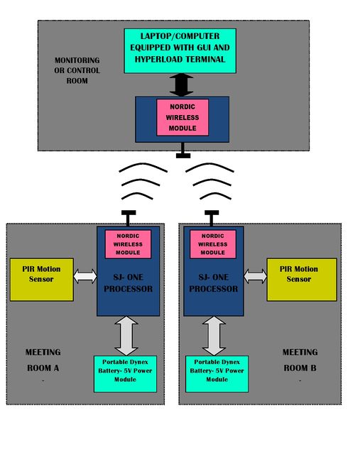
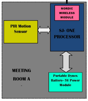
The system diagram evidently shows that the project setup will be implemented with the help three separate rooms. One room will serve as a central monitoring or the server room while the other two rooms will be for meeting or conference sessions. Every meeting room will be equipped with an interface of a SJ-ONE microcontroller and a PIR sensor.
The interface is powered with the help of a 5V portable Dynex power unit which will be connected to the SJ-ONE board with the help of a simple USB to min-USB cable. The monitoring room will consist of a laptop-SJ One microcontroller interfaced setup which will help us obtain and analyze the motion detection values and deduce any movement that occurs in the room from it.
The PIR motion sensors will detect movement in the meeting rooms and accordingly communicate with the central SJ-One board through the on-board Nordic Wireless modules on each SJ-One board. Once the data is received, it will be updated on the GUI(WPF on Laptop) that has records of all the meeting rooms that are currently or had been occupied. The user can monitor this data and keep track of all the rooms being occupied , hence , eliminating need of manually verifying the occupancy of every meeting room of a certain building or structure.
The design and implementation of the project has been divided into sections pertaining to hardware and software design as given below:
Hardware Design
PIR Motion Sensor
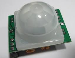
PIR Motion Sensor plays the primary role of detecting motion in the vicinity, in this case,a room. It relies on heat changes in the environment by using temperature variations as an indicator. The sensor has 3 pins: Vcc, GND and a GPIO which can be used while interfacing with a micro-controller. Detection takes place in conical area(~120 degrees) in front of the sensor and the range is approximately 30 feet. This device is power compatible with 3.3V/500uA and 5V/800uA as well and will be interfaced with each of the SJ-One boards that are being used in this project.
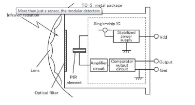
Internally, the PIR sensor consists of a crystal which is sensitive to IR radiation of particular frequency, which is emitted by heated objects. It uses a lens to focus this IR radiation onto the crystal. output signal from this crystal is given to an amplifier and comparator circuit. This makes the output available in digital form.
Nordic Wireless Module
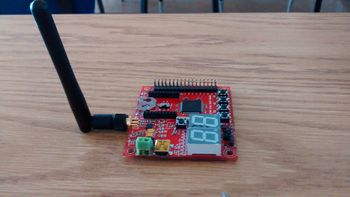
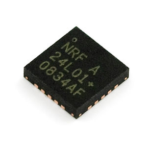
The Nordic module is an on-board wireless module which is configured to initiate wireless data transfers. Here, the modules are implemented with the purpose of establishing wireless communication with other SJ-One boards which will help send and receive the PIR sensor data resulting from motion detection. Nordic wireless module uses RF transmission with 2.4GHz ISM band. Along with RF transmission, it has a significant feature of operating at ultra-low power range of 1.9-3.6 V supply voltage (with 5 V tolerant pins) and 11.3mA Tx with 1mW output power.
Portable Dynex 5 V battery
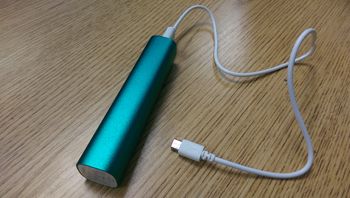
Every SJ-One board in the meeting rooms is powered by using 5 V portable Dynex battery. It can be interfaced with the board using the USB 3.0 to mini USB converter cable. This device is power compatible with the SJ-One board since with input specs of 5V/1000mA and output specs of 5V/1000mA. Charging power of this device can range upto 2200mAh. It is easy to charge, not so expensive and eliminates the need for separate power supply module design. Also makes the entire hardware assembly modular.
Hardware Interface
The hardware interfacing required for this project is significantly less since only the external PIR sensors need to be interfaced to the SJ-ONE board. The Nordic transceiver is an on-board module responsible for wireless transmission. The details of wireless transmission and mesh networks is also described in this section.
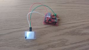
SJ-ONE and PIR Sensor Interface
The interfacing of PIR sensor with the SJ-One board is fairly simple as it involves only 3 connecting wires and pins namely : Vcc, GPIO and GROUND, as explained in the hardware design section. The details have been provided below for clarification:
| SJ-ONE | PIR Motion Sensor |
|---|---|
| VCC (5V) | VCC (5V) |
| GND | GND |
| P1.20 | OUT |
Software Design
The project has been divided into three sub modules for software design. The three main components of this system are -
- Slave Node
- Master Node
- Master Display App
Slave Node
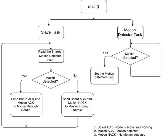
This is the node which monitors the PIR sensor for traces of activity. Whenever the PIR detects activity for a set number of times, the slave sends a Nordic message to master indicating that the room it is located in is now active. If the PIR sensor gives no activity signal for some time, the slave sends a message to the master saying the room is no longer in use and can be occupied.
Slave Node Flowchart
Master Node
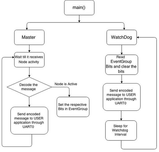
A Master node is the SjOne board that receives all the messages from the active nodes. All salve nodes, transmit their Nordic messages to his particular node. This board continuously monitors the Nordic channel to check for any messages. Whenever any new message is received, a status message is sent to the display app to update its UI accordingly. It also has a watchdog task which periodically checks if the known nodes are still active.
Master Node Flowchart
Master Display App
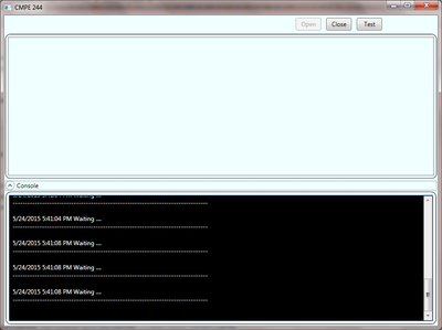
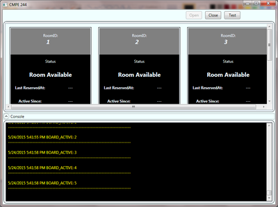
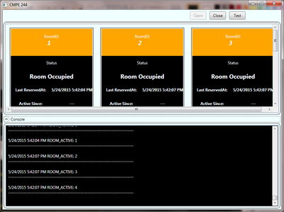
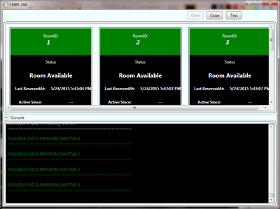
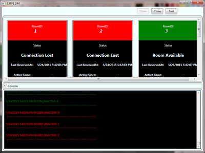
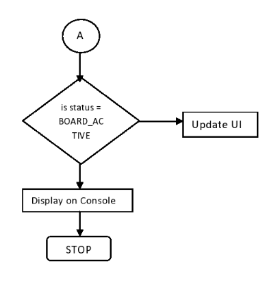
To provide a better user interface for this project, we decided to create a small app to display the latest status of Meeting room activity in easy to understand intuitive UI. This app was developed using C# .Net and WPF framework. It can also be replaced by a mobile app in future. It is similar to a hyperload terminal but looks cooler. Here are a few screenshots of the application in action -
Each status has been color coded for easy readability. The Master Display app monitors the master receiving node for the following statuses -
| Status | Description | Colour Code |
|---|---|---|
| BOARD_ACTIVE | The master has discovered a new node which just communicated with it.
This board is still functional. |
Gray |
| ROOM_ACTIVE | Some Activity has been detected in this room. It must be occupied. | Orange |
| ROOM_INACTIVE | No activity in room. It can be occupied. | Green |
| BOARD_INACTIVE | Connection has been lost with board. It was active some time ago. | Red |
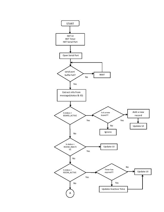
Master Display App Flowchart
Future Enhancements
The project can be modified in future by incorporating the following changes -
- Centralised reservation of meeting rooms through the Master Display App
- Interfacing of meeting room equipment such as lights, projectors, curtains to slave node
- Master display app can be designed as web enabled mobile based app which can be accessed on the go.
Testing & Technical Challenges
We faced a few minor problems in course of this project. They are classifed as hardware related and software related and listed below
Hardware Interfacing
PIR Sensor Reliability:
Some sensors were not giving reliable output. We tried tuning them by adjusting their sensitivity and the time period for which it remains high after detecting motion. Our observation was that sensors from Radioshack (which did not have these adjustments) were more reliable.
Software Design
Interrupt Or Polling?
We tried the hardware interface using interrupts as well. However the number of false positives increased in interrupts. This did not provide much reliable information to the master. So we decided to use the polling approach where we sent a Nordic message to the master only if the sensor output was consistent for some count. This did add a little overhead to the slave board, but it provided much better results. There was no other task the slave was running so we went for the polling approach.
Message Loss between Master Node and Control App:
We designed an application that communicated with SJOne board through serial port. In our application, we handled the data transmitted through UART0 port of SJOne master board. Because the Each type of message had different size (in bytes/chars), some part of messages was getting lost. As a result the control app was not updating the display. We solved this by padding each message with extra chars so that they were of the same size. Then we configured the master app to trigger an event to handle the data once we received at least two messages.
Conclusion
Nordic wireless provides a good alternative for wireless communications. It is sufficiently reliable to send small messages over moderate distances. We were able to achieve our project goal by using Nordic wireless protocol. We learnt how to interface sensors with MCU and read their values. We also learned how to write low level software to interact with hardware. By applying the freeRtos knowledge we gained in class, we were able to put together a system consisting of various modules to act in sync to achieve project objective.
Project Video
https://www.youtube.com/watch?v=UuTkoERGbB8
Project Source Code
References
References Used
List any references used in project.
http://socialledge.com/docs/wireless_8h.html
http://www.socialledge.com/sjsu/index.php?title=Low_Powered_Mesh_Network_stack
