Difference between revisions of "S24: Team Falcons"
(→Project Title) |
(→Software Design) |
||
| (46 intermediate revisions by the same user not shown) | |||
| Line 1: | Line 1: | ||
| − | [[File:Team logo.png |thumb| | + | [[File:Team logo.png |thumb|500px|caption|middle|Falcon's RC]] |
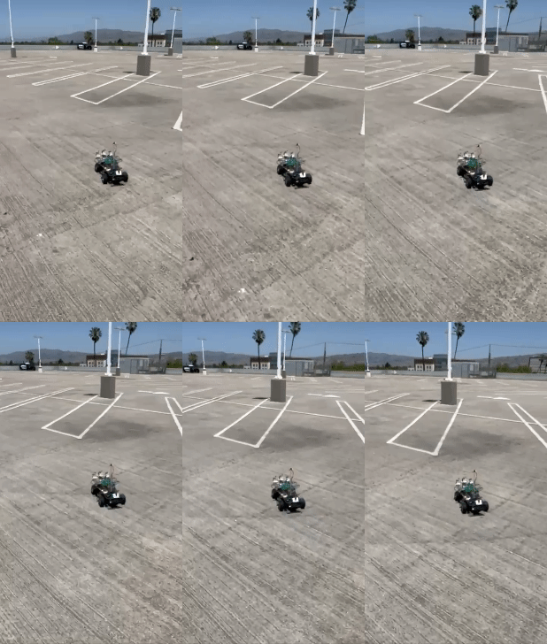
[[File:falcon_gif.gif|right|thumb|400px| Falcons]] | [[File:falcon_gif.gif|right|thumb|400px| Falcons]] | ||
| − | |||
| − | [[File:car_image.jpeg|left| | + | = Falcon = |
| + | |||
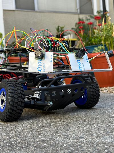
| + | [[File:car_image.jpeg|left|400px|thumb|Front view of the car]] | ||
| + | |||
| + | |||
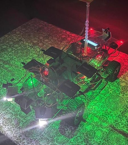
[[File:night_view.jpeg|center|450px|thumb|View at night]] | [[File:night_view.jpeg|center|450px|thumb|View at night]] | ||
| + | |||
| + | <br> | ||
| + | <HR> | ||
| + | <BR/> | ||
== Abstract == | == Abstract == | ||
| Line 23: | Line 30: | ||
<div><ul> | <div><ul> | ||
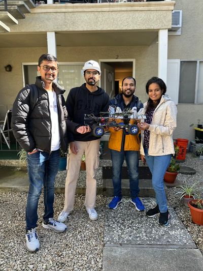
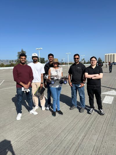
| − | <li style="display: inline-block;">[[File:falcon_team_pic.jpeg|thumb| | + | <li style="display: inline-block;">[[File:falcon_team_pic.jpeg|thumb|400px|caption|left|Team Picture]] </li> |
| − | <li style="display: inline-block;">[[File:falcon_with_preet.jpeg|thumb| | + | <li style="display: inline-block;">[[File:falcon_with_preet.jpeg|thumb|400px|caption|right|Team Picture with '''Preet''']]</li> |
</ul></div> | </ul></div> | ||
| − | Gitlab Project Link - https://gitlab.com/jincyjose491/sjtwo-c[https://gitlab.com/jincyjose491/sjtwo-c] | + | '''Gitlab Project Link''' - https://gitlab.com/jincyjose491/sjtwo-c[https://gitlab.com/jincyjose491/sjtwo-c] |
<BR/> | <BR/> | ||
| − | * Sensor | + | [[File:self_rc.jpeg|200px|middle]] |
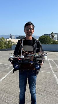
| − | ** | + | *'''''[https://www.linkedin.com/in/vatsal-ramani-609700164// Vatsal Ramani]''''' '''''[https://gitlab.com/jincyjose491/sjtwo-c/-/tree/feature/project_v1/projects/SENSOR_NODE?ref_type=heads GitLab]''''' |
| − | ** | + | ** '''Sensor Controller''' |
| + | ** '''Bridge Communication Controller''' | ||
| + | ** '''Android Application''' | ||
| + | [[File:Jincy_rc.jpeg|200px|middle]] | ||
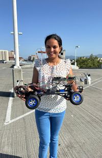
| + | *'''''[https://www.linkedin.com/search/results/all/?fetchDeterministicClustersOnly=true&heroEntityKey=urn%3Ali%3Afsd_profile%3AACoAAC1KIS8BlO9atVdL2s0wS-Za8qDrGTTopO8&keywords=jincy%20jose%20thottathil&origin=RICH_QUERY_SUGGESTION&position=0&searchId=7e6bcf26-b2f3-48be-b9c5-6426df353216&sid=RZp&spellCorrectionEnabled=false// Jincy Jose Thottathil]''''' '''''[https://gitlab.com/jincyjose491/sjtwo-c/-/tree/feature/project_v1/projects/driver?ref_type=heads?ref_type=heads GitLab]''''' | ||
| + | ** '''Driver Controller''' | ||
[[File:Shubham_Kumar_Savita.jpeg|200px|middle]] | [[File:Shubham_Kumar_Savita.jpeg|200px|middle]] | ||
*'''''[https://www.linkedin.com/in/shubhamks/ Shubham Kumar Savita]''''' '''''[https://gitlab.com/jincyjose491/sjtwo-c/-/tree/feature/project_v1/projects/motor/l5_application?ref_type=heads GitLab]''''' | *'''''[https://www.linkedin.com/in/shubhamks/ Shubham Kumar Savita]''''' '''''[https://gitlab.com/jincyjose491/sjtwo-c/-/tree/feature/project_v1/projects/motor/l5_application?ref_type=heads GitLab]''''' | ||
| − | ** Motor Controller | + | ** '''Motor Controller''' |
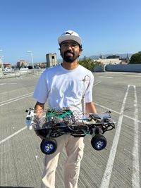
| − | + | [[File:Nav_rc.jpeg|200px|middle]] | |
| − | * | + | *'''''[https://www.linkedin.com/in/navaneeth-paliath-a21789110 Navaneeth Paliath]''''' '''''[https://gitlab.com/jincyjose491/sjtwo-c/-/tree/feature/project_v1/projects/geo_controller?ref_type=heads GitLab]''''' |
| − | * | + | * '''Geographical Controller''' |
| − | |||
| − | |||
| − | |||
| − | |||
| − | |||
| − | |||
| − | |||
| − | |||
| − | |||
| − | |||
<HR> | <HR> | ||
| Line 288: | Line 290: | ||
=== Hardware Design === | === Hardware Design === | ||
We connected 4 CAN transceivers to form the CAN bus as shown below. Since the transceivers already had termination resistors, we did not use any additional resistor. | We connected 4 CAN transceivers to form the CAN bus as shown below. Since the transceivers already had termination resistors, we did not use any additional resistor. | ||
| + | |||
| + | [[File:system_arch.gif|800px|center|thumb|High Level System Design]] | ||
| + | |||
<h4>PCB Schematic</h4> | <h4>PCB Schematic</h4> | ||
[[File:falcon_CAN.jpeg|center|thumb|300px| Falcons CAN Bus]] | [[File:falcon_CAN.jpeg|center|thumb|300px| Falcons CAN Bus]] | ||
| − | |||
=== DBC File === | === DBC File === | ||
| − | + | [https://gitlab.com/jincyjose491/sjtwo-c/-/blob/feature/project_v1/dbc/project.dbc Project DBC] | |
<pre> | <pre> | ||
| Line 408: | Line 412: | ||
== Sensor Controller ECU == | == Sensor Controller ECU == | ||
| − | *'''''[https://gitlab.com/jincyjose491/sjtwo-c/-/tree/feature/project_v1/projects/SENSOR_NODE?ref_type=heads/ GitLab Link :Sensor Controller]<br> ''''' | + | *'''''[https://gitlab.com/jincyjose491/sjtwo-c/-/tree/feature/project_v1/projects/SENSOR_NODE?ref_type=heads/ GitLab Link : Sensor Controller]<br> ''''' |
==== Component selection ==== | ==== Component selection ==== | ||
| Line 498: | Line 502: | ||
== Motor ECU == | == Motor ECU == | ||
| − | *'''''[https://gitlab.com/jincyjose491/sjtwo-c/-/tree/feature/project_v1/projects/motor/l5_application?ref_type=heads GitLab Link :Motor Controller]<br> ''''' | + | *'''''[https://gitlab.com/jincyjose491/sjtwo-c/-/tree/feature/project_v1/projects/motor/l5_application?ref_type=heads GitLab Link : Motor Controller]<br> ''''' |
=== Overview === | === Overview === | ||
| Line 531: | Line 535: | ||
Software Flow Diagram | Software Flow Diagram | ||
| − | |||
| − | |||
| − | |||
* Periodic callback functions running code modules periodically: | * Periodic callback functions running code modules periodically: | ||
** Periodic callback initialize: | ** Periodic callback initialize: | ||
| Line 641: | Line 642: | ||
servo_motor__change_steering_angle(motor_commands->MOTOR_CMD_steering); | servo_motor__change_steering_angle(motor_commands->MOTOR_CMD_steering); | ||
} | } | ||
| + | } | ||
| + | |||
| + | * RPM Initialize and get raw values | ||
| + | |||
| + | void rpm_sensor_init(void) { | ||
| + | lpc_peripheral__turn_on_power_to(LPC_PERIPHERAL__TIMER2); | ||
| + | LPC_TIM2->IR |= 0x3F; // resetting interrupts from 0-5 bits by setting them to 1. | ||
| + | LPC_TIM2->CCR = (1 << 1) | (1 << 2); // TC captured in CR0 on falling edge and interrupt is generated | ||
| + | lpc_peripheral__enable_interrupt(LPC_PERIPHERAL__TIMER2, rpm_sensor_interrupt_handler, NULL); | ||
| + | // this gives 100KHz frequency of the timer (10us) | ||
| + | uint32_t prescalar_divider = 959; // (prescalar + 1) this gives the value 960 for ease of calculation | ||
| + | LPC_TIM2->PR = prescalar_divider; | ||
| + | LPC_TIM2->TCR |= (1 << 0); // Enable the Timer (TC) and Prescalar (PC) clocks for counting | ||
| + | LPC_TIM2->TC = 0; // Set the Timer Clock to 0 | ||
| + | gpio__construct_with_function(2, 6, 3); // Port 2.6, Function 3 for CAP | ||
| + | interrupt_count = 0; | ||
| + | rpm_readings = 0; | ||
| + | rpm_scalar = | ||
| + | (circumference_of_tire_cm * clock__get_peripheral_clock_hz()) / (spur_gear_ratio * (prescalar_divider + 1)); | ||
| + | } | ||
| + | float rpm__get_raw_values(void) { | ||
| + | /*100Khz = 100000 samples/sec, prescale counter is incremented | ||
| + | on every PCLK (pg.693 ref manual). TC is incremented when PCLK reaches the value | ||
| + | stored in Prescale register and Prescale Counter is reset the next clock cycle of PCLK*/ | ||
| + | const uint32_t timer_counter_upper_bound = 100000; // (96 MHZ/ 959+1); 959 is perscaler divider | ||
| + | const uint32_t timer_capture_value = LPC_TIM2->CR0; | ||
| + | const uint32_t timer_counter_value = LPC_TIM2->TC; | ||
| + | if (timer_counter_value > timer_counter_upper_bound || timer_capture_value == 0) { | ||
| + | // speed_in_kph = 0.0f; | ||
| + | speed_in_rpm = 0.0f; | ||
| + | } else { | ||
| + | // speed_in_kph = kph_scalar / timer_capture_value; | ||
| + | speed_in_rpm = rpm_scalar / timer_capture_value; | ||
| + | // printf("timer_capture_value: %ld\n", timer_capture_value); | ||
| + | } | ||
| + | // printf("speed in rpm: %f\n", speed_in_rpm); | ||
| + | speed_in_kph = (speed_in_rpm * ((float)3600 / (float)100000)); | ||
| + | // printf("speed in kph: %f\n", speed_in_kph); | ||
| + | return speed_in_rpm; | ||
} | } | ||
| Line 1,004: | Line 1,044: | ||
== Communication Bridge Controller == | == Communication Bridge Controller == | ||
| − | *'''''[https://gitlab.com/jincyjose491/sjtwo-c/-/tree/feature/project_v1/projects/SENSOR_NODE/ GitLab Link :Bridge Controller]<br> ''''' | + | *'''''[https://gitlab.com/jincyjose491/sjtwo-c/-/tree/feature/project_v1/projects/SENSOR_NODE/ GitLab Link : Bridge Controller]<br> ''''' |
The bridge controller aims to communicate with the Android application, receiving GPS coordinates to initiate vehicle movement and essential debug information for field testing. The user selects the final destination on Google Maps via the Android application, directing the car to navigate to the specified location. | The bridge controller aims to communicate with the Android application, receiving GPS coordinates to initiate vehicle movement and essential debug information for field testing. The user selects the final destination on Google Maps via the Android application, directing the car to navigate to the specified location. | ||
| Line 1,134: | Line 1,174: | ||
== Conclusion == | == Conclusion == | ||
| − | |||
| − | + | The RC car project was a great opportunity to gain more embedded software and hardware skills. It also allowed us to showcase our technical proficiency and teamwork. The entire project was divided into 4 sections and specific task for each of the topics were curated during the initial weeks. The tasks were completed in a timely manner and the technical challenges were solved as a team, resulting in a successful demo where the RC car navigated itself to a defined destination avoiding all obstacles on its path. Along the journey, we learnt industry relevant skills such as unit test framewroks, test driven development, CAN communication and DBC files. The project also helped us get a firm understanding of the communication protocols and hardware development. | |
| + | |||
| + |
This project has been a tremedous educational journey. Though this journey had many ups and downs, the team collaboration and grit played a crucial role in ensuring the project was successful. The practical insights and hands-on learning we gained from this project far surpass any technical skills we might have acquired through theoretical learning. | ||
=== Project Video === | === Project Video === | ||
| + | |||
| + | '''https://www.youtube.com/watch?v=W4M5YtxNGBo | ||
=== Project Source Code === | === Project Source Code === | ||
| + | ''' [https://gitlab.com/jincyjose491/sjtwo-c/-/tree/master/projects/SENSOR_NODE?ref_type=heads/ Falcon's GitLab ]''' | ||
=== Advise for Future Students === | === Advise for Future Students === | ||
| Line 1,156: | Line 1,200: | ||
=== Acknowledgement === | === Acknowledgement === | ||
| − | We would like to thank our instructor, Preet, for | + | We would like to thank our instructor, Preet, for his effort, motivation, and guidance. We also appreciate the support from ISA volunteers Kyle and Ninaad. Preet's dedication has significantly contributed to our understanding of unit testing, C coding, software-hardware integration, teamwork, Git, and documentation. |
| − | We also | + | We would also like to acknowledge all the teams who came before us, as their reports provided a lot of insights about the project. |
=== References === | === References === | ||
| + | |||
| + | 1. [http://socialledge.com/sjsu/index.php/Industrial_Application_using_CAN_Bus Past RC Wiki Projects] | ||
| + | <BR> | ||
| + | 2. [https://maxbotix.com/pages/lv-maxsonar-ez-datasheet Ultrasonic Range Finder Datasheet] | ||
| + | <BR> | ||
| + | 3. [https://traxxas.com/support/Programming-Your-Traxxas-Electronic-Speed-Control ESC Calibration] | ||
| + | <BR> | ||
| + | 4. [http://www.instructables.com/id/ESC-Programming-on-Arduino-Hobbyking-ESC/ ESC PWM information] | ||
| + | <BR> | ||
| + | 5. [https://forums.traxxas.com/showthread.php?8923102-PWM-in-XL-5 ESC XL-5 PWM information] | ||
| + | <BR> | ||
| + | 6. [https://www.movable-type.co.uk/scripts/latlong.html GEO Bearing information] | ||
| + | <BR> | ||
| + | 7. [https://cdn-learn.adafruit.com/downloads/pdf/adafruit-ultimate-gps.pdf GPS Module datasheet] | ||
| + | <BR> | ||
| + | 8. [https://www.digikey.com/en/maker/projects/how-to-calibrate-a-magnetometer/50f6bc8f36454a03b664dca30cf33a8b Compass calibration] | ||
| + | <BR> | ||
Latest revision as of 06:23, 25 May 2024
Contents
Falcon
Abstract
The Falcon RC car project is the combined efforts of our team to create an autonomously RC Car that avoids all obstacles and follow GPS to reach the destination. Here, we have put in all our experience in software design, hardware design, unit testing, power systems, and mobile application development. Project development started in March of 2024 and ended in May 2024.
Introduction
The project was divided into 4 modules:
- Sensor and Bridge Controller
- Driver Controller
- Geo Controller
- Motor Controller
Driver controller is the master controller that receive inputs from sensor controller and geo controller, and gives output commands to motor controller. The destination coordinate is send from Android application to sensor node via Bluetooth. The app also send a hard start and stop to the car. The car starts only on receiving start signal from the app and stops completely on receiving stop signal from app.
Team Members & Responsibilities
Gitlab Project Link - https://gitlab.com/jincyjose491/sjtwo-c[1]
- Vatsal Ramani GitLab
- Sensor Controller
- Bridge Communication Controller
- Android Application
- Jincy Jose Thottathil GitLab
- Driver Controller
- Shubham Kumar Savita GitLab
- Motor Controller
- Navaneeth Paliath GitLab
- Geographical Controller
Schedule
| Week# | Start Date | End Date | Task | Status |
|---|---|---|---|---|
| 1 | 02/22/2024 | 02/26/2024 |
|
Completed |
| 2 | 02/26/2024 | 03/10/2024 |
|
Completed |
| 3 | 03/10/2024 | 03/12/2024 |
|
Completed |
| 4 | 03/12/2024 | 03/19/2024 |
|
Completed |
| 5 | 03/19/2024 | 03/26/2024 |
|
Completed |
| 6 | 03/26/2024 | 04/02/2024 |
|
Completed |
| 7 | 04/02/2024 | 04/09/2024 |
|
Completed |
| 8 | 04/09/2024 | 04/16/2024 |
|
Completed |
| 9 | 04/16/2024 | 04/23/2024 |
|
Completed |
| 10 | 04/23/2024 | 04/30/2024 |
|
Completed |
| 11 | 04/30/2024 | 05/07/2024 |
|
Completed |
Parts List & Cost
| Item# | Part Desciption | Vendor | Qty | Cost |
|---|---|---|---|---|
| 1 | RC Car | Traxxas | 1 | $265.00 |
| 2 | SJ2 boards | CMPE SCE | 4 | $50.00 each |
| 3 | CAN Transceivers | Adafruit [2] | 4 | $3.95 each |
| 4 | Ultrasonic sensor | Adafruit [3] | 4 | $114.00 |
| 5 | GPS PA1616S BREAKOUT | Digikey [4] | 1 | $29.95 |
| 6 | LSM303AGR ACC COMPASS | Digikey [5] | 1 | $12.50 |
| 7 | LCD Display | Amazon [6] | 1 | $12.99 |
| 8 | RPM sensor | Traxxas [7] | 1 | $12.00 |
Printed Circuit Board
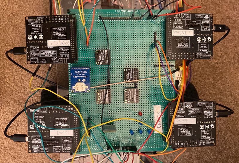
PCB Schematic
CAN Communication
The 4 nodes in our project communicated through CAN bus. Every nodes communicated in a frequency of 10Hz. For the speed of our car and all algorithms to work, the optimum frequency in periodic scheduling was found out to be 10Hz.
Hardware Design
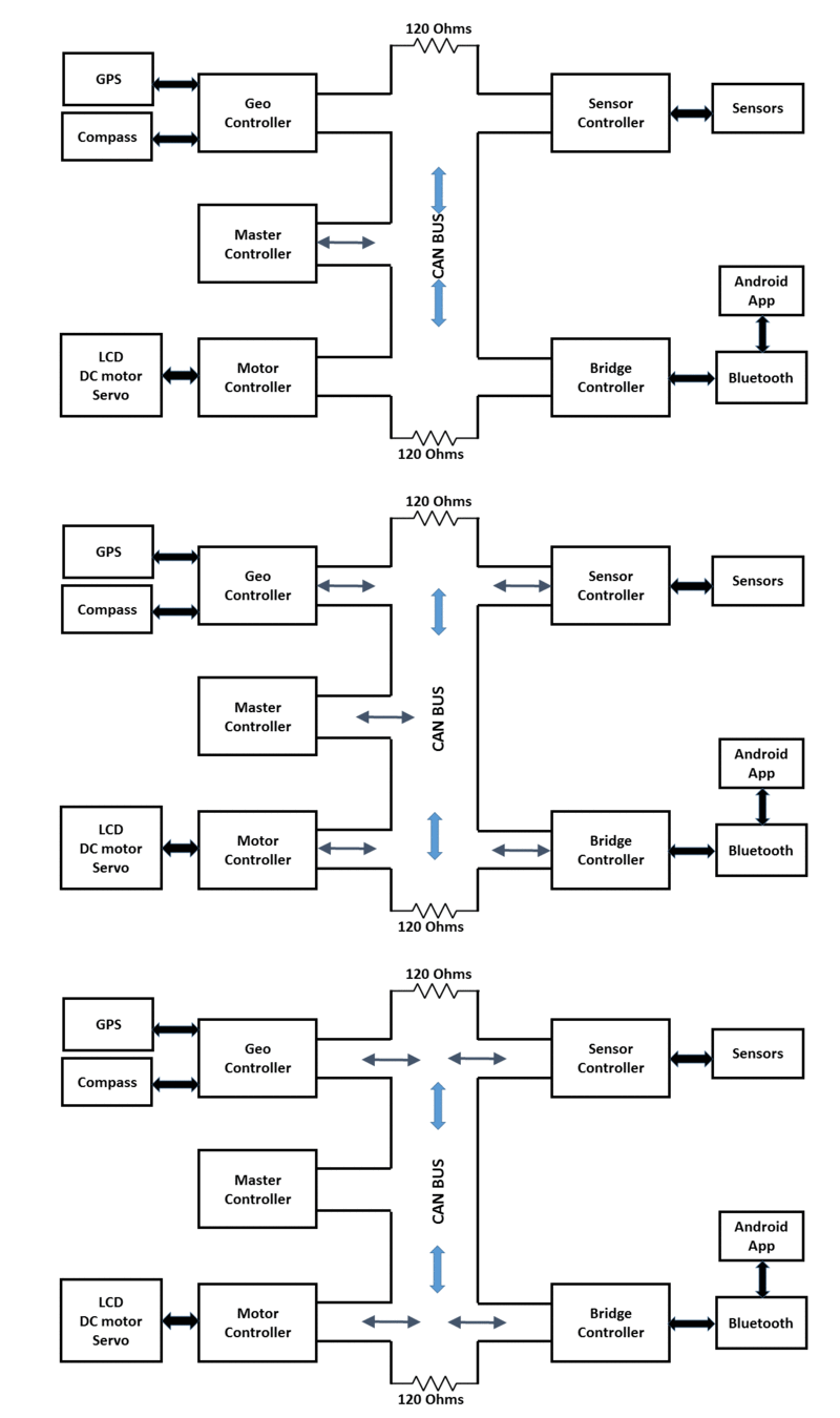
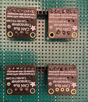
We connected 4 CAN transceivers to form the CAN bus as shown below. Since the transceivers already had termination resistors, we did not use any additional resistor.
PCB Schematic
DBC File
VERSION ""

NS_ :
	BA_
	BA_DEF_
	BA_DEF_DEF_
	BA_DEF_DEF_REL_
	BA_DEF_REL_
	BA_DEF_SGTYPE_
	BA_REL_
	BA_SGTYPE_
	BO_TX_BU_
	BU_BO_REL_
	BU_EV_REL_
	BU_SG_REL_
	CAT_
	CAT_DEF_
	CM_
	ENVVAR_DATA_
	EV_DATA_
	FILTER
	NS_DESC_
	SGTYPE_
	SGTYPE_VAL_
	SG_MUL_VAL_
	SIGTYPE_VALTYPE_
	SIG_GROUP_
	SIG_TYPE_REF_
	SIG_VALTYPE_
	VAL_
	VAL_TABLE_

BS_:

BU_: DBG DRIVER IO MOTOR SENSOR GEO


BO_ 100 DRIVER_HEARTBEAT: 1 DRIVER
 SG_ DRIVER_HEARTBEAT_cmd : 0|8@1+ (1,0) [0|0] "" SENSOR,MOTOR

BO_ 10 START_STOP: 1 SENSOR
 SG_ START_STOP_cmd : 0|8@1+ (1,0) [0|1] "cmd" MOTOR

BO_ 200 SENSOR_SONARS: 5 SENSOR
 SG_ SENSOR_SONARS_left : 0|10@1+ (1,0) [0|500] "cm" DRIVER
 SG_ SENSOR_SONARS_right : 10|10@1+ (1,0) [0|500] "cm" DRIVER
 SG_ SENSOR_SONARS_middle : 20|10@1+ (1,0) [0|500] "cm" DRIVER
 SG_ SENSOR_SONARS_rear : 30|10@1+ (1,0) [0|500] "cm" DRIVER

BO_ 210 GEO_STATUS: 8 GEO
  SG_ GEO_STATUS_COMPASS_HEADING : 0|10@1+ (1,0) [0|359] "Degrees" DRIVER, SENSOR
  SG_ GEO_STATUS_COMPASS_BEARING : 10|10@1+ (1,0) [0|359] "Degrees" DRIVER, SENSOR
  SG_ GEO_STATUS_DISTANCE_TO_DESTINATION : 20|16@1+ (0.1,0) [0|1500] "Meters" DRIVER, SENSOR
  SG_ GEO_STATUS_BEARING_ANGLE_TO_CHKPT : 36|10@1+ (1,0) [0|359] "Degrees" DRIVER, SENSOR
  SG_ GEO_STATUS_DISTANCE_TO_CHKPT : 46|16@1+ (1,0) [0|1500] "Meters" DRIVER, SENSOR
  SG_ GEO_STATUS_GPS_LOCK_ACQUIRED : 62|1@1+ (1,0) [0|0] "Boolean" DRIVER, SENSOR

BO_ 250 GPS_DESTINATION_LOCATION: 8 SENSOR
 SG_ GPS_DEST_LATITUDE_SCALED : 0|32@1- (1,0) [-90000000|90000000] "Degrees" GEO
 SG_ GPS_DEST_LONGITUDE_SCALED : 32|32@1- (1,0) [-180000000|1800000000] "Degrees" GEO

BO_ 300 MOTOR_CMD: 2 DRIVER
 SG_ MOTOR_CMD_steering : 0|8@1- (1,0) [-45|45] "degree" MOTOR
 SG_ MOTOR_CMD_movement : 8|8@1- (0.1,0) [-10|10] "kph" MOTOR

BO_ 400 MOTOR_RPM_SENSOR_DATA: 1 MOTOR
 SG_ RPM_SPEED: 0|8@1+ (0.1,0) [0|10] "kph" DRIVER, SENSOR

BO_ 500 MOTOR_STATUS: 2 MOTOR
 SG_ MOTOR_STATUS_steering : 0|8@1- (1,0) [-45|45] "degree" DRIVER
 SG_ MOTOR_STATUS_movement : 8|8@1- (0.1,0) [-6|6] "kph" DRIVER

BO_ 510 DBG_DRIVER: 3 DRIVER
 SG_ driver_intention : 0|8@1+ (1,0) [0|0] "" DBG
 SG_ driver_steer_direction : 8|8@1+ (1,0) [0|0] "" DBG
 SG_ driver_drive_direction : 16|8@1+ (1,0) [0|0] "" DBG

BO_ 800 DEBUG_GEO_COORDS_CURRENT: 8 GEO
 SG_ DEBUG_GEO_GPS_CURRENT_LAT_SCALED : 0|32@1- (1,0) [-90000000|90000000] "Degrees" DRIVER, SENSOR
 SG_ DEBUG_GEO_GPS_CURRENT_LON_SCALED : 32|32@1- (1,0) [-180000000|1800000000] "Degrees" DRIVER, SENSOR

BO_ 801 DEBUG_GEO_COORDS_CHKPT: 8 GEO
 SG_ DEBUG_GEO_GPS_CHKPT_LAT_SCALED : 0|32@1- (1,0) [-90000000|90000000] "Degrees" DRIVER, SENSOR
 SG_ DEBUG_GEO_GPS_CHKPT_LON_SCALED : 32|32@1- (1,0) [-180000000|1800000000] "Degrees" DRIVER, SENSOR

CM_ BU_ DRIVER "The driver controller driving the car";
CM_ BU_ MOTOR "The motor controller of the car";
CM_ BU_ SENSOR "The sensor controller of the car";
CM_ BU_ GEO "The geo controller of the car";
CM_ BO_ 100 "Sync message used to synchronize the controllers";
CM_ SG_ 100 DRIVER_HEARTBEAT_cmd "Heartbeat command from the driver";

BA_DEF_ "BusType" STRING ;
BA_DEF_ BO_ "GenMsgCycleTime" INT 0 0;
BA_DEF_ SG_ "FieldType" STRING ;

BA_DEF_DEF_ "BusType" "CAN";
BA_DEF_DEF_ "FieldType" "";
BA_DEF_DEF_ "GenMsgCycleTime" 0;

BA_ "GenMsgCycleTime" BO_ 100 1000;
BA_ "GenMsgCycleTime" BO_ 200 50;
BA_ "FieldType" SG_ 100 DRIVER_HEARTBEAT_cmd "DRIVER_HEARTBEAT_cmd";

VAL_ 100 DRIVER_HEARTBEAT_cmd 2 "DRIVER_HEARTBEAT_cmd_REBOOT" 1 "DRIVER_HEARTBEAT_cmd_SYNC" 0 "DRIVER_HEARTBEAT_cmd_NOOP" ;
Sensor Controller ECU
Component selection
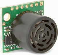
Selecting the appropriate sensor for an application is crucial. For this project, the sensor needs to be responsive, accurate, capable of operating in outdoor environments, and able to detect obstacles at long ranges. While there are numerous distance measurement options available, we have used MaxBotix (MB1010 LV EZ1) for all the positions. Initially we were thinking to use ultrasonic transducers sensors, but since it needs to have time measurement between the transmitted trigger signal and received echo which was complex software logic, it got ruled out. Maxbotix sensors have easy-to-use output formats and low power consumption of 2 mA for 3v power.
Hardware Design
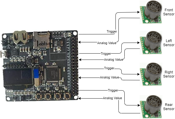
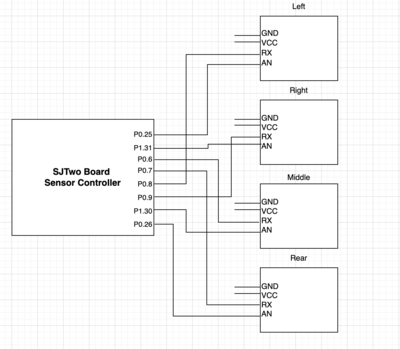
Sensors are interfaced with combination of GPIO, ADC and other pins of the SJTwo board.
Sensor pin configuration to SJTwo board
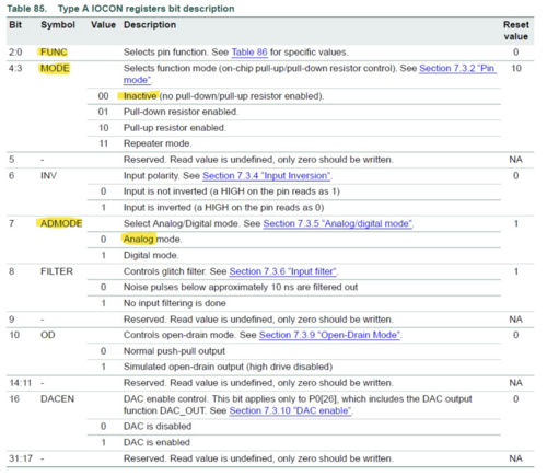
The sensor interface made use of onboard ADC (analog to digital converter) pins because we were utilizing the analog output of Maxbotix sensors. LPC 408x has a 12-cycle progressive approximation analog to a digital converter. These ADC have been designed to read sensor readings on a size of 4096 counts. To utilize sjtwo pins as ADC with better sign precision, there was the extra change expected in default ADC drivers which require disabling pull-up and pull-down resistors from the IOCON register of each ADC initialization. Maxbotix sensors need to get set off by logic high pulse on their Rx Pin, this has been executed by setting a proper trigger pin as GPIO output. By doing IOCON configurations specific to the ADC channel, selection of analog mode, and disabling pull-up, and pull-down mode, sensor inputs were configured for 3 ADC channels and 1 DAC Channel which was configured as ADC by doing appropriate IOCON Selection.
|
Software Design
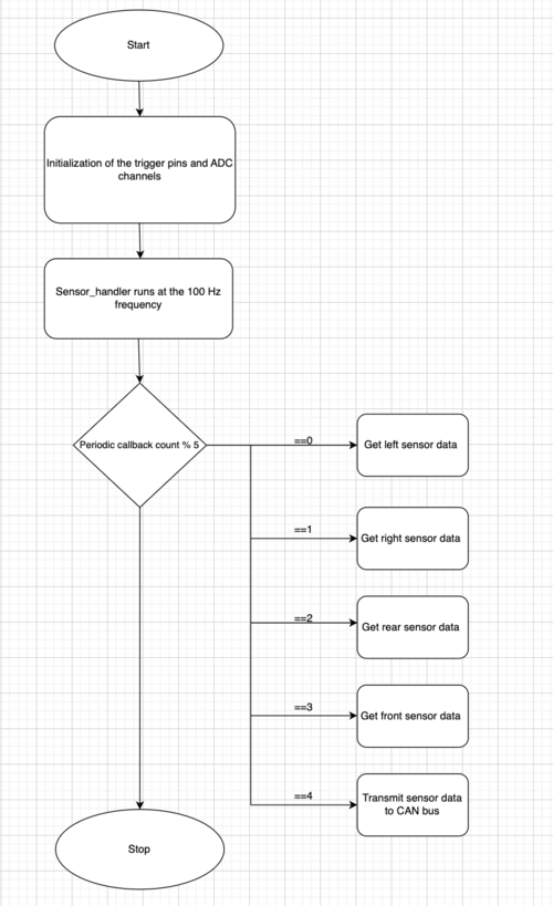
Created APIs to trigger sensors, get the readings and calculate distance (readings from sensors are just raw values not real distance in inches). To achieve minimal cross-talk and faster sensor reading, used 20 Hz periodic_callbacks. Sensors are getting triggered in the specific manner like Left -> Right -> Rear ->middle to reduce crosstalk between adjacent sensors and power consumption of sensors. With this order, a 10ms window was given to each sensor. Software should sample 32 sensor readings in a buffer that might contain any abrupt intermittent value which needs to be avoided. By sorting these sensor readings using a quick sorting algorithm, the median was considered as the final end reading for broadcasting over the CAN bus. All the sensor values are digitally converted in the range of 0 to 4096 (12 bit ADC). These values are converted to distance format in centimeter unit using formula conv_val = (raw_val * 0.3182) - 0.3959.
Technical Challenges
- Problem: Crosstalk between adjacent sensors when all sensors transmitting waves simultaneously
- Solution: Triggering sensors at different specific order and positioning sensors on the proper angles.
- Problem: Power Deficiency
- Solution: At first, when the sensors were tested individually (as well as together on early iterations of the car), they performed to specifications. However, when other subsystems were integrated into the car, the sensor feedback fluctuated wildly. Adding capacitor to the sensor pins was the crucial solution.
- Problem: After fixing the power issues, still there were fluctuations in the sensor data, thereby causing collision while testing obstacle avoidance.
- Solution: We created 3D mounts to place on the sensors head. Those mounts created the sonar waves to reflecting back to the sensor causing interference while testing. Thus removal of the 3D mounts helped to get better readings.
Motor ECU
Overview
The Motor ECU is the Motor Module, a dedicated SJTwo board that controls the motor and the servo. It communicates with the Driver Module over the CAN bus through motor commands sent by the driver and RPM data commands sent by the motor. The main functions include controlling forward, reverse, and neutral movement of the motor, left, right, and center movement of the servo, and receiving RPM signals for speed information. Additional functions necessary for the effective movement of the RC car include PID control, which utilizes the RPM sensor data to maintain the car's speed on different ramps and terrains.
Hardware Design
The hardware design consists of motor, servo and rpm sensor interfaced with GPIO PWM output and input for sensor pins of the SJTwo board.
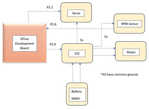
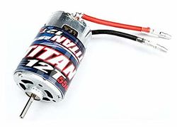
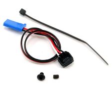
DC Motor and RPM Sensor
DC motor gets the PWM signal from the board IO pin P2.0 through Electronic Speed Control(ESC) which is also connected to the battery. Based on PWM signals power is delivered to the Motor through ESC. Since we had different dc motor installation than what was in the Traxxas rpm installation video we glued the RPM sensor at RPM sensor slot and fixed it with Motor cover after installing the spur gear and trigger magnet. installed
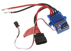
ESC
Electronic Speed Control(ESC) is a programmable device which controls the movement of brushless DC motor based on the input PWM signal provided to it through either receiver or through board (SJTwo board). ESC also outputs 5v Supply that we used for common connection between RPM and servo and made sure all the grounds are common during the project development. ESC gets input signal from board P2.0 which then controls the motor.
Servo
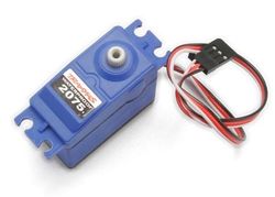
Servo motor is connected to P2.1 port of SJTwo board. It is used to control the front wheel for directions. Servo gets the power from ESC and signal from board to function.
Software Design
Software Flow Diagram
- Periodic callback functions running code modules periodically:
- Periodic callback initialize:
   can_motor_init();
   motor_initialize();
   rpm_sensor_init();
- Periodic callback 1Hz:
can_motor_reset();
- Periodic callback 100Hz:
   motor_neutral();
   motor_controller_manage_mia();
   rpm__get_raw_values();
   can_handler__transmit_messages();
   motor_controller_incoming_all_can_messages();
- Function definitions:
 void motor_drive_commands(dbc_MOTOR_CMD_s *motor_commands) {
 gpio__set(stop_right_tail_led);
 gpio__set(stop_left_tail_led);
 start_stop = can_handler__get_app_commands();
 if (start_stop == 0) {
   motor_neutral();
   gpio__set(stop_right_tail_led);
   gpio__set(stop_left_tail_led);
   current_drive_direction = DRIVE_NEUTRAL;
 } else {
   float target_speed = motor_commands->MOTOR_CMD_movement;
   if (target_speed == 6) {
     next_drive_direction = DRIVE_FORWARD;
   } else if (target_speed == 2) {
     target_speed = -7.0f; // reverse kph from driver
     next_drive_direction = DRIVE_REVERSE;
   } else if (target_speed == 0) {
     next_drive_direction = DRIVE_NEUTRAL;
   };
   switch (next_drive_direction) {
   case DRIVE_FORWARD:
     gpio__reset(stop_right_tail_led);
     gpio__reset(stop_left_tail_led);
     if (current_drive_direction != DRIVE_FORWARD) {
       if (current_drive_direction == DRIVE_NEUTRAL) {
         // motor__calculate_speed(target_speed);
         drive_forward();
         current_drive_direction = DRIVE_FORWARD;
       } else {
         // motor__calculate_speed(0);
         drive_forward();
         current_drive_direction = DRIVE_FORWARD;
       }
     } else {
       drive_forward();
       current_drive_direction = DRIVE_FORWARD;
     }
     break;
   case DRIVE_NEUTRAL:
     current_drive_direction = DRIVE_NEUTRAL;
     motor_neutral();
     gpio__set(stop_right_tail_led);
     gpio__set(stop_left_tail_led);
     break;
   case DRIVE_REVERSE:
     gpio__reset(stop_right_tail_led);
     gpio__reset(stop_left_tail_led);
     if (current_drive_direction != DRIVE_REVERSE) {
       if (current_drive_direction == DRIVE_NEUTRAL) {
         current_drive_direction = DRIVE_REVERSE;
         drive_reverse();
       } else if (current_drive_direction == DRIVE_REVERSE0) {
         current_drive_direction = DRIVE_NEUTRAL;
         motor_neutral();
       } else if (current_drive_direction == DRIVE_NEUTRAL0) {
         current_drive_direction = DRIVE_REVERSE0;
         drive_reverse();
       } else {
         current_drive_direction = DRIVE_NEUTRAL0;
         motor_neutral();
       }
     } else {
       drive_reverse();
       current_drive_direction = DRIVE_REVERSE;
       gpio__reset(stop_right_tail_led);
       gpio__reset(stop_left_tail_led);
     }
     break;
   default:
     current_drive_direction = DRIVE_NEUTRAL;
     motor_neutral();
     gpio__set(stop_right_tail_led);
     gpio__set(stop_left_tail_led);
     break;
   }
 }
}
- Steering Commands
 void servo_steer_commands(dbc_MOTOR_CMD_s *motor_commands) {
 start_stop = can_handler__get_app_commands();
 if (start_stop == 0) {
   steer_center();
   gpio__set(stop_right_tail_led);
   gpio__set(stop_left_tail_led);
 } else {
   servo_motor__change_steering_angle(motor_commands->MOTOR_CMD_steering);
 }
}
- RPM Initialize and get raw values
 void rpm_sensor_init(void) {
 lpc_peripheral__turn_on_power_to(LPC_PERIPHERAL__TIMER2);
 LPC_TIM2->IR |= 0x3F;                // resetting interrupts from 0-5 bits by setting them to 1.
 LPC_TIM2->CCR = (1 << 1) | (1 << 2); // TC captured in CR0 on falling edge and interrupt is generated
 lpc_peripheral__enable_interrupt(LPC_PERIPHERAL__TIMER2, rpm_sensor_interrupt_handler, NULL);
 // this gives 100KHz frequency of the timer (10us)
 uint32_t prescalar_divider = 959; // (prescalar + 1) this gives the value 960 for ease of calculation
 LPC_TIM2->PR = prescalar_divider;
 LPC_TIM2->TCR |= (1 << 0); // Enable the Timer (TC) and Prescalar (PC) clocks for counting
 LPC_TIM2->TC = 0;          // Set the Timer Clock to 0
 gpio__construct_with_function(2, 6, 3); // Port 2.6, Function 3 for CAP
 interrupt_count = 0;
 rpm_readings = 0;
 rpm_scalar =
     (circumference_of_tire_cm * clock__get_peripheral_clock_hz()) / (spur_gear_ratio * (prescalar_divider + 1));
}
float rpm__get_raw_values(void) {
 /*100Khz = 100000 samples/sec, prescale counter is incremented
  on every PCLK (pg.693 ref manual). TC is incremented when PCLK reaches the value
  stored in Prescale register and Prescale Counter is reset the next clock cycle of PCLK*/
 const uint32_t timer_counter_upper_bound = 100000; // (96 MHZ/ 959+1); 959 is perscaler divider
 const uint32_t timer_capture_value = LPC_TIM2->CR0;
 const uint32_t timer_counter_value = LPC_TIM2->TC;
 if (timer_counter_value > timer_counter_upper_bound || timer_capture_value == 0) {
   // speed_in_kph = 0.0f;
   speed_in_rpm = 0.0f;
 } else {
   // speed_in_kph = kph_scalar / timer_capture_value;
   speed_in_rpm = rpm_scalar / timer_capture_value;
   // printf("timer_capture_value: %ld\n", timer_capture_value);
 }
 // printf("speed in rpm: %f\n", speed_in_rpm);
 speed_in_kph = (speed_in_rpm * ((float)3600 / (float)100000));
 // printf("speed in kph: %f\n", speed_in_kph);
 return speed_in_rpm;
}
Technical Challenges
Don'ts:
- Always be aware and cautious of ESC connections before powering it up. Check and confirm all connections to the ESC two or three times before supplying power to it because it may burn or damage the internal components without warning, and it cannot be recovered. We had to purchase another one, and it was expensive.
- Problem: The ESC was going out of calibration, indicated by its yellow LED (or red LED if Low Power mode is enabled) toggling.
- Solution: Providing 3 seconds of neutral PWM to the motor through the ESC helped maintain calibration and stabilized the LED.
- Problem: The reverse transition was not happening immediately after forward, though forward was happening after reverse.
- Solution: The reverse has a specific sequence to function properly. We need to provide neutral -> reverse -> neutral -> reverse PWM signals to get it to work.
- Problem: The initial ESC boot-up sequence was not happening.
- Solution: Referring to multiple sources, specifically the user manual of the car, helped ensure the proper hold/press sequence for the ESC. We used the Traxxas model, and setting it to Mode-1/Training mode using the ESC button successfully set the ESC every time.
Geographical Controller
Geo controller: https://gitlab.com/jincyjose491/sjtwo-c/-/tree/master/projects/geo_controller?ref_type=heads
Navigation in modern systems seamlessly integrates GPS with compass technology to enhance driving experience and safety. GPS provides accurate location data by communicating with satellites, while the compass offers directional orientation of the vehicle. This combination is essential also in the RC car project as it enables the vehicle to autonomously maneuver to a given detsination coordinate. The GPS modules keeps track of the current position of the car, provides the direction that the car should move towards and the compass module keeps track of the direction in which the car is actually heading. Integrating the two modules, an algorithm has been developed as elaborated below to achieve the complete autonomous functionality.
Hardware Design
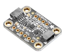
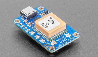
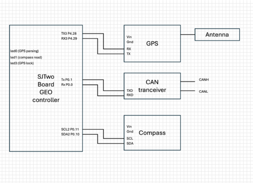
The Geo controller is interfaced to both the GPS module and the compass modules. Both these modules are powered using stable 3.3V inputs which are derived from the SJ Two boards. The GPS communicates with the board via UART and is connected to the controller at the P4.28 and P4.29, Rx and TX pins respectively. The GPS requires an antenna which is interfaced to the module via a UFL to SMA connector. Though the GPS module houses an led to indicate FIX on GPS lock, the led3 of SJTwo board was used to also show lock acquired after GPS string was received. The compass module communicates with the board via I2C and is connected at P0.10 SDA and P0.11 SCL pins respectively. As part of the hardware design, the compass module was mounted on a separate long pole, away from other interferences. The led1 of SJTwo board was used to indicate a successful comapss read.
Software Design
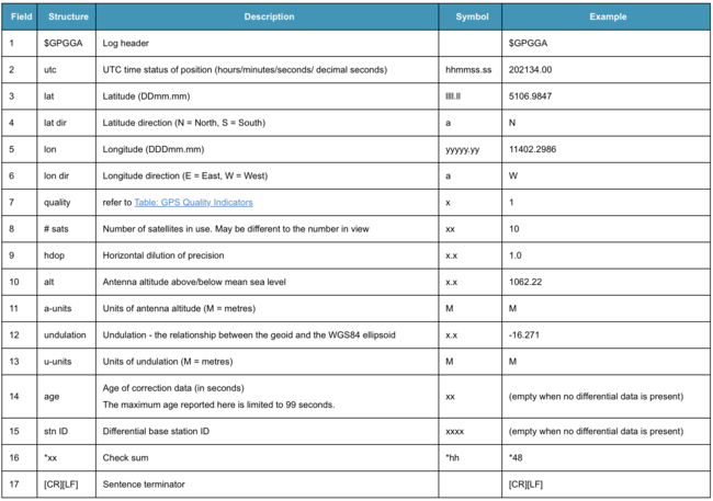
The GPS module provides data in the form of NMEA strings. NMEA (National Marine Electronics Association) is a standard protocol used by GPS receivers to transmit data. These strings contain various pieces of information, such as latitude, longitude, altitude, and time. The data bytes sent from the GPS module through UART are first loaded into a line buffer. The algorithm then parses this buffer to capture the specific $GPGGA strings that includes the correct position, time, and fix status. A GPS string example is given and the corresponding parameters in the string are discussed in the table below:
$GPGGA,202530.00,5109.0262,N,11401.8407,W,5,40,0.5,1097.36,M,-17.00,M,18,TSTR*61\r\n
Following is the GPS string parsing logic where the lattitude and longitude are retrieved:
static gps_coordinates_t gps_string_to_coordinates(char gps_line[line_buffer_size]) {
  gps_coordinates_t coordinates = {0, 0};
  char gps_line_copy[line_buffer_size];
  strcpy(gps_line_copy, gps_line);
  char *token = strtok(gps_line_copy, ",");
  int token_count = 0;
  char *tokens[6];
  while (token != NULL && token_count < 7) {
    if (token_count == 2 || token_count == 3 || token_count == 4 || token_count == 5 || token_count == 6) {
      tokens[token_count - 2] = token;
    }
    token = strtok(NULL, ",");
    token_count++;
  }

  // Check GPS Quality indicator value != 0 to see if FIX acquired
  if (strtof(tokens[4], NULL)) {
    GPS_fix_acquired = true;

    coordinates.latitude = strtof(tokens[0], NULL);
    char *latitude_dir = tokens[1];
    coordinates.longitude = strtof(tokens[2], NULL);
    char *longitude_dir = tokens[3];
    if (*latitude_dir == 'S')
      coordinates.latitude *= -1;
    if (*longitude_dir == 'W') {
      coordinates.longitude *= -1;
    }
  }
  return coordinates;
}
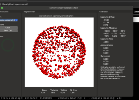
The compass module required calibration to provide accurate results. This was accomplished using MotionCal software, interfaced with an Arduino. After determining the hard and soft iron offsets, these values were applied in the code to perform software-based compass calibration. The compass heading relative to true north was then calculated based on the mounting direction. Proper register configuration was necessary to initialize the module and read the compass readings accurately.
Following are the compass register settings for proper initialization. They are derived as per the instructions described in the LSM303AGR datasheet.
void compass__init() {
  i2c__initialize(current_i2c, i2c_baudrate_hz, clock__get_peripheral_clock_hz(), &binary_semaphore_struct,
                  &mutex_struct);
  uint8_t ctrl_reg1_value = 0x8C;
  uint8_t ctrl_reg2_value = 0x02;
  uint8_t ctrl_reg3_value = 0x10;
  i2c__write_single(current_i2c, magnetometer_write, MAGNETOMETER_CTRL_REG1, ctrl_reg1_value);
  i2c__write_single(current_i2c, magnetometer_write, MAGNETOMETER_CTRL_REG2, ctrl_reg2_value);
  i2c__write_single(current_i2c, magnetometer_write, MAGNETOMETER_CTRL_REG3, ctrl_reg3_value);
}
Checkpoint Algorithm
The checkpoint algorithm finds the nearest checkpoint coordinate based on the current location among a series of checkpoints, considering also the distance to destination coordinates. Initially, it calculates the distance between the current location and the destination. Then, it iterates through each checkpoint, finding the distance from the current location to the checkpoint and from the checkpoint to the destination. If both distances are less than the minimum distance to the destination found so far, it updates the minimum distance and sets the next checkpoint accordingly. Finally, it returns the coordinates of the closest checkpoint considering the destination. This ensures proper navigation by selecting the most relevant checkpoint.
gps_coordinates_t find_closest_checkpoint_coordinate(gps_coordinates_t current_coordinate,
                                                     gps_coordinates_t destination_coordinate) {
  float min_distance_to_destination =
      coordinates__get_distance_to_destination(current_coordinate.latitude, current_coordinate.longitude,
                                               destination_coordinate.latitude, destination_coordinate.longitude);
  gps_coordinates_t next_checkpoint = destination_coordinate;

  for (uint8_t index = 0; index < max_checkpoints; index++) {
    float distance_to_waypoint =
        coordinates__get_distance_to_destination(current_coordinate.latitude, current_coordinate.longitude,
                                                 checkpoints[index].latitude, checkpoints[index].longitude);
    float distance_from_waypoint_to_destination =
        coordinates__get_distance_to_destination(checkpoints[index].latitude, checkpoints[index].longitude,
                                                 destination_coordinate.latitude, destination_coordinate.longitude);

    if (distance_to_waypoint < min_distance_to_destination &&
        distance_from_waypoint_to_destination < min_distance_to_destination) {
      min_distance_to_destination = distance_to_waypoint;
      next_checkpoint = checkpoints[index];
    }
  }
  return next_checkpoint;
}
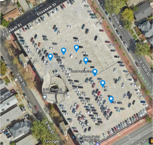
The following checkpoints were added to the checkpoint structure for the final demo, by manually verifying the coordinates using Google maps. The exact locations are difficult to derive, so coordinates away from the edges were chosen. Else these coordinates may appear to be beyond the building edges as per the GPS module on the RC car. The destination was set to the edge of the building and sent to the GEO module via CAN from the bridge controller.
Technical Challenges
As the geo logic came as the final step in the project, it could only be tested thoroughly after all other modules performed reliably. Several issues were identified and resolved on the geo controller side:
- Problem: The compass was giving unreliable values and not pointing to true north.
- Solution: The compass needed to be calibrated for the environment in which it was used, especially with the motor running.
- Problem: The compass was giving a fixed range of values 170-250 dgrees, instead of the full 0-359 range, despite repeated calibrations.
- Solution: The register configurations had to be updated. Specifically, the block data update needed to be set, and offset cancellation had to be enabled. This configuration was quite challenging as it took some time to arrive at the proper values that were needed for the registers to provide reliable readings. Initially, all the config registers were set to zero, which did output some values but were inaccurate and inconsistent. We decided to switch to more expensive compass that does self-calibration such as CMPW12 or CMPS14, but due to the delivery delays, we were not able to use it and decided to continue with LSM303AGR as its fix was identified.
- Problem: The GPS was giving no parsed outputs.
- Solution: The issue was traced back to soldering errors. The TX and RX wires were not swapped correctly; the TX of the board needed to connect to the RX of the GPS module, and vice versa.
- Problem: GPS was not acquiring stable lock inspite of testing it in open space and having the antenna connected.
- Solution: A button cell was added to the GPS module in the slot (rear side) provided in the module which enabled it to acquire locks faster.
- Problem: GPS parsing was incorrect and not returning proper data. Sometimes the buffer returned unknown symbols and empty strings.
- Solution: The line buffer size was increased to ensure all the received bytes were added to the buffer before the line removal function had to be called. In addition the RX and TX queue size was also incread in UART. It was also ensured that a lock was obtained before reading any data to update the coordinates.
Driver Node
Gitlab Link: https://gitlab.com/jincyjose491/sjtwo-c/-/tree/master/projects/driver?ref_type=heads
Hardware Design
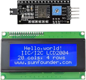
Driver node gives the interconnection between input and output. It receives input from geo node and sensor node and give commands to the motor node. The only hardware driver has is the LCD display and CAN transceiver. The LCD display used is a SunFounder IIC I2C TWI Serial 2004 20x4 LCD Module and is interfaced through an I2C bus through the I2C2 port. The module used and pin connections for LCD is shown below.
|
Software Design
Driver has more software and less hardware. For navigation, there are two algorithms - obstacle avoidance and GPS navigation. Obstacle avoidance has precedence over GPS navigation. In case of any obstacle, car avoids obstacle. In other cases, it follows the path from geo node input. When the destination is reached, car slows down and stops.
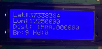
Different debug signals were added to check the logic when car was working. This helped in corrected undesired behavior of car taking turns without obstacle, stopping without reason, etc. The debug values used and their indications are shown in below table.
|
Obstacle Avoidance
The obstacle avoidance code is written in the form of a truth table that has 4 bit input and one bit output. Inputs are four sensor values and output the motor commands. Bases on changes in sensor values, the motor command also changes. The logic that worked for us is given below
|
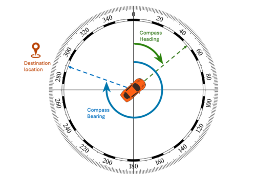
For GPS navigation the angle difference between heading and bearing is calculated and motor turn commands are generated based on this. Heading gives the current position in angle with respect to north. Bearing gives the angle to destination with respect to north. The logic that worked for our hardware is given below:
|
Technical Challenges
Since driver comes as the interconnect between all other nodes, the driver logic could be verified by outside testing only when we had stable input from geo and sensor node and motor nodes working as expected for given PWM. Unit testing can help in building of logic. But for actual test, we have to make sure all inputs are reliable. This can be verified with debug messages on bluetooth, CAN messages on busmaster, LCD display or LED indicators. The verification or debugging should be done in same frequency as which driver is processing.
- Problem: LCD was not displaying anything.
- Solution: Initially tried with 3.3V supply, then 5V supply and finally added level shifter to I2C pins. But the issue was slave address given in the datasheet was wrong. I got the correct slave address from web serial. After this was corrected, LCD worked well with 3.3V.
- Problem: LCD flickered a lot when everything was connected together.
- Solution: We initially connected all 5V supplies to a single 5V source. This included servo motor also. And it was causing the flicker. So, we powered up servo and rpm from ESC, all other sensors were powered separately from power bank and the issue was solved. This problem could have been avoided if more reports were read on how to power everything up.
- Problem: Driver gave a reverse signal for one clock cycle when there was no obstacle.
- Solution: Sensors gave random value for just one clock cycle and this caused driver to generate reverse command. After sensor inputs were corrected and made stable, the problem was solved.
- Problem: Driver not able to correct turning commands to motor even after sensing obstacle on side. This happened in the clock cycle when there was obstacle on all three side and it took reverse.
- Solution: We gave steps in angle changes in size of 5. Instead of direct 45 degree turn, car always turned in steps. So even though it sensed obstacle step sized turn angles took long clock cycles. So I finally reverted back to simple code logic of 45 degree turn and obstacle avoidance started working perfectly.
- Problem: We thought driver was giving wrong commands to sensor values that was there on app.
- Solution: Sensor values were updated at 1 Hz. Driver was working at 10Hz which is 10 times faster than what we see on app. So incorrect sensor value for just one cycle was not displayed. Finally debugged it in a hard way from all debugging sources listed above.
Communication Bridge Controller
The bridge controller aims to communicate with the Android application, receiving GPS coordinates to initiate vehicle movement and essential debug information for field testing. The user selects the final destination on Google Maps via the Android application, directing the car to navigate to the specified location.
Hardware Design
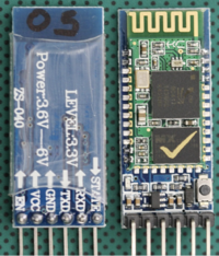
Bluetooth was the best fit solution providing range connectivity up to 10 meters. The right section of the Bluetooth Board has connection pins for power and signals as well as a 5V to 3.3V Regulator, LED, and level shifting. It has various features:
- External 8 Mbit flash memory
- Onboard voltage regulator
- No need for pull-up resistor during powering
- Programmable baud rate, Working mode
Bluetooth And SJTwo Board Connections
Software Design
Bridge controller Pseudo code:
1. Turning on Bridge controller.
2. Initialize Bluetooth with UART_3 settings.
3. Read Bluetooth message it received from the Android app.
- Parsing GPS data of the destination coordinates.
- Parsing START/STOP command from the app.
4. Send the received CAN message to the Android app over Bluetooth in 1Hz_periodic_callback.
Parsing GPS destination coordinates from App data string:
void bridge_controller__parse_gps_data(void) {

  printf("Buffer before == %s\n", gps_line);

  sscanf(gps_line, "%lf,%lf", &latitude_from_app, &longitude_from_app);

  if (latitude_from_app != 0 && longitude_from_app != 0) {

    dest_location.GPS_DEST_LATITUDE_SCALED = (int32_t)(latitude_from_app * 1000000);
    dest_location.GPS_DEST_LONGITUDE_SCALED = (int32_t)(longitude_from_app * 1000000);
    printf("Latitude is %ld and longitude is %ld \n", dest_location.GPS_DEST_LATITUDE_SCALED,
           dest_location.GPS_DEST_LONGITUDE_SCALED);

    for (int i = 0; i < sizeof(gps_line); i++) {
      gps_line[i] = '\0';
    }

    line_buffer__init(&line_buffer, gps_line, sizeof(gps_line));
  }
}
Parsing Start/Stop command from the App:
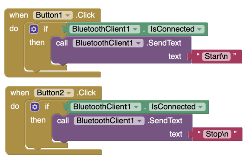
Once the App has provided a GPS destination coordinates data string, the car will stay in the idle state till either Start or stop command is given. The same approach of line buffer and sscanf API was used for the this function:
void sending_start_stop_from_app(void) {
  char read_line[50];

  sscanf(start_stop_line, "%s", start_stop);

  if (strcmp(start_stop_line, "Start") == 0) {
    app_commands.START_STOP_cmd = 1;
  } else if (strcmp(start_stop_line, "Stop") == 0) {
    printf("Reaceiving = %s\n", start_stop_line);
    app_commands.START_STOP_cmd = 0;
    printf("Command = %d\n", app_commands.START_STOP_cmd);
  } else {
    app_commands.START_STOP_cmd = 0;
  }
 }
}
Technical Challenges
- Problem: When sending destination data and start/stop command, it was behaving like one of them working at a time.
- Solution: We found that the size of line buffer was causing that issue, so if you are using line buffer make sure to keep line/line_buffer size according to your need.
Mobile Application
For this project, we have used MIT App inventor android development tool. is a high-level block-based visual programming language, originally built by Google and now maintained by the Massachusetts Institute of Technology. It allows newcomers to create computer applications for two operating systems: Android and iOS.
The web interface consists of a graphical user interface (GUI) very similar to Scratch and StarLogo, allowing users to drag-and-drop visual objects to create an application that can be tested on Android and iOS devices and compiled to run as an Android app. It uses a companion mobile app named MIT AI2 Companion providing live testing and debugging.
App Inventor provides integration with different online services, such as Google Sheets and Firebase.
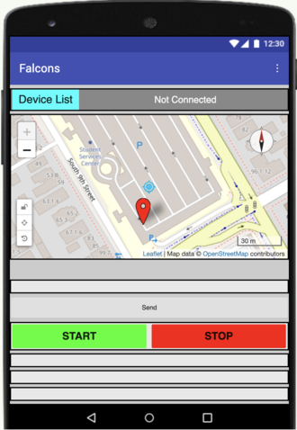
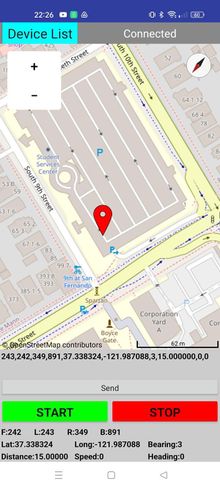
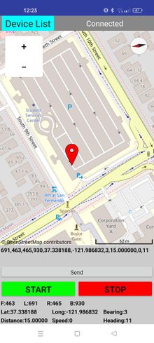
App Interface
Software Design
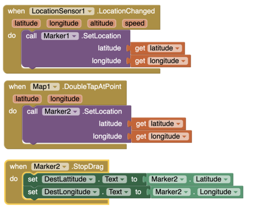
Map and Marker Blocks:
Start/Stop Blocks:
Technical Challenges
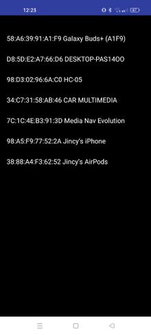
- Problem: Not able to find nearby devices even though the bluetooth was paired already.
- Solution: Every time after installing the MIT app on the device, make sure to allow all the permission from the device's app management.
Conclusion
The RC car project was a great opportunity to gain more embedded software and hardware skills. It also allowed us to showcase our technical proficiency and teamwork. The entire project was divided into 4 sections and specific task for each of the topics were curated during the initial weeks. The tasks were completed in a timely manner and the technical challenges were solved as a team, resulting in a successful demo where the RC car navigated itself to a defined destination avoiding all obstacles on its path. Along the journey, we learnt industry relevant skills such as unit test framewroks, test driven development, CAN communication and DBC files. The project also helped us get a firm understanding of the communication protocols and hardware development.
This project has been a tremedous educational journey. Though this journey had many ups and downs, the team collaboration and grit played a crucial role in ensuring the project was successful. The practical insights and hands-on learning we gained from this project far surpass any technical skills we might have acquired through theoretical learning.
Project Video
https://www.youtube.com/watch?v=W4M5YtxNGBo
Project Source Code
Advise for Future Students
- Make sure you have a clear idea on how to power up every modules in the project. This require careful distribution of power across the boards, sensors, motors. Connect everything together in the initial stage to see if entire module can work well when connected together. Doing this at an early stage helps to understand how to correctly power up everything. Again, you'll get an idea on which all modules should/should not be connected together, which module require additional power source, etc. from previous reports. Most of your problems could be solved from previous year reports. Don't limit yourself to 2-3 reports. Read more.. It'll be useful.
- Try to interface everything and see if communication is reliable between the nodes. Do this early so that you can work on project requirements.
- Find out your motor PWM for forward, neutral and reverse as soon as you get the car. You can save time here.
- Simplify the wire connections to save time when you meet. When we met in the initial few weeks, most of the time was spent on connecting everything from scratch and figuring out why something is not working.
- Get good quality hardware so that you don't have to invest more time here.
Acknowledgement
We would like to thank our instructor, Preet, for his effort, motivation, and guidance. We also appreciate the support from ISA volunteers Kyle and Ninaad. Preet's dedication has significantly contributed to our understanding of unit testing, C coding, software-hardware integration, teamwork, Git, and documentation.
We would also like to acknowledge all the teams who came before us, as their reports provided a lot of insights about the project.
References
1. Past RC Wiki Projects
2. Ultrasonic Range Finder Datasheet
3. ESC Calibration
4. ESC PWM information
5. ESC XL-5 PWM information
6. GEO Bearing information
7. GPS Module datasheet
8. Compass calibration

