Difference between revisions of "S22: Firebolt"
(→RPM Sensor) |
(→Team Members & Responsibilities) |
||
| (258 intermediate revisions by 3 users not shown) | |||
| Line 1: | Line 1: | ||
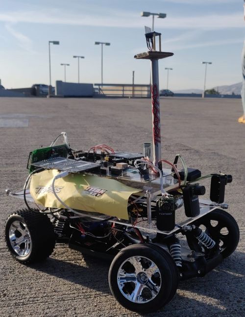
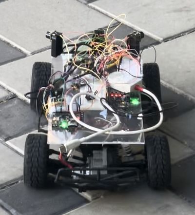
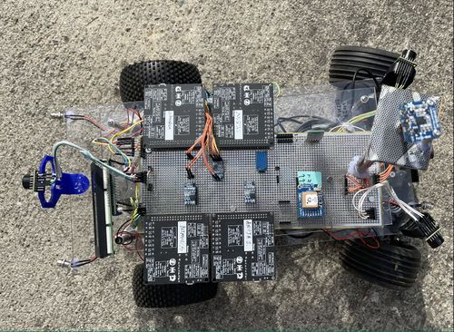
| − | [[File:Firebolt2.jpeg| | + | [[File:Firebolt2.jpeg|500px|thumb|right| The RC Car]] |
| − | |||
| − | |||
| − | |||
| − | |||
== Abstract == | == Abstract == | ||
| Line 23: | Line 19: | ||
* Choose good options for mounting the ultrasonic sensors on the car | * Choose good options for mounting the ultrasonic sensors on the car | ||
* Make a good GUI Android application for interfacing with the microcontroller | * Make a good GUI Android application for interfacing with the microcontroller | ||
| + | |||
| + | <div><ul> | ||
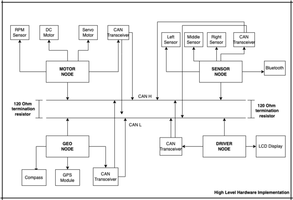
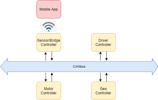
| + | <li style="display: inline-block;">[[File:High_Level_Implementation2.png|600px|thumb|Center|High Level Hardware]] </li> | ||
| + | </ul></div> | ||
==== Introduction ==== | ==== Introduction ==== | ||
| − | + | The controllers for the project are divided in 5 parts. Each controller has different tasks and communicate with each other over CAN bus. | |
# Driver Node | # Driver Node | ||
# GEO Node | # GEO Node | ||
| Line 39: | Line 39: | ||
<font color="black"> '''Priyanka Rai [https://www.linkedin.com/in/priyanka-rai-009ba975/ LinkedIn]'''''' | <font color="black"> '''Priyanka Rai [https://www.linkedin.com/in/priyanka-rai-009ba975/ LinkedIn]'''''' | ||
* Geo Controller | * Geo Controller | ||
| − | * GPS and Compass Interfacing | + | * GPS and Compass Interfacing |
| − | |||
* Integration Testing | * Integration Testing | ||
* Wiki Page Update | * Wiki Page Update | ||
| Line 46: | Line 45: | ||
<font color="black"> '''Ritu Patil [https://www.linkedin.com/in/ritu-patil/ LinkedIn]'''''' | <font color="black"> '''Ritu Patil [https://www.linkedin.com/in/ritu-patil/ LinkedIn]'''''' | ||
* Motor Controller | * Motor Controller | ||
| + | * RPM Sensor | ||
* Integration Testing | * Integration Testing | ||
* Wiki Page Update | * Wiki Page Update | ||
| Line 52: | Line 52: | ||
* Driver Node | * Driver Node | ||
* LCD interfacing | * LCD interfacing | ||
| − | |||
* Integration Testing | * Integration Testing | ||
* Wiki Page Update | * Wiki Page Update | ||
| Line 60: | Line 59: | ||
* Integration Testing | * Integration Testing | ||
* Wiki Page Update | * Wiki Page Update | ||
| + | * Bluetooth integration with Sensor | ||
<font color="black"> '''Dhanush Babu [https://www.linkedin.com/in/dhanushsbabu/ LinkedIn]'''''' | <font color="black"> '''Dhanush Babu [https://www.linkedin.com/in/dhanushsbabu/ LinkedIn]'''''' | ||
| Line 524: | Line 524: | ||
* Finally we decided to use the prototype board for mounting all the components and stabilizing our hardware. | * Finally we decided to use the prototype board for mounting all the components and stabilizing our hardware. | ||
<div><ul> | <div><ul> | ||
| − | <li style="display: inline-block;">[[File: | + | <li style="display: inline-block;">[[File:Final_Hardware_Physical.jpeg|500px|thumb|Left|Protoype_Board]]</li> |
</ul></div> | </ul></div> | ||
| Line 558: | Line 558: | ||
|- | |- | ||
|- | |- | ||
| − | ! colspan="4"| Driver | + | ! colspan="4"| Driver Heartbeat |
|- | |- | ||
|- | |- | ||
|1 | |1 | ||
| − | |||
| − | |||
| − | |||
| − | |||
| − | |||
|100 | |100 | ||
|Driver Heartbeat | |Driver Heartbeat | ||
|Motor, Sensor, Geo | |Motor, Sensor, Geo | ||
|- | |- | ||
| − | ! colspan="4"| Sensor | + | ! colspan="4"| Start Stop signal from Android app to Driver |
| + | |- | ||
| + | |- | ||
| + | |1 | ||
| + | |101 | ||
| + | |Bridge Sensor | ||
| + | |Driver | ||
|- | |- | ||
| + | ! colspan="4"| Ultrasonic sensors data transmit | ||
|- | |- | ||
| − | | | + | |- |
| + | |2 | ||
|200 | |200 | ||
|Sensor sonars from front, back, left ,right sensor | |Sensor sonars from front, back, left ,right sensor | ||
|Driver | |Driver | ||
|- | |- | ||
| + | ! colspan="4"| Destination Location | ||
|- | |- | ||
| − | ! colspan="4"| Motor | + | |- |
| + | |4 | ||
| + | |250 | ||
| + | |Bridge Sensor | ||
| + | |Geo | ||
| + | |- | ||
| + | |- | ||
| + | ! colspan="4"| Driver to Motor Command | ||
|- | |- | ||
|- | |- | ||
| − | | | + | |5 |
| − | | | + | |300 |
| − | |motor | + | |Speed and steering direction for the motor |
| − | | | + | |Motor |
|- | |- | ||
|- | |- | ||
| Line 592: | Line 603: | ||
|- | |- | ||
|- | |- | ||
| − | | | + | |6 |
|400 | |400 | ||
|Bearing, Heading and Distance | |Bearing, Heading and Distance | ||
| + | |Driver | ||
| + | |- | ||
| + | |- | ||
| + | ! colspan="4"| Motor Controller | ||
| + | |- | ||
| + | |- | ||
| + | |7 | ||
| + | |600 | ||
| + | |Motor speed | ||
|Driver | |Driver | ||
|- | |- | ||
| Line 601: | Line 621: | ||
|- | |- | ||
|- | |- | ||
| − | | | + | |8 |
|700 | |700 | ||
|Driver Debug | |Driver Debug | ||
| Line 607: | Line 627: | ||
|- | |- | ||
|- | |- | ||
| − | | | + | |9 |
|750 | |750 | ||
|Geo Debug | |Geo Debug | ||
| Line 667: | Line 687: | ||
BO_ 300 DRIVER_TO_MOTOR: 2 DRIVER | BO_ 300 DRIVER_TO_MOTOR: 2 DRIVER | ||
| − | SG_ DRIVER_TO_MOTOR_speed : 0|8@1+ ( | + | SG_ DRIVER_TO_MOTOR_speed : 0|8@1+ (1,0) [-30|30] "kmph" MOTOR |
| − | SG_ DRIVER_TO_MOTOR_direction : 8|8@1 | + | SG_ DRIVER_TO_MOTOR_direction : 8|8@1- (1,-2) [-2|2] "degrees" MOTOR |
BO_ 400 GEO_CONTROLLER_COMPASS: 8 GEO | BO_ 400 GEO_CONTROLLER_COMPASS: 8 GEO | ||
| Line 695: | Line 715: | ||
CM_ SG_ 100 DRIVER_HEARTBEAT_cmd "Heartbeat command from the driver"; | CM_ SG_ 100 DRIVER_HEARTBEAT_cmd "Heartbeat command from the driver"; | ||
| + | VAL_ 300 DRIVER_TO_MOTOR_direction -2 "MOTOR_direction_HARD_LEFT" -1 "MOTOR_direction_SOFT_LEFT" 0 "MOTOR_direction_STRAIGHT" 1 "MOTOR_direction_SOFT_RIGHT" 2 "MOTOR_direction_HARD_RIGHT" ; | ||
VAL_ 700 car_steering_status 2 "RIGHT" 1 "LEFT" 0 "STRAIGHT"; | VAL_ 700 car_steering_status 2 "RIGHT" 1 "LEFT" 0 "STRAIGHT"; | ||
VAL_ 700 car_driving_status 2 "BACKWARD" 1 "FORWARD" 0 "STOPPED"; | VAL_ 700 car_driving_status 2 "BACKWARD" 1 "FORWARD" 0 "STOPPED"; | ||
</pre> | </pre> | ||
| + | |||
| + | === Technical Challenges === | ||
| + | * The CAN transceivers that we bought had inbuilt 120 ohm resistor each, which we didn't notice. And every time we interfaced all the four nodes the data won't show up in the busmaster software. We found this very late and until then we thought it's hardware/dbc file issue and wasted potential amount of time in debugging.So we de-soldered those termination resistors and we were able to see our data smoothly on busmaster. | ||
| + | * As an advice, make sure at the end of all four nodes after adding termination resistors of 120 ohm on both sides, the resultant resistance is 60 ohms. Only then all four nodes can communicate over CAN bus. | ||
== Sensor and Bluetooth ECU == | == Sensor and Bluetooth ECU == | ||
| + | === Hardware Design === | ||
| + | |||
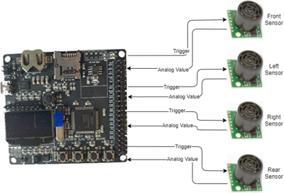
| + | The obstacle detection sensors used here are Ultrasonic sensors. The HRLV-MaxSonar-EZ1 sensors from MaxBotix are used here. In these sensors there is membrane which needs to be triggered in order to generate and send ultrasonic waves every few seconds. When ultrasonic waves collide and come back and strikes with this membrane a pulse is generated which is used for sensing. | ||
| + | |||
| + | |||
| + | [[File:Sensor_Node.png|left|400px|thumb|Sensor Controller Diagram]] | ||
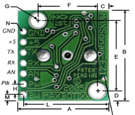
| + | [[File:Ultrasonic99.png|center|400px|thumb|Sensor Pins]] | ||
| − | |||
| − | |||
| − | + | ||
| + | {| class="wikitable" width="auto" style="text-align: center; margin-left: auto; margin-right: auto; border: none;" | ||
| + | |+Pin connections between board and sensor: | ||
| + | |- | ||
| + | ! scope="col"| Sl No. | ||
| + | ! scope="col"| SJ2 board Pin No. | ||
| + | ! scope="col"| Ultrasonic sensor Pin No. | ||
| + | ! scope="col"| Function | ||
| + | |- | ||
| + | ! scope="row"| 1. | ||
| + | | ADC Pin 1.30 | ||
| + | | AN(Front left sensor) | ||
| + | | Input to ADC channel 4 | ||
| + | |- | ||
| + | ! scope="row"| 2. | ||
| + | | ADC Pin 1.31 | ||
| + | | AN(Front right sensor) | ||
| + | | Input to ADC channel 5 | ||
| + | |- | ||
| + | ! scope="row"| 3. | ||
| + | | ADC Pin 1.26 | ||
| + | | AN(Front sensor) | ||
| + | | Input to ADC channel 3 | ||
| + | |- | ||
| + | ! scope="row"| 4. | ||
| + | | ADC Pin 1.25 | ||
| + | | AN(Rear sensor) | ||
| + | | Input to ADC channel 3 | ||
| + | |- | ||
| + | ! scope="row"| 5. | ||
| + | | GPIO Pin 0.6 | ||
| + | | Rx(Front left sensor) | ||
| + | | Triggering pulse for left sensor | ||
| + | |- | ||
| + | ! scope="row"| 6. | ||
| + | | GPIO Pin 0.8 | ||
| + | | Rx(Front right sensor) | ||
| + | | Triggering pulse for right sensor | ||
| + | |- | ||
| + | ! scope="row"| 7. | ||
| + | | GPIO Pin 0.9 | ||
| + | | Rx(Front sensor) | ||
| + | | Triggering pulse for front sensor | ||
| + | |- | ||
| + | ! scope="row"| 8. | ||
| + | | GPIO Pin 0.7 | ||
| + | | Rx(Rear sensor) | ||
| + | | Triggering pulse for rear sensor | ||
| + | |- | ||
| + | |} | ||
| + | |||
| + | |||
| + | Apart from the pin connections for the Sensor node the important thing is to mount the sensors at particular angles. The angle placement is critical for left and right sensor as we faced lot of problems while detecting the walls. We chose the angle by error and trial method by simply placing the sensors at different angles. We tried keeping the angle above the 45 degrees so that to provide wider angle for the obstacles to detect. | ||
=== Software Design === | === Software Design === | ||
| Line 712: | Line 794: | ||
The sensor node has to receive values from all the sensors and send the distance values on the CAN bus for the driver to run the obstacle avoidance logic. | The sensor node has to receive values from all the sensors and send the distance values on the CAN bus for the driver to run the obstacle avoidance logic. | ||
| − | + | ====== Receive sensor values ====== | |
Four sensors are used here. Three in the front and one at the rear side. We need four ADC channels to address the receiving from all sensors. In order to use four pins on the SJ2 board we need to set the pins to analog mode. In the adc.h file and adc.c file there are only three channels initialized, so one needs to add ADC channel 3 in these files. On how to use these sensors, the datasheet of helped a lot. It addresses every aspect of how to use this particular sensor and the solution to most of the problem that can arise. All the sensor raw values are digitally converted in the range of 0 to 1024( 10 bit ADC). These value is in inches as mentioned in the datasheet. So, one needs to convert it into centimeter by applying some formula. The formula can be different based on the configuration used to setup the ADC channel even if same sensor is used. | Four sensors are used here. Three in the front and one at the rear side. We need four ADC channels to address the receiving from all sensors. In order to use four pins on the SJ2 board we need to set the pins to analog mode. In the adc.h file and adc.c file there are only three channels initialized, so one needs to add ADC channel 3 in these files. On how to use these sensors, the datasheet of helped a lot. It addresses every aspect of how to use this particular sensor and the solution to most of the problem that can arise. All the sensor raw values are digitally converted in the range of 0 to 1024( 10 bit ADC). These value is in inches as mentioned in the datasheet. So, one needs to convert it into centimeter by applying some formula. The formula can be different based on the configuration used to setup the ADC channel even if same sensor is used. | ||
| + | |||
| + | ====== Sending sensor values in terms of distance to CAN ====== | ||
| + | |||
| + | The raw values coming from the sensor needs to be filtered before sending on the CAN bus. The more information about filtering is mentioned in the techical challenges section. The below diagram shows the detailed flowchart of software design implemented for the sensor node. | ||
| + | |||
| + | |||
| + | [[File:f8.png|center|6600px|thumb|Sensor Controller Diagram]] | ||
=== Technical Challenges === | === Technical Challenges === | ||
| − | The main challenge while using ultrasonic sensor with this particular project is of crosstalk. While detecting objects in the front all the front sensors waves are interfering with each other giving false values in the left or right sensor while the object is in the front only. The datasheet addresses this issues and what to do when multiple sensors are used in a system. It says that trigger each sensor are different time period in order to avoid crosstalk. So we triggered the front and rear at one particular time and left and right at one particular time. One sequence is triggered at | + | *The main challenge while using ultrasonic sensor with this particular project is of crosstalk. While detecting objects in the front all the front sensors waves are interfering with each other giving false values in the left or right sensor while the object is in the front only. The datasheet addresses this issues and what to do when multiple sensors are used in a system. It says that trigger each sensor are different time period in order to avoid crosstalk. So we triggered the front and rear at one particular time and left and right at one particular time. One sequence is triggered at particular 10Hz and other sequence is triggered at another 10Hz. There is a division of callbacks counts in 100Hz and a lock mechanism is used in order to used different 20Hz period out of 100Hz. |
| − | |||
| − | |||
| + | *For frequency noise measurements like when the values suddenly change or vary between certain range sometimes, a filter is implemented. The most common filter for this type of use is median filter where a series of values are stored in a array and median is taken of all the values stored in that array. | ||
| Line 736: | Line 824: | ||
The DC motor is controlled by ESC using PWM signals provided by the motor controller for forward and reverse movements. We used the 9v NiMH battery to power up the ESC. The DC motor is powered by the ESC which has a dc-to-dc converter which converts 9v to 6v. The output from the ESC is used to power the Servo motor. ESC has an ease set button which is used for calibration and setting different modes for the car. | The DC motor is controlled by ESC using PWM signals provided by the motor controller for forward and reverse movements. We used the 9v NiMH battery to power up the ESC. The DC motor is powered by the ESC which has a dc-to-dc converter which converts 9v to 6v. The output from the ESC is used to power the Servo motor. ESC has an ease set button which is used for calibration and setting different modes for the car. | ||
| − | The car can be operated in the following 3 modes: | + | '''The car can be operated in the following 3 modes:''' |
<br/> | <br/> | ||
Sport mode(100% Forward, 100% Brakes, 100% Reverse) | Sport mode(100% Forward, 100% Brakes, 100% Reverse) | ||
| Line 752: | Line 840: | ||
PWM 15.1 to 20 for the forward. | PWM 15.1 to 20 for the forward. | ||
| − | {| class="wikitable" | + | {| class="wikitable" width="auto" style="text-align: center; margin-left: auto; margin-right: auto; border: none;" |
| + | |+ESC Pinout | ||
|- | |- | ||
! scope="col"| Wires on ESC | ! scope="col"| Wires on ESC | ||
| Line 792: | Line 881: | ||
PWM 15.1 to 20 for turning right. | PWM 15.1 to 20 for turning right. | ||
| − | {| class="wikitable" | + | {| class="wikitable" width="auto" style="text-align: center; margin-left: auto; margin-right: auto; border: none;" |
| + | |+Servo Pinout | ||
|- | |- | ||
! scope="col"| Wires on ESC | ! scope="col"| Wires on ESC | ||
| Line 816: | Line 906: | ||
==== RPM Sensor ==== | ==== RPM Sensor ==== | ||
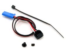
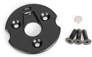
| − | The RPM sensor is used as an input to maintain a constant speed of the vehicle. | + | The RPM sensor is used as an input to maintain a constant speed of the vehicle. The sensor we are using is Traxxas RPM sensor which using hall effect to detect the movement of the DC motor. |
| + | <br/> | ||
| + | '''Mounting the sensor:''' | ||
<br/> | <br/> | ||
| − | + | There are two parts to the RPM sensor - one is the trigger magnet and the other is the sensor. The sensor mounts on the inside of the gear cover, the trigger magnet mounts on the DC motor shaft. The gear cover and motor shaft need to be removed using the toolkit provided along with the RC car. The mounting process can be found on youtube. | |
<br/> | <br/> | ||
| − | + | '''How the sensor works:''' | |
| + | <br/> | ||
| + | The trigger magnet attaches to the spur gear. The sensor uses the DC voltage of the motor to trigger a pulse on the sensor for every rotation of the spur gear. These pulses are sent as hardware interrupt to the SJ2 board. The number of pulses are counted for every half second and that is converted into RPM and KMPH. The RPM sensor has 3 wires, the white wire is the output wire that provides the pulses to the SJ2 Board, and the other wires are Supply(3.3V) and GND. | ||
| − | {| class="wikitable" | + | {| class="wikitable" width="auto" style="text-align: center; margin-left: auto; margin-right: auto; border: none;" |
| + | |+RPM Pinout | ||
|- | |- | ||
! scope="col"| Wires on ESC | ! scope="col"| Wires on ESC | ||
| Line 832: | Line 927: | ||
| WHITE | | WHITE | ||
|- | |- | ||
| − | ! scope="row"| VDD( | + | ! scope="row"| VDD(3.3V) |
| Power Input | | Power Input | ||
| RED | | RED | ||
| Line 853: | Line 948: | ||
At startup the motor is initialized by giving a neutral PWM signal for 3s and the interrupt for the rpm sensor input is setup as well. | At startup the motor is initialized by giving a neutral PWM signal for 3s and the interrupt for the rpm sensor input is setup as well. | ||
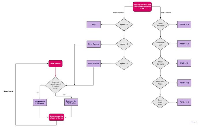
| − | The motor receives angle for steering and speed in a single | + | The motor receives angle for steering and speed in a single CAN message from the driver ECU. After receiving the command the speed value is converted into corresponding value of PWM by increasing or decreasing neutral PWM value in steps of 0.01. The physical value of the motor speed is compared to the speed received from the driver and it is reduced or increased to match with the desired speed. For reverse a PWM of 14.5 is given to smoothly reverse the car. |
| − | The direction of the car is set according to the value of ENUM received from the driver ECU. For navigation the car takes soft turns and when and obstacle is detected it takes hard turns to avoid collisions. | + | The direction of the car is set according to the value of ENUM received from the driver ECU. For navigation the car takes soft turns and when and obstacle is detected it takes hard turns to avoid collisions. |
| + | |||
| + | '''The period_callbacks__initialize() function calls the following functions:''' | ||
| + | * can_bus_initializer: Initializes CAN buffers and sets baud rate | ||
| + | * initialize_speed_sensor_interrupts: sets up GPIO pin as hardware interrupt | ||
| + | * motor_init_pwm: initializes pwm pin. | ||
| + | |||
| + | '''The period_callbacks__1Hz() function calls the following function:''' | ||
| + | * can_handler__handle_all_incoming_messages_1hz: handles the incoming messages based on mesg ID. | ||
| + | * can_handler__transmit_messages_1hz: sends the motor speed to Driver controller. | ||
| + | |||
| + | '''The period_callbacks__10Hz() function calls the following functions:''' | ||
| + | * pwm1__set_duty_cycle: to calibrate the ESC by sending neutral signal for few seconds. | ||
| + | * clear_rotations: clears interrupt counter every 0.5 seconds | ||
| + | * can_handler__handle_all_incoming_messages: receives any message frame sent on the CAN bus. | ||
| + | |||
<br/> | <br/> | ||
| Line 864: | Line 974: | ||
* ESC calibration: The ESC controlling the DC motor goes out of calibration again and again. We had to connect it to the receiver of the RC car and re-calibrate it again. Finally I added a neutral signal in for the first 3 seconds in the initialization sequence of the motor so that the ESC can be calibrated every time the controller is reset or powered on. | * ESC calibration: The ESC controlling the DC motor goes out of calibration again and again. We had to connect it to the receiver of the RC car and re-calibrate it again. Finally I added a neutral signal in for the first 3 seconds in the initialization sequence of the motor so that the ESC can be calibrated every time the controller is reset or powered on. | ||
* Changing PWM: PWM value of the motor will change sometimes and depends on the weight of the car and also a faster speed might not give enough time for the sensor to detect an obstacle. Hence keeping a slow and steady speed and relying on the RPM sensor is necessary to ensure the car keeps moving and doesn't stop on any inclines. | * Changing PWM: PWM value of the motor will change sometimes and depends on the weight of the car and also a faster speed might not give enough time for the sensor to detect an obstacle. Hence keeping a slow and steady speed and relying on the RPM sensor is necessary to ensure the car keeps moving and doesn't stop on any inclines. | ||
| − | * Receiving steer commands at higher frequency helped in reducing the response time in obstacle avoidance. | + | * Receiving steer commands at a higher frequency helped in reducing the response time in obstacle avoidance compared to previously when it was being received at 10Hz. |
| + | <br/> | ||
<HR> | <HR> | ||
<BR/> | <BR/> | ||
| Line 872: | Line 983: | ||
=== Hardware Design === | === Hardware Design === | ||
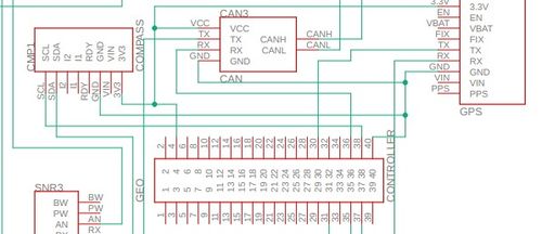
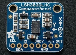
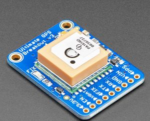
| + | The Geographical controller does the processing for compass data and GPS data. After processing the data for heading ,bearing and distance to destination , the controller sends these data over can bus to the Driver node. The GPS module is interfaced with SJ2 board using UART. SJ2 board gets the data (NMEA string) for GPS coordinates processing. The controller sends the command to GPS module to filter the string and only send GPGGA string. The Compass module is interfaced over I2C to find the heading for car navigation. The CAN transceiver uses port 0 (can1) of the SJ2 board. | ||
| + | |||
| + | <li style="display: inline-block;"> [[File:Geo_Node_Schematic.jpg|500px|thumb|centre|]] </li> | ||
| + | <li style="display: inline-block;">[[File:compass_Firebolt.jpg|300px|thumb|center|3 Axis Magnetometer (eCompass)]] </li> | ||
| + | <li style="display: inline-block;"> [[File:GPS_Firebolt.jpg|300px|thumb|centre|GPS Module]] </li> | ||
| − | + | {| class="wikitable" width="auto" style="text-align: center; margin-left: auto; margin-right: auto; border: none;" | |
| − | + | |+Geographical Node Pinout | |
| − | + | |- | |
| + | ! scope="col"| SJTwo Board | ||
| + | ! scope="col"| GPS/Compass Module | ||
| + | ! scope="col"| Description | ||
| + | |- | ||
| + | | P0.15 (TX3) | ||
| + | | RX | ||
| + | | Adafruit GPS Breakout | ||
| + | |- | ||
| + | | P0.16 (RX3) | ||
| + | | TX | ||
| + | | Adafruit GPS Breakout | ||
| + | |- | ||
| + | | P0.10 (SDA) | ||
| + | | SDA | ||
| + | | Adafruit Magnetometer | ||
| + | |- | ||
| + | | P0.11 (SCL) | ||
| + | | SCL | ||
| + | | Adafruit Magnetometer | ||
| + | |- | ||
| + | | P0.1 | ||
| + | | CAN transceiver (Tx) | ||
| + | | CAN transmit | ||
| + | |- | ||
| + | | P0.0 | ||
| + | | CAN transceiver (Rx) | ||
| + | | CAN receive | ||
| + | |- | ||
| + | | Vcc 3.3V | ||
| + | | Vcc | ||
| + | | Vcc | ||
| + | |- | ||
| + | | GND | ||
| + | | GND | ||
| + | | Ground | ||
| + | |- | ||
| + | |} | ||
| + | |||
<BR/> | <BR/> | ||
=== Software Design === | === Software Design === | ||
The GEO controller consisted of 4 main parts which are: | The GEO controller consisted of 4 main parts which are: | ||
| − | |||
| − | |||
| − | |||
| − | |||
| − | The Geo | + | *1. GPS |
| + | *2. Compass | ||
| + | *3. Waypoints | ||
| + | *4. Geo Logic | ||
| + | |||
| + | ====Overview==== | ||
| + | |||
| + | These code modules, calculate compass heading degree, bearing, parse GPS coordinates, calculate the checkpoints the RC car has to go through when navigating to a destination, send distance to destination to driver node, and handle messages received on the CAN bus. | ||
| + | |||
| + | '''The period_callbacks__initialize() function calls the following functions:''' | ||
| + | |||
| + | *can_bus_initializer__init(): initializes the CAN bus to handle MIA and messages(CAN). | ||
| + | *gps__init(): initializes the GPS interface(UART). | ||
| + | *geo_compass__setup_magnetometer(): initializes the compass interface(I2C). | ||
| + | |||
| + | '''The period_callbacks__1Hz() function calls the following function:''' | ||
| + | |||
| + | * can_handler__handle_all_incoming_messages_1hz(): handles the incoming messages based on mesg ID. | ||
| + | * gps__setup_command_registers(): sends command to GPS module to receive only GPGGA string. | ||
| + | * can_handler__transmit_messages_10hz(): sends the heading ,bearing and distance to Driver controller. | ||
| + | |||
| + | '''The period_callbacks__10Hz() function calls the following functions:''' | ||
| + | |||
| + | *gps_run_once(): parses the NMEA string to get current coordinates | ||
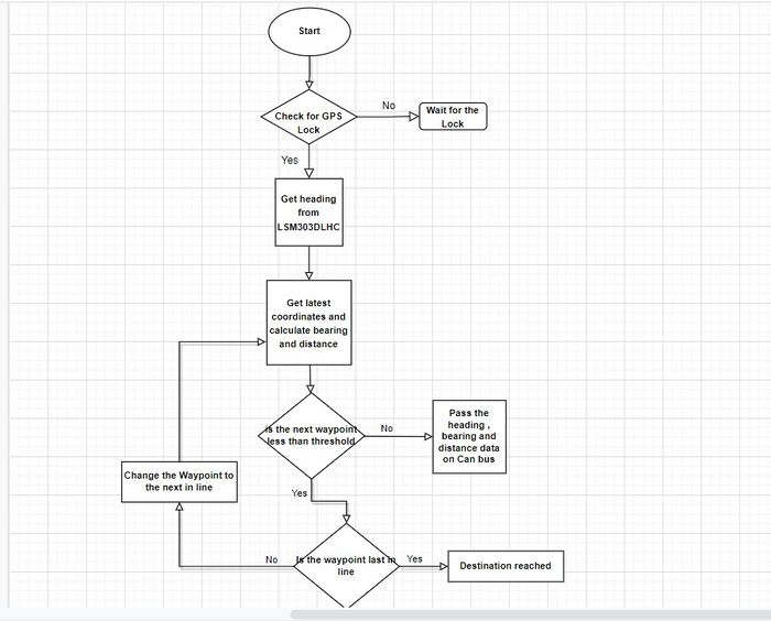
| + | [[File:FlowChart_Geo_Logic.jpg|center|700px|thumb|Geo Logic Flowchart]] | ||
| + | |||
| + | ====GPS==== | ||
| + | *In the initialization process of the GPS, the line buffer module is configured to parse the GPS messages, the GPIOs P0.15(Tx) and P0.16(Rx) are configured, UART interrupt queues enabled, and the UART is configured at a baudrate of 9600(GPS standard). | ||
| + | |||
| + | *Configuration | ||
| + | In the gps__run_once_10Hz() the GPS is initially configured once to disable all NMEA messages except GPGGA which is message chosen to parse the coordinates and GPS lock. | ||
| + | |||
| + | *Parsing NMEA GPGGA messages | ||
| + | The GPS module constantly transmits NMEA GPGGA messages over UART to the SJ2 MCU. These messages which come in the form of a string are stored character by character in the line | ||
| + | buffer until a new line character which indicates the end of string. The stored string is then extracted from the line buffer. The extracted line is then tokenized to parse the | ||
| + | latitude, latitude direction, longitude, longitude direction, and fix quality. South and West directions are also properly handled to make the latitude and longitude negative | ||
| + | values. | ||
| + | |||
| + | *GPS lock | ||
| + | Although the GPS module has fix indication , but GPGGA string has field for FIX status also. Getting the Fix/Lock status using the string is much easier than using GPIO pins to get | ||
| + | the Lock status using FIX led of the GPS module. The Lock status/flag was used as a condition to calculate the bearing and checkpoints only when the GPS had a lock meaning that the | ||
| + | current coordinates were valid. | ||
| + | |||
| + | ====Compass==== | ||
| + | |||
| + | *Initialization | ||
| + | The compass initialization configures the LSM303DLHC magnetometer and accelerometer registers over I2C bus to default settings using default gain and single mode. | ||
| + | |||
| + | *Heading degree computation | ||
| + | The compass heading degree is computed by using the tilt compensation algorithm and the pitch and roll values of LSM303DLHC accelerometer. The tilt compensation algorithm ensures | ||
| + | that the values of the compass heading are precise. The formulae used to calibrate the compass are mentioned below: | ||
| + | |||
| + | *Pitch and Roll:<br/> | ||
| + | |||
| + | pitch = asin(-acc_x / sqrt(acc_y * acc_y + acc_z * acc_z + acc_x * acc_x)) <br/> | ||
| + | roll = asin((acc_y / sqrt(acc_y * acc_y + acc_z * acc_z + acc_x * acc_x)) / cos(pitch)) | ||
| + | |||
| + | |||
| + | *Tilt compensated magnetic sensor values:<br/> | ||
| + | |||
| + | mag_x = mag_x * cos(pitch) + mag_z * sin(pitch) | ||
| + | mag_y = mag_y * cos(roll) + mag_x * sin(roll) * sin(pitch) - mag_z * sin(roll) * cos(pitch) | ||
| + | mag_z = -mag_x * cos(roll) * sin(pitch) + mag_y * sin(roll) + mag_z * cos(roll) * cos(pitch) | ||
| + | |||
| + | |||
| + | Luckily our module had no offset but it might need to be compensated for the offset if there is any. | ||
| + | |||
| + | *Heading angle | ||
| + | |||
| + | heading = atan2(mag_y, mag_x) * r2d | ||
| + | r2d is radian to degree conversion function | ||
| + | |||
| + | This heading is calculated in radians since atan2 returns a value between -π and +π. Therefore, before converting the heading into degrees the value needs to be normalized to put | ||
| + | it in the range from 0 to 360 degrees. | ||
| + | |||
| + | ====Checkpoints==== | ||
| + | |||
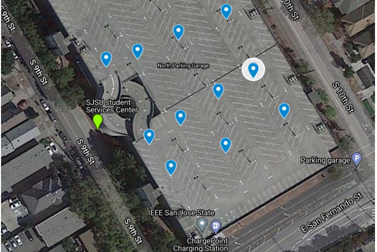
| + | In real world, the source and destination are not on a straight line. The car has to find the best possible and smallest route to its final destination. In this project keeping that in mind we have used checkpoint algorithm. These waypoints are known coordinates which are given according to the destination and source path. The car needs to follow the route determined by the waypoints from source to destination. | ||
| + | |||
| + | We choose 10 points over a known location and hardcoded these coordinates in GEO node logic. Once our car gets the destination coordinates from Bridge and Sensor controller, it starts giving Heading , Bearing and Distance values to Driver Node. This waypoint must satisfy the below conditions: | ||
| + | * It is the closest waypoint to the current location of the car. | ||
| + | * Waypoint to destination distance is less than the current coordinate to the final coordinate distance. | ||
| + | [[File:Checkpoint.jpg]] | ||
| + | |||
| + | So when the algorithm finds the destination coordinates, then bearing is calculated with that particular coordinate, so that car can be further instructions to move towards that particular point. As shown in the figure below, our algorithm keeps finding new coordinates with time (orange ones) and at last go to the final destination coordinates. The algorithm is mentioned below in the form of flowchart and code: | ||
| + | |||
| + | The way point calculation determines the nearest way point continuously by computing the distance using Haversine formula and current location using GPS. | ||
| + | The heading and bearing is also computed using the Haversine formula and is sent over the CAN bus for heading correction.* | ||
| + | Alternatively, once the car is within the threshold distance, next way point is selected and the car heads to the next way point. | ||
| + | |||
| + | To calculate the geographical distance between the two points the haversine formula was used which is called periodically from the waypoints.c module. Below is the formula used: | ||
| + | |||
| + | a = sin²(ΔlatDifference/2) + cos(lat1) * cos(lt2) * sin²(ΔlonDifference/2) | ||
| + | c = 2 * atan2(sqrt(a), sqrt(1−a)) | ||
| + | d = R * c | ||
| + | |||
| + | *where: | ||
| + | **ΔlatDifference = latitude 2 - latitude 1 (difference of latitude) | ||
| + | **ΔlonDifference = longitude 2 - longitude 1 (difference of longitude) | ||
| + | **R = 6371000.0 meters = radius of earth | ||
| + | **d = distance computed between two points | ||
| + | **a and c are intermediate steps | ||
| + | |||
| + | |||
| + | *Bearing Angle computation | ||
| − | + | The bearing which is the angle towards our desired destination is computed using the formulas below referenced at this [https://www.igismap.com/formula-to-find-bearing-or-heading-angle-between-two-points-latitude-longitude/ link]. | |
| − | + | X = cos θb * sin ∆L | |
| + | Y = cos θa * sin θb – sin θa * cos θb * cos ∆L | ||
| − | + | β = atan2(X,Y) | |
| + | |||
| + | *where: | ||
| + | **θa = current latitude | ||
| + | **θb = destination latitude | ||
| + | **∆L = destination longitude - current longitude | ||
| + | **β = heading degree in radians | ||
| + | |||
| + | The bearing is also calculated in radians since atan2 returns a value between -π and +π. Therefore, before converting the heading into degrees the value needs to be normalized to put it in the range from 0 to 360 degrees. The calculated bearing is then sent to the driver node which use the compass heading degree and the bearing to align the car toward the target destination. | ||
=== Technical Challenges === | === Technical Challenges === | ||
<HR> | <HR> | ||
| + | * Adafruit GPS | ||
| + | ** Problem: The data from the GPS was being refreshed every second which was causing issues for the controller. | ||
| + | *** Solution: Send the command to the GPS module only send the SJ2 board GPGGA data. | ||
| + | ** Problem: It would take way too long for the GPS to have a fix causing a 3-5 minute way when indoors and over 45 seconds when outside | ||
| + | *** Solution: Utilize the external antenna. It was able to get a fix inside in under a minute while outside within 25 seconds. Using separate battery can reduce the fix time. | ||
| + | |||
| + | * Compass | ||
| + | ** Problem: Standalone testing of the controller gave correct data but when integrated with all modules the data was inaccurate (not 0 to 360 degrees). | ||
| + | *** Solution: When mounting the compass module on RC car, mount it away from Motor controller and mount it on some height to avoid any interference with other nodes. | ||
| + | |||
| + | *General | ||
| + | ** Problem: The Geo node needs extensive testing with other nodes, if not unit tested and integration tested, it is not going to work properly. | ||
== Driver Node == | == Driver Node == | ||
| Line 908: | Line 1,183: | ||
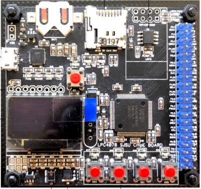
<li style="display: inline-block;">[[File:SJTWO.jpg|400px|thumb|Left|Sjtwo-board]] </li> | <li style="display: inline-block;">[[File:SJTWO.jpg|400px|thumb|Left|Sjtwo-board]] </li> | ||
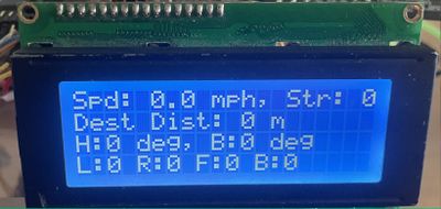
<li style="display: inline-block;">[[File:LCD_DIS.jpg|400px|thumb|Right|LCD Display]] </li> | <li style="display: inline-block;">[[File:LCD_DIS.jpg|400px|thumb|Right|LCD Display]] </li> | ||
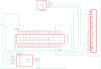
| + | <li style="display: inline-block;">[[File:Final_Sch2.png|400px|thumb|Right|Pinouts]] </li> | ||
=== Software Architecture Driver Logic=== | === Software Architecture Driver Logic=== | ||
| Line 957: | Line 1,233: | ||
<pre> | <pre> | ||
if (obstactle_on_right == true) { | if (obstactle_on_right == true) { | ||
| − | + | motor_signal.DRIVER_TO_MOTOR_direction = MOTOR_direction_HARD_LEFT; | |
| − | motor_signal. | + | motor_signal.DRIVER_TO_MOTOR_speed = ideal_speed; |
| − | + | if (obstacle_in_right_far()) { | |
| − | + | motor_signal.DRIVER_TO_MOTOR_direction = MOTOR_direction_SOFT_LEFT; | |
| − | + | motor_signal.DRIVER_TO_MOTOR_speed = ideal_speed; | |
| − | + | } else if (obstacle_in_right_near()) { | |
| + | motor_signal.DRIVER_TO_MOTOR_direction = MOTOR_direction_HARD_LEFT; | ||
| + | motor_signal.DRIVER_TO_MOTOR_speed = reduced_speed; | ||
| + | } | ||
} else { | } else { | ||
| − | + | motor_signal.DRIVER_TO_MOTOR_direction = MOTOR_direction_HARD_RIGHT; | |
| − | motor_signal. | + | motor_signal.DRIVER_TO_MOTOR_speed = ideal_speed; |
| − | + | if (obstacle_on_left_far()) { | |
| − | + | motor_signal.DRIVER_TO_MOTOR_direction = MOTOR_direction_SOFT_RIGHT; | |
| + | motor_signal.DRIVER_TO_MOTOR_speed = ideal_speed; | ||
| + | } else if (obstacle_on_left_near()) { | ||
| + | motor_signal.DRIVER_TO_MOTOR_direction = MOTOR_direction_HARD_RIGHT; | ||
| + | motor_signal.DRIVER_TO_MOTOR_speed = reduced_speed; | ||
| + | } | ||
| + | } | ||
| + | motor_signal.DRIVER_TO_MOTOR_speed = ideal_speed; | ||
| + | // motor_signal.DRIVER_TO_MOTOR_speed = ideal_speed; | ||
| + | } | ||
| − | |||
| − | |||
| − | |||
</pre> | </pre> | ||
| Line 1,025: | Line 1,310: | ||
debug_values.car_steering_status = RIGHT; | debug_values.car_steering_status = RIGHT; | ||
} | } | ||
| + | </pre> | ||
| + | |||
| + | |||
| + | === Periodic Callbacks === | ||
| + | |||
| + | The period_callbacks__initialize() function calls the following functions: | ||
| + | <pre> | ||
| + | can__bus_initializer(can1); | ||
| + | lcd__init(); | ||
| + | head_tail_lights_init(); | ||
| + | debug_led_init(); | ||
| + | </pre> | ||
| + | |||
| + | The period_callbacks__1Hz() function calls the following function: | ||
| + | <pre> | ||
| + | can_bus_handler_tx_debug_messsages(can1); | ||
| + | static uint8_t count = 0; | ||
| + | if (count == 0) { | ||
| + | lcd__communication_init(); | ||
| + | } | ||
| + | count = 1; | ||
| + | print_info_on_lcd(); | ||
| + | </pre> | ||
| + | |||
| + | The period_callbacks__10Hz() function calls the following functions: | ||
| + | <pre> | ||
| + | can_bus_handler__process_all_received_messages(can1); | ||
| + | can_bus_handler__manage_mia(); | ||
| + | can_bus_handler_tx_messages(can1); | ||
</pre> | </pre> | ||
| Line 1,036: | Line 1,350: | ||
== Mobile Application == | == Mobile Application == | ||
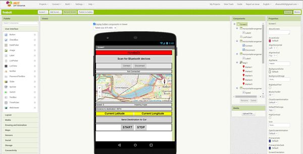
| + | The MIT App inventor 2 is an open-source web application available for free use to develop basic android mobile applications. It circumvents the need to program and develop applications using Java or Kotlin by providing block-based coding and UI development features. It uses a Graphical user Interface (GUI) like the Scratch programming language. Anyone using the web-app would just need to drag and drop blocks to design the UI and use functional blocks to develop logic, functions and flow control. | ||
| + | |||
| + | MIT App inventor for android was originally developed by Google and released in 2010. The development team was led by Hal Abelson and Mark Friedman. “In the second half of 2011, Google released the source code, terminated its server, and provided funding to create The MIT Center for Mobile Learning, led by App Inventor creator Hal Abelson and fellow MIT professors Eric Klopfer and Mitchel Resnick. The MIT version was launched in March 2012.” | ||
| + | App Inventor has a mobile application called the MIT AI Companion app which can be used to download a server cached version of your app under development. This makes it extremely easy and convenient to test intermediate functions and bug testing as changes can be observed in real-time. Once done with the development, users can download a “.apk” file after building. This is an installable file for the android OS which allows the user to test their app as a standalone android app. | ||
| + | |||
| + | The Web app provides two important sections for mobile app development: | ||
| + | <li>The Designer page</li> | ||
| + | <li>The Blocks page</li> | ||
===User Interface=== | ===User Interface=== | ||
| + | <br/> | ||
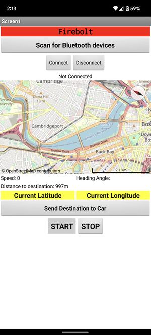
| + | <li style="display: inline-block;"> [[File: App UI.jpeg|center|300px|thumb|App User Interface]]</li> | ||
| + | <br/> | ||
| + | |||
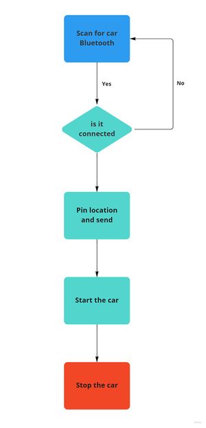
| + | <li style="display: inline-block;">[[File: App_flowchart.jpeg|center|300px|thumb|Flow of the App]] </li> | ||
| + | <br/> | ||
| + | |||
| + | |||
| + | <br/> | ||
| + | <li style="display: inline-block;">[[File: MIT_app_inventor.jpeg|left|600px|thumb|UI development page - the “Designer page”]] </li> | ||
| + | |||
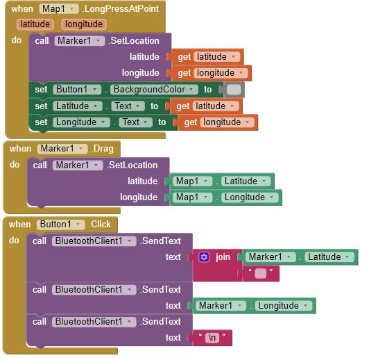
| + | <li style="display: inline-block;">[[File: MIT_app_inventor_backend.jpeg|right|600px|thumb|Function and flow development page - the “Blocks page”]] </li> | ||
| + | <br/> | ||
| + | |||
| + | === Bluetooth Block === | ||
| + | |||
| + | The firebolt app uses the bluetooth client block to establish a connection with the HC-05 bluetooth module onboard the car. It is necessary to establish connection and connect to a bluetooth pair to send and receive messages. | ||
| + | |||
| + | <li style="display: inline-block;">[[File: bluetooth_block.jpeg|right|600px|thumb|MIT App inventor block to connect and disconnect from a bluetooth devic]] </li> | ||
| + | <br/> | ||
| − | === | + | === Map and Marker Blocks === |
| + | |||
| + | The map block is used to create and display a 2D map of the world for location, navigation and other map functions. It uses an open-source map library which is very similar to Google Maps. The Map bloc has several functions including display, zoom, direction, distance, coordinate calculation. Fireblot uses this block to locate a destination location for the car and send the corresponding latitude and longitude values. This is made possible by the marker block. Markers can be placed on any location on the map and the pinpointed location coordinates can be received as floating point integers. These values are displayed on the app and also used to send as a bluetooth message to the HC-05 module when required. | ||
| + | |||
| + | <li style="display: inline-block;">[[File: maps_and_markers.jpeg|right|600px|thumb|Map and Marker blocks used in the firebolt app. ]] </li> | ||
| + | |||
| + | === Testing and Downloading === | ||
| + | |||
| + | MIT App inventor projects can be accessed for testing on the MIT AI companion app or built into a downloadable APK file. It can also be exported as a file to be later imported. The file extension for an app inventor project is “.aia”. | ||
| + | |||
| + | ==Bluetooth== | ||
| − | + | Gitlab link: https://gitlab.com/Ritika_Beniwal_/firebolt/-/tree/Bluetooth_and_app | |
| + | <br> | ||
| + | |||
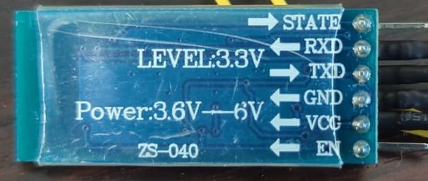
| + | The HC-05 module is an easy to use bluetooth module that can be used to interface with devices using its Serial Port Protocol. Bluetooth is used for wireless network transmission of data. The HC-05 has several features: | ||
| + | <li>UART interface with programmable baud rate </li> | ||
| + | <li>With integrated antenna </li> | ||
| + | <li>Auto-connect to the last device on power as default. </li> | ||
| + | <li>Can act as a slave or master device for transmission</li> | ||
| − | = | + | <br> |
| + | <li style="display: inline-block;">[[File: bluetooth_module.jpeg|right|600px|thumb|The HC-05 bluetooth module. ]] </li> | ||
| + | <br> | ||
| − | + | The AT commands allow the module to have a modifiable set of characteristic parameters. This can be achieved by enabling the EN pin on the module and serially sending some strings based on the requirement. When on the default mode, the module shows upon other device scans for bluetooth devices under the identifier "HC-05". To begin using serial transmission, you first need to pair the module to your device. During the pairing process, the password request encountered should be expecting one of the default passwords "1234" or "0000". You can change this password using one of the AT commands. | |
| + | === Technical Challenges and solutions=== | ||
| + | <li>Some initial challeneges we faced while using the bluetooth module is trying to pair it certain smartphones. It sometimes did not show up on any bluetooth scan list even though it was powered on and working with some other devices. We later found out that the module can sometimes take a long time to become an available slave device again. We fixed this problem by making sure the device previously connected to it, disconnected before trying a new device.</li> | ||
| + | <li>We also had issues while sending out and receiveing data from the smartphone app. Since the UART queue by default accepts only string we decided to send all information from the app as a string. We then parsed the string to extract data.</li> | ||
<BR/> | <BR/> | ||
<HR> | <HR> | ||
| Line 1,055: | Line 1,419: | ||
== Conclusion == | == Conclusion == | ||
| + | This is not a project where only writing best code for our controller is not good enough. This project tests overall personality. As a team we were not prepared to spend more time on this and due to some mismanagement we were always falling behind. But we tried our best to complete the project with few team members. We learnt different aspect of a product development: | ||
| + | * People Management: We were more focused on our node but review is equally important. Well defined roles and responsibilities will contribute to the success and timely completion of the project. | ||
| + | * Finance Management: We bought components just by referring the previous years project. Before ordering we should have read the proper descriptions and then order according to requirement. There was another mistake which should have been avoided was we should have ordered some spare components like voltage regulators, batteries, SJ2 board. Few components got damaged and without figuring out problems we were only ordering and repeating the same mistake. | ||
| + | * Software skills: We learnt CAN protocol and Unit testing. The Unit tested modules gave us the confidence. The most important aspect that we learnt, don't trust the software which failed even one time out of hundred times, it has potential to bring you back to the starting point. | ||
| + | * Time Management: Well defined agenda for every week to test and develop could have made our tasks easier. Doing some home work before coming for the team meeting may have helped us to complete the project before time giving us time for more integration testing. Team meetings are meant to discuss problems and do integration. | ||
| + | |||
| + | |||
| + | Looking back, we could have probably created a better plan earlier on. Defining milestones for different nodes, and if they were not reached, shift our attention to get them done to progress the overall project. We overlooked a lot of the mechanical aspects of the RC car and how it would impact the compass and accelerometer. Improving our mounting and spending more time refining the process of determining heading would have likely helped a lot. Refining driver logic to deal with some variability in steering, that we did not notice until integration testing near the final weeks, earlier on could also have helped in the performance of the car in the final demo. These are learning points that we will keep in mind for future projects and add to the takeaways from the course. | ||
| + | |||
| + | We did our hardware setup much later, we wasted a lot of time in doing connections again and again. A better strategy would have been to get familiar with hardware connections and make a prototype setup to complete the milestones. We were waiting for PCB, which till the end was not completed and had some issues. It was a complete hassle to finalize our hardware in the end and test individual modules again. We got very less time for integration testing, our Geo navigation could have done much better if we would have done proper integration testing. | ||
=== Project Video === | === Project Video === | ||
| + | https://youtu.be/lGZTV-ZGHd8 | ||
| + | === Project Source Code === | ||
| + | https://gitlab.com/ritupatil1/firebolt/-/tree/master | ||
| − | + | https://gitlab.com/Ritika_Beniwal_/firebolt/-/tree/master | |
=== Advise for Future Students === | === Advise for Future Students === | ||
* Get started early and make your hardware stable as early as possible so that you have enough time for extensive testing of the software. Because without on field testing corner cases and potential problems in the code can't be determined. | * Get started early and make your hardware stable as early as possible so that you have enough time for extensive testing of the software. Because without on field testing corner cases and potential problems in the code can't be determined. | ||
| − | * | + | * Make use of the holidays and spring break. If you have your basic framework of the software and hardware completed by the end of spring break you can start testing ASAP. |
| − | * | + | * Start researching as soon as possible and collect all the information related to the module that has been assigned to you, as there is no single book or manual to refer to. Go through all the problems faced by previous teams as they are a treasure trove of information. If you are facing a problem, it is very likely that some team in previous semesters has faced it. It will save you some precious days. |
| + | *Make sure to get a power supply which gives a steady 5V and 1A current so you don't lose boards due to sudden power surge. When all the car's subsystems are running, the current draw may be higher than expected. Make sure to have a common ground for all the components related to a single ECU. | ||
| + | *The most critical hardware connection is for motor node. We used the receiver , which we used to calibrate the ESC for Servo, DC and RPM power supply. We did that 1 week before our demo, and the motor node was fine. | ||
| + | * Can Transceiver: Our CAN bus data was not coming on Bus Master but every node was receiving the data, we were using same module which previous groups used. Later we found out the termination was the problem. Each Can transceiver had 120 ohm resistor. Debugging without Bus Master was a nightmare. | ||
| + | * It is always better to buy new and quality components. The RC Car performance depends on what components you are using. The better and reliable components makes your life easier. | ||
=== Acknowledgement === | === Acknowledgement === | ||
| + | |||
| + | We want to express our gratitude to Professor Preetpal Kang for sharing valuable inputs and knowledge throughout the duration of the project. We would also like to thank the project groups of previous years, which helped us to avoid the mistakes made by them which that we saved some time to understand the concepts better. | ||
=== References === | === References === | ||
http://socialledge.com/sjsu/index.php/Industrial_Application_using_CAN_Bus | http://socialledge.com/sjsu/index.php/Industrial_Application_using_CAN_Bus | ||
| − | + | ||
| + | Bridge Sensor ECU | ||
| + | *[https://www.mpja.com/download/hc-sr04_ultrasonic_module_user_guidejohn.pdf HCSR-04] | ||
| + | |||
| + | Motor ECU | ||
| + | * https://www.youtube.com/watch?v=-26ZSgDqwQQ&ab_channel=Traxxas | ||
| + | * https://www.youtube.com/watch?v=ix-J85uRFjE&ab_channel=Traxxas | ||
| + | |||
| + | Geographical ECU | ||
| + | *[https://www.igismap.com/formula-to-find-bearing-or-heading-angle-between-two-points-latitude-longitude/ Bearing Formula] | ||
| + | *[https://www.igismap.com/haversine-formula-calculate-geographic-distance-earth/ Haversine Formula] | ||
| + | *https://cdn-shop.adafruit.com/product-files/1059/CD+PA1616D+Datasheet+v.05.pdf | ||
| + | *[https://www.pololu.com/file/0J434/LSM303DLH-compass-app-note.pdf Compass Heading Tilt Compensated] | ||
| + | |||
| + | |||
| + | Mobile Application | ||
| + | * http://ai2.appinventor.mit.edu/ | ||
| + | * https://www.youtube.com/watch?v=aQcJ4uHdQEA | ||
Latest revision as of 06:54, 11 June 2022
Contents
Abstract
Firebolt is battery powered autonomous RC car. The car uses four microcontrollers for communication between the nodes- driver node, motor node, bridge & sensor node, and geological node over the CAN bus. It is interfaced to the mobile application which sends GPS coordinates for the destination location to the driver node and reaches the destination by avoiding any obstacles that comes in the path. For obstacle detection and avoidance it uses Ultrasonic Sensor and makes the decision of steering and maintaining speed after performing calculations based on the bridge and sensor node's data.
Objectives & Introduction
Objectives
The objective of this project is to get hands on experience of application of embedded systems in autonomous vehicles, have understanding of CAN bus communication, CAN database files, TDD and other related tools such as PCAN dongle and Busmaster.
Software side
- The car communicates with an Android application
- Receive coordinates from gps to drive itself to the destination while avoiding obstacles
- Display useful information on the LCD
- Take care of elevation and make correct speed decisions
- DBC file for all the nodes
Hardware side
- Design PCB for four controllers and other necessary components
- Choose good options for mounting the ultrasonic sensors on the car
- Make a good GUI Android application for interfacing with the microcontroller
Introduction
The controllers for the project are divided in 5 parts. Each controller has different tasks and communicate with each other over CAN bus.
- Driver Node
- GEO Node
- Sensors and Bridge Node
- Motor Node
- Mobile Application
Team Members & Responsibilities
Priyanka Rai LinkedIn'
- Geo Controller
- GPS and Compass Interfacing
- Integration Testing
- Wiki Page Update
Ritu Patil LinkedIn'
- Motor Controller
- RPM Sensor
- Integration Testing
- Wiki Page Update
Ritika Beniwal LinkedIn'
- Driver Node
- LCD interfacing
- Integration Testing
- Wiki Page Update
Utsav Savaliya LinkedIn'
- Sensor Controller
- Integration Testing
- Wiki Page Update
- Bluetooth integration with Sensor
Dhanush Babu LinkedIn'
- Bluetooth module interfacing
- Motor Controller
- Android App
- Integration Testing
Schedule
| Week# | Start Date | Target Date | Task | Completion Date | Status |
|---|---|---|---|---|---|
| Week 1 |
|
|
|
|
|
| Week 2 |
|
|
|
|
|
| Week 3 |
|
|
|
|
|
| Week 4 |
|
|
|
|
|
| Week 5 |
|
|
|
|
|
| Week 6 |
|
|
|
|
|
| Week 7 |
|
|
|
|
|
| Week 8 |
|
|
|
|
|
| Week 9 |
|
|
|
|
|
| Week 10 |
|
|
|
|
|
| Week 11 |
|
|
|
|
|
| Week 12 |
|
|
|
|
|
Parts List & Cost
| Item# | Part Desciption | Vendor | Qty | Price($) |
|---|---|---|---|---|
| 1 | RC Car | Traxxas [1] | 1 | 280 |
| 2 | CAN Transceivers MCP2551-I/P | Comimark [2] | 5 | 8.99 |
| 3 | Ultrasonic Sensors | Max Botix[3] | 4 | 24.95 |
| 4 | GPS Breakout Board | Adafruit[4] | 1 | 29.95 |
| 5 | GPS Antenna | Adafruit[5] | 1 | 19.95 |
| 6 | RPSMA female to mhf4 | Superbat[6] | 1 | 7.99 |
| 7 | HC05 bluetooth RF Transceiver | HiLetgo[7] | 1 | 15.99 |
| 8 | Triple-axis Accelerometer | Adafruit[8] | 1 | 14.95 |
| 9 | Traxxas RPM Sensor | Traxxas[9] | 1 | 13.76 |
| 10 | Traxxas Battery and Charger | Traxxas[10] | 1 | 62.95 |
| 11 | Voltage Regulator | Valefod[11] | 6 | 10.99 |
| 12 | Headlights | Hobbypark[12] | 1 | 7.96 |
Printed Circuit Board
Initially we started our testing with mounting all our hardware on the breadboard (yes, it was messy and unstable!).
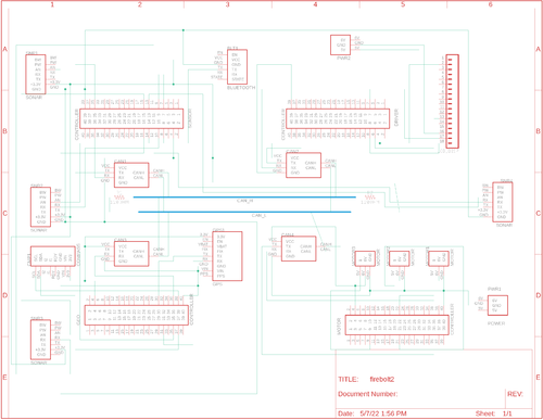
PCB Schematic
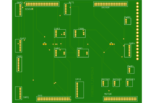
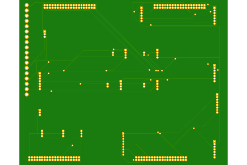
PCB Board
Challenges
- Since there are four controllers and a significant number of components (gps, sensors, can transceivers, volt regulator etc.) it was difficult for us to keep our hardware stable because every time we go for field testing some will get disconnected and we were kind of stuck up in the hardware setup.
- We decided to get the PCB printed but there were some issues and resolving them and getting a new PCB would take time.
Solution
- Finally we decided to use the prototype board for mounting all the components and stabilizing our hardware.
CAN Communication
We used controller area network to communicate data between four nodes. All nodes are connected to each other through a physically conventional two wire bus CANH and CANL. The wires are a twisted pair with 120 Ω termination resistors at each end of the bus. 1s and 0s are transmitted as CAN High(0V difference) and Can Low(2v difference). A CAN frame has the following contents:
- Data Length Code (4bits)
- Remote Transmission Request.
- ID extend bit.
- Message ID (11 bit or 29 bit)
- Data bytes( depends on DLC)
- CRC
Arbitration: No two nodes will transmit at the same time because of arbitration. A lower Message-ID has a Higher priority on the CAN bus since 0 is the dominant bit.
Bit Stuffing: CAN bus stuffs extra bits when a long chain of multiple 1's or 0's occur to improve CAN integrity.
DBC File
The DBC file is a simple text file that consists of information for decoding raw CAN bus data to physical values or in human readable form.
| Sr. No | Message ID | Message function | Receivers |
|---|---|---|---|
| Driver Heartbeat | |||
| 1 | 100 | Driver Heartbeat | Motor, Sensor, Geo |
| Start Stop signal from Android app to Driver | |||
| 1 | 101 | Bridge Sensor | Driver |
| Ultrasonic sensors data transmit | |||
| 2 | 200 | Sensor sonars from front, back, left ,right sensor | Driver |
| Destination Location | |||
| 4 | 250 | Bridge Sensor | Geo |
| Driver to Motor Command | |||
| 5 | 300 | Speed and steering direction for the motor | Motor |
| Geo Controller | |||
| 6 | 400 | Bearing, Heading and Distance | Driver |
| Motor Controller | |||
| 7 | 600 | Motor speed | Driver |
| Debug messages | |||
| 8 | 700 | Driver Debug | BRIDGE_SENSOR,MOTOR,GEO |
| 9 | 750 | Geo Debug | BRIDGE_SENSOR,MOTOR,DRIVER |
VERSION ""
NS_ :
    BA_
    BA_DEF_
    BA_DEF_DEF_
    BA_DEF_DEF_REL_
    BA_DEF_REL_
    BA_DEF_SGTYPE_
    BA_REL_
    BA_SGTYPE_
    BO_TX_BU_
    BU_BO_REL_
    BU_EV_REL_
    BU_SG_REL_
    CAT_
    CAT_DEF_
    CM_
    ENVVAR_DATA_
    EV_DATA_
    FILTER
    NS_DESC_
    SGTYPE_
    SGTYPE_VAL_
    SG_MUL_VAL_
    SIGTYPE_VALTYPE_
    SIG_GROUP_
    SIG_TYPE_REF_
    SIG_VALTYPE_
    VAL_
    VAL_TABLE_
BS_:

BU_: DRIVER MOTOR BRIDGE_SENSOR GEO DEBUG

BO_ 100 DRIVER_HEARTBEAT: 1 DRIVER
  SG_ DRIVER_HEARTBEAT_cmd : 0|8@1+ (1,0) [0|0] "" BRIDGE_SENSOR,MOTOR,GEO

BO_ 101 DRIVE_STATUS: 1 BRIDGE_SENSOR
  SG_ DRIVE_START_STOP : 0|8@1+ (1,0) [0|0] "" DRIVER

BO_ 200 SENSOR_SONARS: 5 BRIDGE_SENSOR
 SG_ SENSOR_SONARS_left : 0|10@1+ (1,0) [0|0] "cm" DRIVER
 SG_ SENSOR_SONARS_right : 10|10@1+ (1,0) [0|0] "cm" DRIVER
 SG_ SENSOR_SONARS_middle : 20|10@1+ (1,0) [0|0] "cm" DRIVER
 SG_ SENSOR_SONARS_rear : 30|10@1+ (1,0) [0|0] "cm" DRIVER

BO_ 250 DESTINATION_LOCATION: 8 BRIDGE_SENSOR
 SG_ DEST_LATITUDE : 0|28@1+ (0.000001,-90.000000) [-90|90] "degrees" GEO
 SG_ DEST_LONGITUDE : 28|28@1+ (0.000001,-180.000000) [-180|180] "degrees" GEO

BO_ 300 DRIVER_TO_MOTOR: 2 DRIVER
SG_ DRIVER_TO_MOTOR_speed : 0|8@1+ (1,0) [-30|30] "kmph" MOTOR
 SG_ DRIVER_TO_MOTOR_direction : 8|8@1- (1,-2) [-2|2] "degrees" MOTOR

BO_ 400 GEO_CONTROLLER_COMPASS: 8 GEO
  SG_ HEADING : 0|12@1+ (0.1,0) [0|359.9] "degrees" DRIVER, BRIDGE_SENSOR
  SG_ BEARING : 12|12@1+ (0.1,0) [0|359.9] "degrees" DRIVER,BRIDGE_SENSOR
  SG_ DISTANCE_TO_DESTINATION: 24|32@1+ (0.01,0) [0|359.9] "meters" DRIVER,BRIDGE_SENSOR

BO_ 600 MOTOR_SPEED: 2 MOTOR
SG_ MOTOR_SPEED_info : 0|8@1+ (0.1,-10) [-10|10] "kmph" DRIVER, BRIDGE_SENSOR


BO_ 700 DRIVER_DEBUG: 2 DEBUG
  SG_ car_driving_status: 0|8@1+ (1,0) [0|0] "" DEBUG
  SG_ car_steering_status: 8|8@1+ (1,0) [0|0] "" DEBUG

BO_ 750 GEO_CONTROLLER_DEBUG_MESG: 10 DEBUG
 SG_ CURR_LATITUDE : 0|28@1+ (0.000001,-90.000000) [-90|90] "degrees" DEBUG
 SG_ CURR_LONGITUDE : 28|28@1+ (0.000001,-180.000000) [-180|180] "degrees" DEBUG
 SG_ RAW_HEADING : 56|12@1+ (0.1,0) [0|359.9] "degrees" DEBUG

CM_ BU_ DRIVER "The driver controller driving the car";
CM_ BU_ MOTOR "The motor controller of the car";
CM_ BU_ SENSOR "The sensor controller of the car";
CM_ BO_ 100 "Sync message used to synchronize the controllers";
CM_ BU_ GEO "To provide raw GPS and compass heading";
CM_ SG_ 100 DRIVER_HEARTBEAT_cmd "Heartbeat command from the driver";

VAL_ 300 DRIVER_TO_MOTOR_direction -2 "MOTOR_direction_HARD_LEFT" -1 "MOTOR_direction_SOFT_LEFT" 0 "MOTOR_direction_STRAIGHT" 1 "MOTOR_direction_SOFT_RIGHT" 2 "MOTOR_direction_HARD_RIGHT" ;
VAL_ 700 car_steering_status 2 "RIGHT" 1 "LEFT" 0 "STRAIGHT";
VAL_ 700 car_driving_status 2 "BACKWARD" 1 "FORWARD" 0 "STOPPED";
Technical Challenges
- The CAN transceivers that we bought had inbuilt 120 ohm resistor each, which we didn't notice. And every time we interfaced all the four nodes the data won't show up in the busmaster software. We found this very late and until then we thought it's hardware/dbc file issue and wasted potential amount of time in debugging.So we de-soldered those termination resistors and we were able to see our data smoothly on busmaster.
- As an advice, make sure at the end of all four nodes after adding termination resistors of 120 ohm on both sides, the resultant resistance is 60 ohms. Only then all four nodes can communicate over CAN bus.
Sensor and Bluetooth ECU
Hardware Design
The obstacle detection sensors used here are Ultrasonic sensors. The HRLV-MaxSonar-EZ1 sensors from MaxBotix are used here. In these sensors there is membrane which needs to be triggered in order to generate and send ultrasonic waves every few seconds. When ultrasonic waves collide and come back and strikes with this membrane a pulse is generated which is used for sensing.
| Sl No. | SJ2 board Pin No. | Ultrasonic sensor Pin No. | Function |
|---|---|---|---|
| 1. | ADC Pin 1.30 | AN(Front left sensor) | Input to ADC channel 4 |
| 2. | ADC Pin 1.31 | AN(Front right sensor) | Input to ADC channel 5 |
| 3. | ADC Pin 1.26 | AN(Front sensor) | Input to ADC channel 3 |
| 4. | ADC Pin 1.25 | AN(Rear sensor) | Input to ADC channel 3 |
| 5. | GPIO Pin 0.6 | Rx(Front left sensor) | Triggering pulse for left sensor |
| 6. | GPIO Pin 0.8 | Rx(Front right sensor) | Triggering pulse for right sensor |
| 7. | GPIO Pin 0.9 | Rx(Front sensor) | Triggering pulse for front sensor |
| 8. | GPIO Pin 0.7 | Rx(Rear sensor) | Triggering pulse for rear sensor |
Apart from the pin connections for the Sensor node the important thing is to mount the sensors at particular angles. The angle placement is critical for left and right sensor as we faced lot of problems while detecting the walls. We chose the angle by error and trial method by simply placing the sensors at different angles. We tried keeping the angle above the 45 degrees so that to provide wider angle for the obstacles to detect.
Software Design
The sensor node has to receive values from all the sensors and send the distance values on the CAN bus for the driver to run the obstacle avoidance logic.
Receive sensor values
Four sensors are used here. Three in the front and one at the rear side. We need four ADC channels to address the receiving from all sensors. In order to use four pins on the SJ2 board we need to set the pins to analog mode. In the adc.h file and adc.c file there are only three channels initialized, so one needs to add ADC channel 3 in these files. On how to use these sensors, the datasheet of helped a lot. It addresses every aspect of how to use this particular sensor and the solution to most of the problem that can arise. All the sensor raw values are digitally converted in the range of 0 to 1024( 10 bit ADC). These value is in inches as mentioned in the datasheet. So, one needs to convert it into centimeter by applying some formula. The formula can be different based on the configuration used to setup the ADC channel even if same sensor is used.
Sending sensor values in terms of distance to CAN
The raw values coming from the sensor needs to be filtered before sending on the CAN bus. The more information about filtering is mentioned in the techical challenges section. The below diagram shows the detailed flowchart of software design implemented for the sensor node.
Technical Challenges
- The main challenge while using ultrasonic sensor with this particular project is of crosstalk. While detecting objects in the front all the front sensors waves are interfering with each other giving false values in the left or right sensor while the object is in the front only. The datasheet addresses this issues and what to do when multiple sensors are used in a system. It says that trigger each sensor are different time period in order to avoid crosstalk. So we triggered the front and rear at one particular time and left and right at one particular time. One sequence is triggered at particular 10Hz and other sequence is triggered at another 10Hz. There is a division of callbacks counts in 100Hz and a lock mechanism is used in order to used different 20Hz period out of 100Hz.
- For frequency noise measurements like when the values suddenly change or vary between certain range sometimes, a filter is implemented. The most common filter for this type of use is median filter where a series of values are stored in a array and median is taken of all the values stored in that array.
Motor ECU
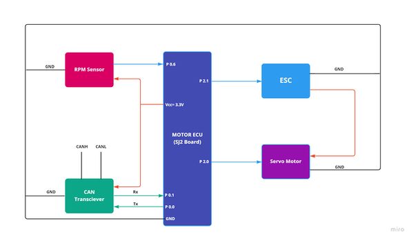
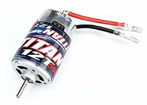
The Motor ECU acts as an encoder for the DC motor (used for propulsion) and Servo motor (used for turning the axle and changing direction of the car). The car is a two wheel drive with DC motor connected to the rear wheels and the servo motor is connected to the front wheels. The DC motor is controlled by Electronic Speed Control. The ECU supplies PWM signal to the ESC and the ESC powers the DC motor. The Servo motor is powered by the car battery as well and gets its PWM signal from the ECU. The RPM sensor sends its output to motor ECU by which the actual speed of the wheels is calculated.
Hardware Design
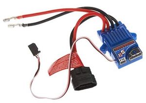
ESC & DC MotorThe DC motor is controlled by ESC using PWM signals provided by the motor controller for forward and reverse movements. We used the 9v NiMH battery to power up the ESC. The DC motor is powered by the ESC which has a dc-to-dc converter which converts 9v to 6v. The output from the ESC is used to power the Servo motor. ESC has an ease set button which is used for calibration and setting different modes for the car. The car can be operated in the following 3 modes:
As we desire to run the car at full throttle, Sport mode is being used. The frequency of the PWM signal fed to the servo motor is 100Hz. Based on the duty cycle set by the user, the car will go forward, reverse, or neutral.
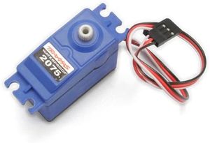
Servo MotorWe are using Traxxas 2075 for this project which came with the car and it is responsible for steering the car. It takes the 6V power directly from ESC. The servo motor is controlled directly from the SJ2 micro-controller board. The PWM signal is supplied at a frequency of 100 Hz. Based on the duty cycle of the signal sent to the servo, the direction of servo motor can be changed: PWM 10 to 14.9 for turning left.
Software DesignAt startup the motor is initialized by giving a neutral PWM signal for 3s and the interrupt for the rpm sensor input is setup as well. The motor receives angle for steering and speed in a single CAN message from the driver ECU. After receiving the command the speed value is converted into corresponding value of PWM by increasing or decreasing neutral PWM value in steps of 0.01. The physical value of the motor speed is compared to the speed received from the driver and it is reduced or increased to match with the desired speed. For reverse a PWM of 14.5 is given to smoothly reverse the car. The direction of the car is set according to the value of ENUM received from the driver ECU. For navigation the car takes soft turns and when and obstacle is detected it takes hard turns to avoid collisions. The period_callbacks__initialize() function calls the following functions:
The period_callbacks__1Hz() function calls the following function:
The period_callbacks__10Hz() function calls the following functions:
Technical Challenges
Geographical And Bridge ControllerHardware DesignThe Geographical controller does the processing for compass data and GPS data. After processing the data for heading ,bearing and distance to destination , the controller sends these data over can bus to the Driver node. The GPS module is interfaced with SJ2 board using UART. SJ2 board gets the data (NMEA string) for GPS coordinates processing. The controller sends the command to GPS module to filter the string and only send GPGGA string. The Compass module is interfaced over I2C to find the heading for car navigation. The CAN transceiver uses port 0 (can1) of the SJ2 board.
Software DesignThe GEO controller consisted of 4 main parts which are:
OverviewThese code modules, calculate compass heading degree, bearing, parse GPS coordinates, calculate the checkpoints the RC car has to go through when navigating to a destination, send distance to destination to driver node, and handle messages received on the CAN bus. The period_callbacks__initialize() function calls the following functions:
The period_callbacks__1Hz() function calls the following function:
The period_callbacks__10Hz() function calls the following functions:
GPS
In the gps__run_once_10Hz() the GPS is initially configured once to disable all NMEA messages except GPGGA which is message chosen to parse the coordinates and GPS lock.
The GPS module constantly transmits NMEA GPGGA messages over UART to the SJ2 MCU. These messages which come in the form of a string are stored character by character in the line
buffer until a new line character which indicates the end of string. The stored string is then extracted from the line buffer. The extracted line is then tokenized to parse the
latitude, latitude direction, longitude, longitude direction, and fix quality. South and West directions are also properly handled to make the latitude and longitude negative
values.
Although the GPS module has fix indication , but GPGGA string has field for FIX status also. Getting the Fix/Lock status using the string is much easier than using GPIO pins to get
the Lock status using FIX led of the GPS module. The Lock status/flag was used as a condition to calculate the bearing and checkpoints only when the GPS had a lock meaning that the
current coordinates were valid.
Compass
The compass initialization configures the LSM303DLHC magnetometer and accelerometer registers over I2C bus to default settings using default gain and single mode.
The compass heading degree is computed by using the tilt compensation algorithm and the pitch and roll values of LSM303DLHC accelerometer. The tilt compensation algorithm ensures
that the values of the compass heading are precise. The formulae used to calibrate the compass are mentioned below:
pitch = asin(-acc_x / sqrt(acc_y * acc_y + acc_z * acc_z + acc_x * acc_x))
 mag_x = mag_x * cos(pitch) + mag_z * sin(pitch)
 mag_y = mag_y * cos(roll) + mag_x * sin(roll) * sin(pitch) - mag_z * sin(roll) * cos(pitch)
 mag_z = -mag_x * cos(roll) * sin(pitch) + mag_y * sin(roll) + mag_z * cos(roll) * cos(pitch)
heading = atan2(mag_y, mag_x) * r2d
r2d is radian to degree conversion function
This heading is calculated in radians since atan2 returns a value between -π and +π. Therefore, before converting the heading into degrees the value needs to be normalized to put it in the range from 0 to 360 degrees. CheckpointsIn real world, the source and destination are not on a straight line. The car has to find the best possible and smallest route to its final destination. In this project keeping that in mind we have used checkpoint algorithm. These waypoints are known coordinates which are given according to the destination and source path. The car needs to follow the route determined by the waypoints from source to destination. We choose 10 points over a known location and hardcoded these coordinates in GEO node logic. Once our car gets the destination coordinates from Bridge and Sensor controller, it starts giving Heading , Bearing and Distance values to Driver Node. This waypoint must satisfy the below conditions:
So when the algorithm finds the destination coordinates, then bearing is calculated with that particular coordinate, so that car can be further instructions to move towards that particular point. As shown in the figure below, our algorithm keeps finding new coordinates with time (orange ones) and at last go to the final destination coordinates. The algorithm is mentioned below in the form of flowchart and code: The way point calculation determines the nearest way point continuously by computing the distance using Haversine formula and current location using GPS. The heading and bearing is also computed using the Haversine formula and is sent over the CAN bus for heading correction.* Alternatively, once the car is within the threshold distance, next way point is selected and the car heads to the next way point. To calculate the geographical distance between the two points the haversine formula was used which is called periodically from the waypoints.c module. Below is the formula used: a = sin²(ΔlatDifference/2) + cos(lat1) * cos(lt2) * sin²(ΔlonDifference/2) c = 2 * atan2(sqrt(a), sqrt(1−a)) d = R * c
The bearing which is the angle towards our desired destination is computed using the formulas below referenced at this link. X = cos θb * sin ∆L Y = cos θa * sin θb – sin θa * cos θb * cos ∆L β = atan2(X,Y)
The bearing is also calculated in radians since atan2 returns a value between -π and +π. Therefore, before converting the heading into degrees the value needs to be normalized to put it in the range from 0 to 360 degrees. The calculated bearing is then sent to the driver node which use the compass heading degree and the bearing to align the car toward the target destination. Technical Challenges
Driver NodeDriver Node is the master controller. It receives input from sensor and bridge node, processes it to make right decision for controlling the speed and steering direction of the car and then commands the motor node to drive accordingly. This node is also interfaced to the LCD, which acts as dashboard of the car and displays information such as car speed and distance to destination on the screen. HardwareLCD is interfaced with the SJ2 board and it communicates over UART. P4.28 and P4.29 which is UART3 on board is used. Headlights and Tailights are also connected to the driver node using four GPIOs. Software Architecture Driver Logic
Obstacle Avoidance Logic
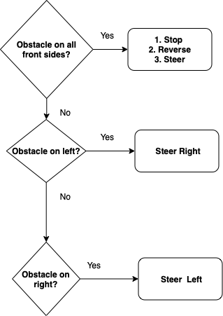
if (obstacle_on_all_front_sides()) {
          stop_the_car();
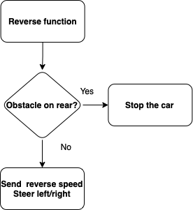
          reverse_car_and_steer();
        } else if (obstacle_on_left() && obstacle_in_right() && (!obstacle_on_front())) {
          drive_forward();
        } else if (obstacle_on_left() && (!obstacle_in_right())) {
          obstacle_on_right = false;
          get_steering_range(obstacle_on_right); // right steer
        } else if (obstacle_in_right() && (!obstacle_on_left())) {
          obstacle_on_right = true;
          get_steering_range(obstacle_on_right); // left steer
        } else if (obstacle_on_front() && (!obstacle_on_left() && !obstacle_in_right())) {
          stop_the_car();
          reverse_car_and_steer();
          obstacle_on_right =
              (internal_sensor_data.SENSOR_SONARS_right < internal_sensor_data.SENSOR_SONARS_left) ? true : false;
          get_steering_range(obstacle_on_right);

        } else if (obstacle_on_rear() && (!obstacle_on_all_front_sides())) {
          obstacle_on_right =
              (internal_sensor_data.SENSOR_SONARS_right < internal_sensor_data.SENSOR_SONARS_left) ? true : false;
          get_steering_range(obstacle_on_right);
          debug_values.car_driving_status = FORWARD;
          debug_values.car_steering_status = STRAIGHT;
        } else {
          stop_the_car();

          debug_values.car_driving_status = STOPPED;
          debug_values.car_steering_status = STRAIGHT;
        }
  if (obstactle_on_right == true) {
    motor_signal.DRIVER_TO_MOTOR_direction = MOTOR_direction_HARD_LEFT;
    motor_signal.DRIVER_TO_MOTOR_speed = ideal_speed;
    if (obstacle_in_right_far()) {
      motor_signal.DRIVER_TO_MOTOR_direction = MOTOR_direction_SOFT_LEFT;
      motor_signal.DRIVER_TO_MOTOR_speed = ideal_speed;
    } else if (obstacle_in_right_near()) {
      motor_signal.DRIVER_TO_MOTOR_direction = MOTOR_direction_HARD_LEFT;
      motor_signal.DRIVER_TO_MOTOR_speed = reduced_speed;
    }

  } else {
    motor_signal.DRIVER_TO_MOTOR_direction = MOTOR_direction_HARD_RIGHT;
    motor_signal.DRIVER_TO_MOTOR_speed = ideal_speed;
    if (obstacle_on_left_far()) {
      motor_signal.DRIVER_TO_MOTOR_direction = MOTOR_direction_SOFT_RIGHT;
      motor_signal.DRIVER_TO_MOTOR_speed = ideal_speed;
    } else if (obstacle_on_left_near()) {
      motor_signal.DRIVER_TO_MOTOR_direction = MOTOR_direction_HARD_RIGHT;
      motor_signal.DRIVER_TO_MOTOR_speed = reduced_speed;
    }
  }
  motor_signal.DRIVER_TO_MOTOR_speed = ideal_speed;
  // motor_signal.DRIVER_TO_MOTOR_speed = ideal_speed;
}
Reverse and Steer
  if (!obstacle_on_rear()) {
    motor_signal.DRIVER_TO_MOTOR_direction = 0;
    motor_signal.DRIVER_TO_MOTOR_speed = reverse_speed;
    update_lights(10, taillight_left);
    update_lights(10, taillight_right);
  } else {
    stop_the_car();
  }
Driver receives raw heading and bearing from the Geo node and in order to calculate the turning direction, it first computes the difference between heading and bearing. Then based on which quadrant the difference lies and where the destination lies, take navigation decisions to steer left, right or straight.
if (heading_difference >= 350 && heading_difference <= 10) {
    gps_navigation_direction = straight;
    heading_difference = fabs(heading_difference);

    debug_values.car_driving_status = FORWARD;
    debug_values.car_steering_status = STRAIGHT;
  } else if (heading_difference > 180) {
    gps_navigation_direction = left;
    heading_difference = 360 - heading_difference;

    debug_values.car_driving_status = FORWARD;
    debug_values.car_steering_status = LEFT;

  } else if (heading_difference < 0 && heading_difference > -180) {
    gps_navigation_direction = left;
    heading_difference = fabs(heading_difference);

    debug_values.car_driving_status = FORWARD;
    debug_values.car_steering_status = LEFT;
  }

  else if (heading_difference < -180) {
    gps_navigation_direction = right;
    heading_difference = fabs(heading_difference + 360);

    debug_values.car_driving_status = FORWARD;
    debug_values.car_steering_status = RIGHT;
  } else if (heading_difference > 0 && heading_difference <= 180) {
    gps_navigation_direction = right;

    debug_values.car_driving_status = FORWARD;
    debug_values.car_steering_status = RIGHT;
  }
Periodic CallbacksThe period_callbacks__initialize() function calls the following functions: can__bus_initializer(can1); lcd__init(); head_tail_lights_init(); debug_led_init(); The period_callbacks__1Hz() function calls the following function:
  can_bus_handler_tx_debug_messsages(can1);
  static uint8_t count = 0;
  if (count == 0) {
    lcd__communication_init();
  }
  count = 1;
  print_info_on_lcd();
The period_callbacks__10Hz() function calls the following functions: can_bus_handler__process_all_received_messages(can1); can_bus_handler__manage_mia(); can_bus_handler_tx_messages(can1); Technical Challenges
Mobile ApplicationThe MIT App inventor 2 is an open-source web application available for free use to develop basic android mobile applications. It circumvents the need to program and develop applications using Java or Kotlin by providing block-based coding and UI development features. It uses a Graphical user Interface (GUI) like the Scratch programming language. Anyone using the web-app would just need to drag and drop blocks to design the UI and use functional blocks to develop logic, functions and flow control. MIT App inventor for android was originally developed by Google and released in 2010. The development team was led by Hal Abelson and Mark Friedman. “In the second half of 2011, Google released the source code, terminated its server, and provided funding to create The MIT Center for Mobile Learning, led by App Inventor creator Hal Abelson and fellow MIT professors Eric Klopfer and Mitchel Resnick. The MIT version was launched in March 2012.” App Inventor has a mobile application called the MIT AI Companion app which can be used to download a server cached version of your app under development. This makes it extremely easy and convenient to test intermediate functions and bug testing as changes can be observed in real-time. Once done with the development, users can download a “.apk” file after building. This is an installable file for the android OS which allows the user to test their app as a standalone android app. The Web app provides two important sections for mobile app development: User Interface
Bluetooth BlockThe firebolt app uses the bluetooth client block to establish a connection with the HC-05 bluetooth module onboard the car. It is necessary to establish connection and connect to a bluetooth pair to send and receive messages.
Map and Marker BlocksThe map block is used to create and display a 2D map of the world for location, navigation and other map functions. It uses an open-source map library which is very similar to Google Maps. The Map bloc has several functions including display, zoom, direction, distance, coordinate calculation. Fireblot uses this block to locate a destination location for the car and send the corresponding latitude and longitude values. This is made possible by the marker block. Markers can be placed on any location on the map and the pinpointed location coordinates can be received as floating point integers. These values are displayed on the app and also used to send as a bluetooth message to the HC-05 module when required. Testing and DownloadingMIT App inventor projects can be accessed for testing on the MIT AI companion app or built into a downloadable APK file. It can also be exported as a file to be later imported. The file extension for an app inventor project is “.aia”. BluetoothGitlab link: https://gitlab.com/Ritika_Beniwal_/firebolt/-/tree/Bluetooth_and_app
The HC-05 module is an easy to use bluetooth module that can be used to interface with devices using its Serial Port Protocol. Bluetooth is used for wireless network transmission of data. The HC-05 has several features:
The AT commands allow the module to have a modifiable set of characteristic parameters. This can be achieved by enabling the EN pin on the module and serially sending some strings based on the requirement. When on the default mode, the module shows upon other device scans for bluetooth devices under the identifier "HC-05". To begin using serial transmission, you first need to pair the module to your device. During the pairing process, the password request encountered should be expecting one of the default passwords "1234" or "0000". You can change this password using one of the AT commands. Technical Challenges and solutions
ConclusionThis is not a project where only writing best code for our controller is not good enough. This project tests overall personality. As a team we were not prepared to spend more time on this and due to some mismanagement we were always falling behind. But we tried our best to complete the project with few team members. We learnt different aspect of a product development:
We did our hardware setup much later, we wasted a lot of time in doing connections again and again. A better strategy would have been to get familiar with hardware connections and make a prototype setup to complete the milestones. We were waiting for PCB, which till the end was not completed and had some issues. It was a complete hassle to finalize our hardware in the end and test individual modules again. We got very less time for integration testing, our Geo navigation could have done much better if we would have done proper integration testing.
Project VideoProject Source Codehttps://gitlab.com/ritupatil1/firebolt/-/tree/master https://gitlab.com/Ritika_Beniwal_/firebolt/-/tree/master Advise for Future Students
AcknowledgementWe want to express our gratitude to Professor Preetpal Kang for sharing valuable inputs and knowledge throughout the duration of the project. We would also like to thank the project groups of previous years, which helped us to avoid the mistakes made by them which that we saved some time to understand the concepts better. Referenceshttp://socialledge.com/sjsu/index.php/Industrial_Application_using_CAN_Bus Bridge Sensor ECU Motor ECU
Geographical ECU
|
