Difference between revisions of "F13: Line Following Robot"
Proj user4 (talk | contribs) (→Introduction) |
Proj user4 (talk | contribs) (→Schedule) |
||
| Line 59: | Line 59: | ||
== Schedule == | == Schedule == | ||
| − | |||
| − | |||
The proposed schedule lists the tasks to be completed each week. The time frame for each task spans from a Wednesday to the following Tuesday. This time frame format was selected to facilitate project progress discussions with the professor at the end of each weekly lecture held on Tuesday. | The proposed schedule lists the tasks to be completed each week. The time frame for each task spans from a Wednesday to the following Tuesday. This time frame format was selected to facilitate project progress discussions with the professor at the end of each weekly lecture held on Tuesday. | ||
| Line 86: | Line 84: | ||
| align="center"|3 | | align="center"|3 | ||
| align="center"|10/16 to 10/22 | | align="center"|10/16 to 10/22 | ||
| − | | Generate proposed schedule. Begin | + | | Generate proposed schedule. Begin mechanical layout of components. Begin electrical layout of componets. |
| | | | ||
* Generated proposed schedule. | * Generated proposed schedule. | ||
| − | * Began | + | * Began mechanical and electrical layout of components. |
| − | * After beginning the | + | * After beginning the mechanical and electrical layout of components, realized another order was required to obtain additional mounting components. |
* Placed order #4 with Pololu. | * Placed order #4 with Pololu. | ||
|- | |- | ||
| align="center"|4 | | align="center"|4 | ||
| align="center"|10/23 to 10/29 | | align="center"|10/23 to 10/29 | ||
| − | | Complete | + | | Complete mechanical layout of components. Complete electrical layout of components. |
| | | | ||
| − | * Continued | + | * Continued mechanical and electrical layout of components. |
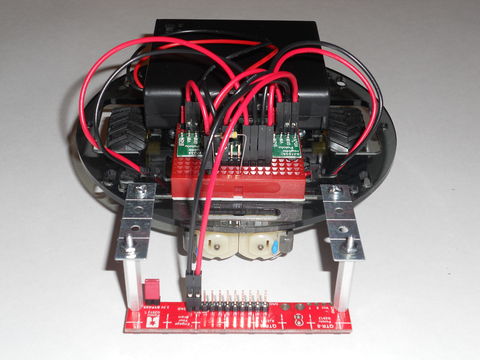
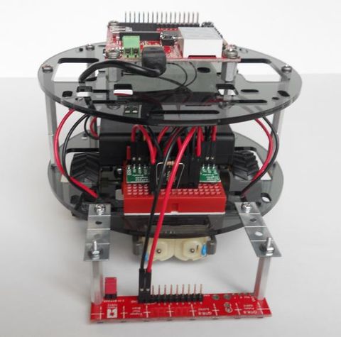
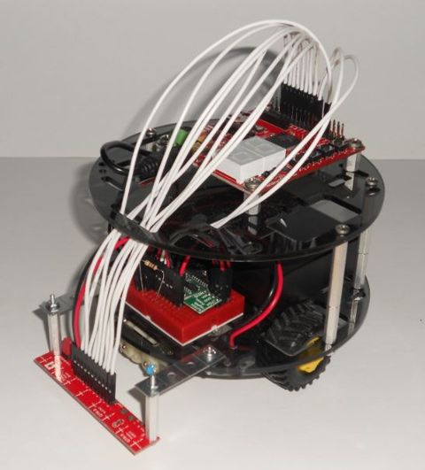
* Encountered issues routing wires from the IR LED Reflectance Sensor Array to the SJ One Board due to physical limitations. | * Encountered issues routing wires from the IR LED Reflectance Sensor Array to the SJ One Board due to physical limitations. | ||
| − | * Reprioritized the | + | * Reprioritized the mechanical and electrical layout of components to be an ongoing task throughout the duration of the project. |
|- | |- | ||
| align="center"|5 | | align="center"|5 | ||
| Line 106: | Line 104: | ||
| | | | ||
* Resolved issues related to routing wires from the IR LED Reflectance Sensor Array to the SJ One Board. | * Resolved issues related to routing wires from the IR LED Reflectance Sensor Array to the SJ One Board. | ||
| − | * Continued | + | * Continued mechanical and electrical layout of components. |
* Completed initial driver revision for the IR LED Reflectance Sensor Array and interfaced it with the SJ One Board. | * Completed initial driver revision for the IR LED Reflectance Sensor Array and interfaced it with the SJ One Board. | ||
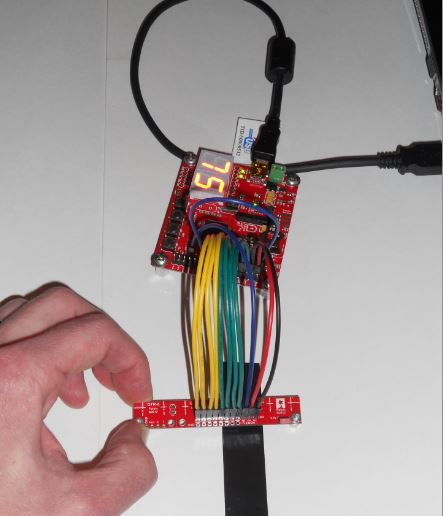
* Tested the IR LED Reflectance Sensor Array driver by passing the array over a black line on a white background and verifying the individual sensors of the array reported the correct readings. | * Tested the IR LED Reflectance Sensor Array driver by passing the array over a black line on a white background and verifying the individual sensors of the array reported the correct readings. | ||
| Line 114: | Line 112: | ||
| Interface SJ One Board with Dual Serial Motor Controller. | | Interface SJ One Board with Dual Serial Motor Controller. | ||
| | | | ||
| − | * Continued | + | * Continued mechanical and electrical layout of components. |
| − | * Completed initial driver revision for the Dual Serial Motor Controller; however, the Dual Serial Motor Controller was not interfaced with the SJ One Board because the required | + | * Completed initial driver revision for the Dual Serial Motor Controller; however, the Dual Serial Motor Controller was not interfaced with the SJ One Board because the required mechanical and electrical infrastructure has not yet been completed. |
* Tested the generation and transfer of motor controller commands by looping back the UART2 TXD2 pin to the UART3 RXD3 pin. The UART2 TXD2 pin will be used to connect to the Dual Serial Motor Controller serial receive input pin. The UART3 RXD3 pin was configured to support motor controller command generation debug efforts. Motor controller commands transmitted on the UART2 TXD2 pin and received on the UART3 RXD3 pin were read from the UART3 receive FIFO and printed to the Hercules serial console to verify their validity. The proper initialization of the UART2 TXD2 pin for serial communication with a 9600 baud rate, 8-bit data, no parity bit, and one stop bit was also verified. | * Tested the generation and transfer of motor controller commands by looping back the UART2 TXD2 pin to the UART3 RXD3 pin. The UART2 TXD2 pin will be used to connect to the Dual Serial Motor Controller serial receive input pin. The UART3 RXD3 pin was configured to support motor controller command generation debug efforts. Motor controller commands transmitted on the UART2 TXD2 pin and received on the UART3 RXD3 pin were read from the UART3 receive FIFO and printed to the Hercules serial console to verify their validity. The proper initialization of the UART2 TXD2 pin for serial communication with a 9600 baud rate, 8-bit data, no parity bit, and one stop bit was also verified. | ||
* Began integrating and testing the IR LED Reflectance Sensor Array driver with the Dual Serial Motor Controller driver by passing the array over a black line on a white background, generating the appropriate motor controller command to steer the center of the array over the black line, transmitting the generated command on the UART2 TXD2 pin, receiving the transmitted command on the UART3 RXD3 pin, printing the received command to the Hercules serial console, and verifying the printed command indicates the expected action based on the sensor array reading. | * Began integrating and testing the IR LED Reflectance Sensor Array driver with the Dual Serial Motor Controller driver by passing the array over a black line on a white background, generating the appropriate motor controller command to steer the center of the array over the black line, transmitting the generated command on the UART2 TXD2 pin, receiving the transmitted command on the UART3 RXD3 pin, printing the received command to the Hercules serial console, and verifying the printed command indicates the expected action based on the sensor array reading. | ||
| Line 123: | Line 121: | ||
| Begin integration and test of SJ One Board, IR LED Reflectance Sensor Array, and Dual Serial Motor Controller. | | Begin integration and test of SJ One Board, IR LED Reflectance Sensor Array, and Dual Serial Motor Controller. | ||
| | | | ||
| − | * Completed | + | * Completed mechanical and electrical layout of components. |
* Began integration and test of SJ One Board, IR LED Reflectance Sensor Array, and Dual Serial Motor Controller. | * Began integration and test of SJ One Board, IR LED Reflectance Sensor Array, and Dual Serial Motor Controller. | ||
* The Dual Serial Motor Controller had to be reconfigured to its default configuration of two-motor control with motor numbers two and three. It is unknown whether the Dual Serial Motor Controller was delivered in a non-default state or if initial integration and test efforts corrupted the default configuration. | * The Dual Serial Motor Controller had to be reconfigured to its default configuration of two-motor control with motor numbers two and three. It is unknown whether the Dual Serial Motor Controller was delivered in a non-default state or if initial integration and test efforts corrupted the default configuration. | ||
| Line 136: | Line 134: | ||
* Completed integration and test of SJ One Board, IR LED Reflectance Sensor Array, and Dual Serial Motor Controller. | * Completed integration and test of SJ One Board, IR LED Reflectance Sensor Array, and Dual Serial Motor Controller. | ||
* Refactored the source code to provide separate .cpp and .h file pairs for drivers and utilities. Previously, all of the code was contained in a single main.cpp source file. | * Refactored the source code to provide separate .cpp and .h file pairs for drivers and utilities. Previously, all of the code was contained in a single main.cpp source file. | ||
| − | * Began generating | + | * Began generating figures to be included in the project report. |
|- | |- | ||
| align="center"|9 | | align="center"|9 | ||
| align="center"|11/27 to 12/03 | | align="center"|11/27 to 12/03 | ||
| − | | Write project report. | + | | Demonstrate project. Write project report. |
| + | | | ||
| + | * Generated the line following course to be used during the demonstration of the Line Following Robot. | ||
| + | * Recorded the presentation and demonstration of the Line Following Robot to be viewed in class on 12/03. | ||
| + | * Continued generating figures to be included in the project report. | ||
| + | * Began writing the project report. The project report deadline was extended to 12/07. | ||
| + | |- | ||
| + | | align="center"|10 | ||
| + | | align="center"|12/04 to 12/07 | ||
| + | | Complete project report. | ||
| | | | ||
| − | * row | + | * week 10, row 3 |
|} | |} | ||
Revision as of 20:50, 2 December 2013
Contents
Grading Criteria
- How well is Software & Hardware Design described?
- How well can this report be used to reproduce this project?
- Code Quality
- Overall Report Quality:
- Software Block Diagrams
- Hardware Block Diagrams
- Schematic Quality
- Quality of technical challenges and solutions adopted.
Line Following Robot
Abstract
The Line Following Robot detects a black line on a white surface and moves forward following the line. If a black line is not detected, the Line Following Robot moves forward searching for a black line to follow. Once the Line Following Robot detects a black line, it will begin following the black line.
Objectives & Introduction
Show list of your objectives. This section includes the high level details of your project. You can write about the various sensors or peripherals you used to get your project completed.
Objectives
The objectives of the Line Following Robot include:
- Move forward searching for a black line on a white surface.
- Detect a black line on a white surface.
- Generate control commands to follow a detected black line.
Introduction
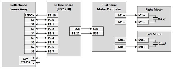
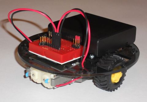
In order to follow a black line on a white surface, the Line Following Robot interfaces the NXP LPC1758 microcontroller on the SJ One Board with a Reflectance Sensor Array and Dual Serial Motor Controller. The block diagram below illustrates the connectivity of these primary components. The diagram also illustrates the connectivity between the Dual Serial Motor Controller, two brushed DC motors, twin motor gearbox, and two tires.
The LPC1758 microcontroller acquires sensor data from the Reflectance Sensor Array, generates motor commands to steer the Line Following Robot based on the sensor data, and transmits the motor commands via a serial communication interface to the Dual Serial Motor Controller. Upon receipt of the motor commands, the Dual Serial Motor Controller provides the appropriate PWM control signals to the brushed DC motors to steer the Line Following Robot. The process of obtaining sensor data from the Reflectance Sensor Array and transmitting the corresponding motor commands to the Dual Serial Motor Controller repeats at a 20 Hz rate.
Reflectance Sensor Array
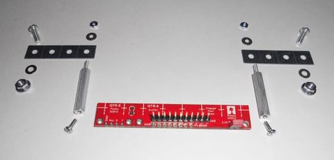
The Reflectance Sensor Array includes eight sensors. Each of the eight sensors consists of an IR LED, a phototransistor, and a capacitor connected in series with the phototransistor. To obtain a reflectivity reading from the Reflectance Sensor Array, the microcontroller GPIO pins connected to the sensor I/O pins are driven high to charge the capacitors. Once the capacitors have been fully charged, the microcontroller switches its GPIO pins to inputs. With the microcontroller GPIO pins switched to inputs, the capacitors begin discharging through the phototransistors at a rate based on the reflectivity of the surface illuminated by the IR LEDs. After allowing an appropriate amount of time for the capacitors to discharge accordingly, the eight sensor I/O pins of the Reflectance Sensor Array are read by the microcontroller.
A white surface has a high reflectivity and will turn the phototransistor on. When the phototransistor is turned on, the capacitor in series with it will be allowed to discharge through the phototransistor. With the capacitor discharged, a low voltage will be present at the sensor I/O pin and will be converted as a logical zero by the microcontroller. In contrast, a black surface has a low reflectivity and will not turn the phototransistor on. When the phototransistor is off, the capacitor in series with it will not be allowed to discharge through the phototransistor. As a result, a high voltage will be present at the sensor I/O pin and will be converted as a logical high by the microcontroller. Thus, sensors detecting a white surface will return a logical zero and sensors detecting a black surface will return a logical one when the microcontroller reads the Reflectance Sensor Array.
Sensor Data Analysis
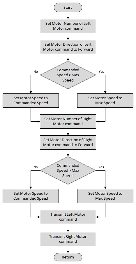
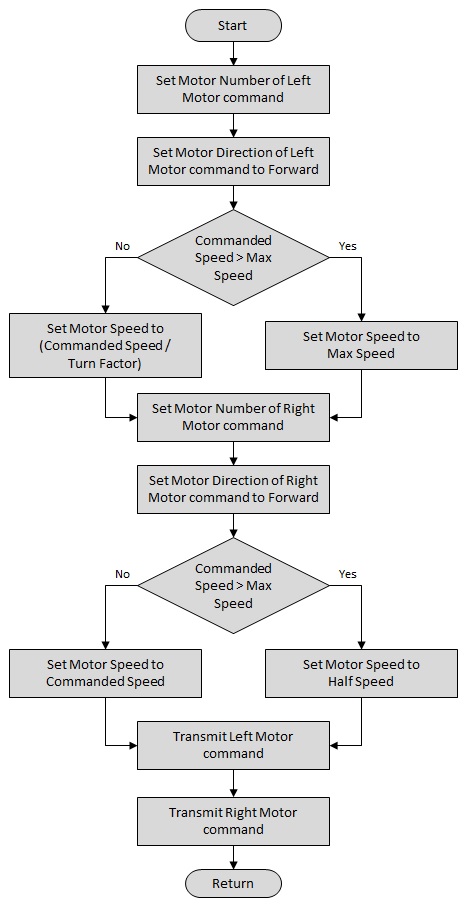
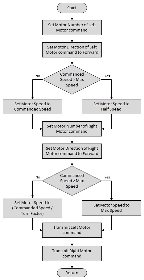
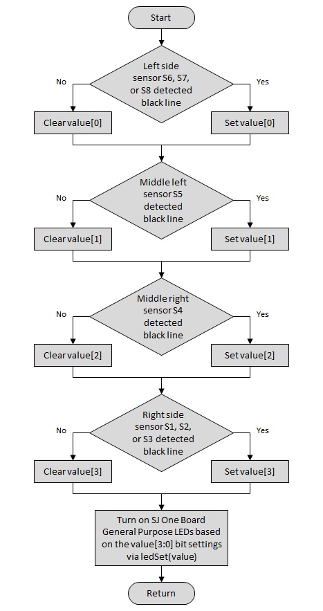
After obtaining a reflectivity reading from the Reflectance Sensor Array, the microcontroller analyzes the data to determine the appropriate motor command to be sent to the Dual Serial Motor Controller. If none of the eight sensors detect a black line, a move forward command is sent to the Dual Serial Motor Controller to continue searching for a black line to follow. A move forward command is also sent to the Dual Serial Motor Controller if either of the two or both of the middle sensors detects a black line. When any of the three sensors on the left side of the Reflectance Sensor Array detect a black line, the Dual Serial Motor Controller is commanded to turn left towards the line. Similarly, if any of the three sensors on the right side of the array detects a black line, a turn right command is sent to the Dual Serial Motor Controller.
Dual Serial Motor Controller
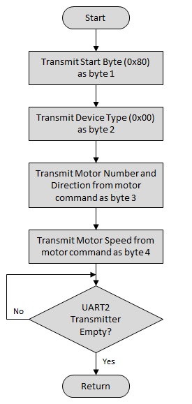
The Dual Serial Motor Controller accepts commands via its serial communication interface using a baud rate between 1200 and 19200 with eight data bits, no parity bit, and one stop bit. Its serial interface is receive-only and automatically detects the baud rate. The UART2 peripheral of the microcontroller is configured to transmit the generated motor commands to the Dual Serial Motor Controller at a baud rate of 9600.
Upon receipt of a motor command, the Dual Serial Motor Controller adjusts its PWM motor control outputs to perform the commanded action. The PWM motor control outputs operate at a frequency of 600 Hz and the voltage level is based on the input motor voltage supplied to the Dual Serial Motor Controller. The PWM motor control outputs provide independent control of two brushed DC motors. The independent control of the two motors allows the Line Following Robot to turn left or right using a ball caster as the third point of balance.
Power
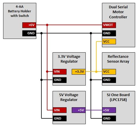
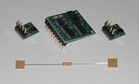
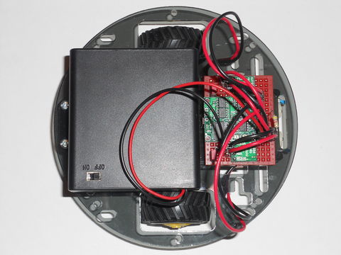
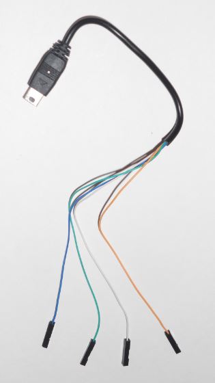
Power for the Line Following Robot is provided by four AA batteries contained in an enclosed battery holder with an included power switch. The four AA batteries generate 6.0 volts which is routed as the motor input voltage to the Dual Serial Motor Controller, the input voltage to the 5.0 V Step-Down Voltage Regulator, and the input voltage to the 3.3 V Step-Down Voltage Regulator. The regulated 5.0 volts is routed to the SJ One Board via a modified USB Mini-B cable. The SJ One Board further regulates the 5.0 volts to 3.3 volts for use by the LPC1758 microcontroller and the other components on the board. The 3.3 V Step-Down Voltage Regulator output is routed to both the Reflectance Sensor Array and the Dual Serial Motor Controller.
Team Members & Responsibilities
- Kurt Breault II
- Hardware Design
- Driver Development
- Software Design
- Integration and Test
- Project Documentation
Schedule
The proposed schedule lists the tasks to be completed each week. The time frame for each task spans from a Wednesday to the following Tuesday. This time frame format was selected to facilitate project progress discussions with the professor at the end of each weekly lecture held on Tuesday.
| Week | Date | Proposed Schedule | Actual Schedule |
|---|---|---|---|
| 1 | 10/02 to 10/08 | Write project proposal. Begin ordering components. |
|
| 2 | 10/09 to 10/15 | Finish ordering components. |
|
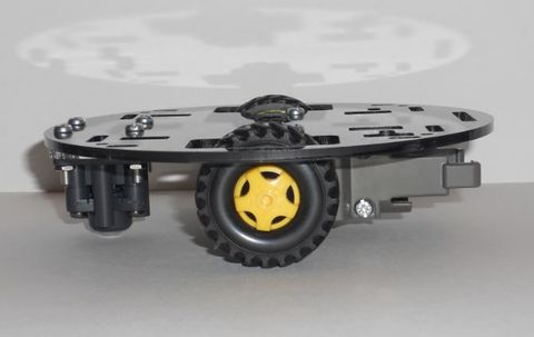
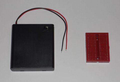
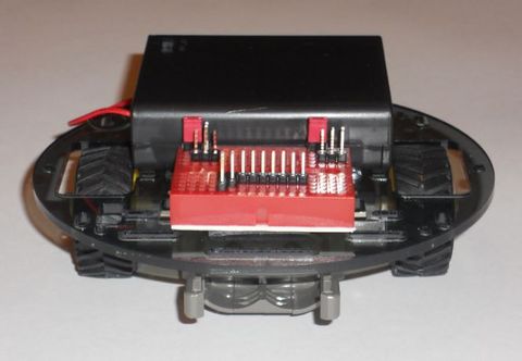
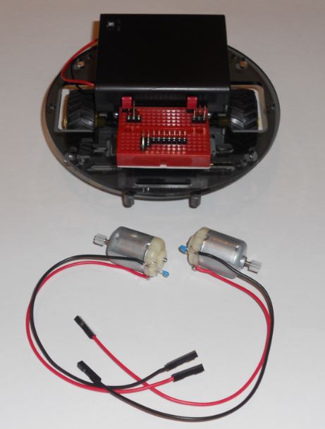
| 3 | 10/16 to 10/22 | Generate proposed schedule. Begin mechanical layout of components. Begin electrical layout of componets. |
|
| 4 | 10/23 to 10/29 | Complete mechanical layout of components. Complete electrical layout of components. |
|
| 5 | 10/30 to 11/05 | Interface SJ One Board with IR LED Reflectance Sensor Array. |
|
| 6 | 11/06 to 11/12 | Interface SJ One Board with Dual Serial Motor Controller. |
|
| 7 | 11/13 to 11/19 | Begin integration and test of SJ One Board, IR LED Reflectance Sensor Array, and Dual Serial Motor Controller. |
|
| 8 | 11/20 to 11/26 | Complete integration and test of SJ One Board, IR LED Reflectance Sensor Array, and Dual Serial Motor Controller. |
|
| 9 | 11/27 to 12/03 | Demonstrate project. Write project report. |
|
| 10 | 12/04 to 12/07 | Complete project report. |
|
Parts List & Cost
The table below summarizes the parts used and the cost for the Line Following Robot project.
| Qty | Item Description | Manufacturer | Manufacturer Item No. | Vendor | Vendor Item No. | Cost | Total Cost |
|---|---|---|---|---|---|---|---|
| 1 | SJ One Board (LPC1758) | SJSU | N/A | SJSU | N/A | $75.00 | $75.00 |
| 1 | QTR-8RC Reflectance Sensor Array | Pololu | 961 | Pololu | 961 | $9.95 | $9.95 |
| 1 | Pololu Low-Voltage Dual Serial Motor Controller | Pololu | 120 | Pololu | 120 | $39.95 | $39.95 |
| 1 | Pololu 3.3V, 600mA Step-Down Voltage Regulator D24V6F3 | Pololu | 2106 | Pololu | 2106 | $5.95 | $5.95 |
| 1 | Pololu 5V, 600mA Step-Down Voltage Regulator D24V6F5 | Pololu | 2107 | Pololu | 2107 | $5.95 | $5.95 |
| 2 | Pololu Robot Chassis RRC01A Transparent Gray | Pololu | 250 | Pololu | 250 | $5.95 | $11.90 |
| 1 | Tamiya 70097 Twin-Motor Gearbox Kit | Tamiya | 70097 | Pololu | 61 | $12.00 | $12.00 |
| 1 | Tamiya 70144 Ball Caster Kit (2 casters) | Tamiya | 70144 | Pololu | 66 | $5.99 | $5.99 |
| 1 | Tamiya 70101 Truck Tire Set (4 tires) | Tamiya | 70101 | Pololu | 65 | $4.80 | $4.80 |
| 1 | 4-AA Battery Holder, Enclosed with Switch | N/A | N/A | Pololu | 1159 | $1.75 | $1.75 |
| 4 | AA Alkaline Battery | Panasonic - BSG | LR6XWA/B | Digi-Key | P646-ND | $0.35 | $1.40 |
| 1 | 170-Point Breadboard (Red) | N/A | N/A | Pololu | 1491 | $2.95 | $2.95 |
| 1 | USB Cable A to Mini-B, 6 ft | N/A | N/A | Pololu | 130 | $2.49 | $2.49 |
| 1 | 0.100" (2.54 mm) Breakaway Male Header: 1x40-Pin, Straight, Double-Sided | N/A | N/A | Pololu | 1065 | $1.49 | $1.49 |
| 3 | 0.100" (2.54 mm) Shorting Block: Red, Top Closed | N/A | N/A | Pololu | 971 | $0.19 | $0.57 |
| 1 | Ceramic Capacitor 6-Pack 0.1uF 50V | N/A | N/A | Pololu | 1165 | $0.99 | $0.99 |
| 1 | Stranded Wire: Black, 22 AWG, 50 Feet | N/A | N/A | Pololu | 2640 | $5.00 | $5.00 |
| 1 | Stranded Wire: Red, 22 AWG, 50 Feet | N/A | N/A | Pololu | 2642 | $5.00 | $5.00 |
| 1 | Stranded Wire: White, 22 AWG, 50 Feet | N/A | N/A | Pololu | 2649 | $5.00 | $5.00 |
| 1 | Female Crimp Pins for 0.1" Housings 100-Pack | N/A | N/A | Pololu | 1930 | $5.95 | $5.95 |
| 2 | 0.1" (2.54mm) Crimp Connector Housing: 1x1-Pin 25-Pack | N/A | N/A | Pololu | 1900 | $0.59 | $1.18 |
| 1 | Resistor Kit - 1/4W (500 total) | N/A | N/A | SparkFun | COM-10969 | $7.95 | $7.95 |
| 1 | 0.100" (2.54 mm) Breakaway Male Header: 1x40-Pin, Straight | N/A | N/A | Pololu | 965 | $0.99 | $0.99 |
| 1 | Aluminum Standoff: 1" Length, 2-56 Thread, M-F (4-Pack) | N/A | N/A | Pololu | 1944 | $1.59 | $1.59 |
| 1 | Machine Screw: #2-56, 1/4" Length, Phillips (25-pack) | N/A | N/A | Pololu | 1955 | $0.59 | $0.59 |
| 1 | Machine Hex Nut: #2-56 (25-pack) | N/A | N/A | Pololu | 1067 | $0.99 | $0.99 |
| 1 | Machine Washer: #2 (100-pack) | B&F Fastener Supply | FWSS 002 | Digi-Key | H733-ND | $3.36 | $3.36 |
| 1 | Machine Washer: #4 (100-pack) | B&F Fastener Supply | FWSS 004 | Digi-Key | H734-ND | $3.48 | $3.48 |
| 1 | Tamiya 70164 Universal Metal Joint Parts (4pcs) | Tamiya | 70164 | Pololu | 90 | $3.90 | $3.90 |
| 1 | Aluminum Standoff: 1-1/4" Length, 4-40 Thread, M-F (4-Pack) | N/A | N/A | Pololu | 1951 | $1.99 | $1.99 |
| 1 | Aluminum Standoff: 3/4" Length, 4-40 Thread, M-F (4-Pack) | N/A | N/A | Pololu | 1949 | $1.59 | $1.59 |
| 1 | Machine Hex Nut: #4-40 (25-pack) | N/A | N/A | Pololu | 1068 | $0.99 | $0.99 |
| 1 | Machine Screw: #4-40, 5/16" Length, Phillips (25-pack) | N/A | N/A | Pololu | 1961 | $0.69 | $0.69 |
| 4 | Aluminum Standoff: 3/8" Length, 6-32 Thread, F-F | Keystone Electronics | 2209 | Digi-Key | 2209K-ND | $0.40 | $1.60 |
| 1 | Machine Washer: #6 (100-pack) | B&F Fastener Supply | FWSS 006 | Digi-Key | H735-ND | $3.66 | $3.66 |
| 1 | Machine Screw: #6-32, 1/4" Length, Phillips (100-pack) | B&F Fastener Supply | PMSSS 632 0025 PH | Digi-Key | H708-ND | $6.54 | $6.54 |
| 1 | Machine Screw: #6-32, 3/8" Length, Phillips (100-pack) | B&F Fastener Supply | PMSSS 632 0038 PH | Digi-Key | H710-ND | $8.10 | $8.10 |
| 1 | Scotch Removable Mounting Squares, 1" x 1", 16 ct. | Scotch | N/A | Amazon | N/A | $7.99 | $7.99 |
| 1 | Crimping Tool: 0.1-1.0 mm² Capacity, 16-28 AWG | N/A | N/A | Pololu | 1928 | $34.95 | $34.95 |
| 1 | ST-1 Mini Diagonal Cutter | N/A | N/A | Pololu | 159 | $3.99 | $3.99 |
| 1 | ST-2 Mini Long-Nose Pliers | N/A | N/A | Pololu | 150 | $3.99 | $3.99 |
| 1 | Paladin Tools 1118 GripP 20 Wire Stripper/Cutter, 30-20 AWG | Greenlee Communications | PA1118 | Digi-Key | PA1118-ND | $17.33 | $17.33 |
| Total Cost | $321.52 |
Design & Implementation
The design section can go over your hardware and software design. Organize this section using sub-sections that go over your design and implementation.
Hardware Design
Discuss your hardware design here. Show detailed schematics, and the interface here.
Hardware Interface
In this section, you can describe how your hardware communicates, such as which BUSes used. You can discuss your driver implementation here, such that the Software Design section is isolated to talk about high level workings rather than inner working of your project.
Software Design
Show your software design. For example, if you are designing an MP3 Player, show the tasks that you are using, and what they are doing at a high level. Do not show the details of the code. For example, do not show exact code, but you may show psuedocode and fragments of code. Keep in mind that you are showing DESIGN of your software, not the inner workings of it.
Implementation
This section includes implementation, but again, not the details, just the high level. For example, you can list the steps it takes to communicate over a sensor, or the steps needed to write a page of memory onto SPI Flash. You can include sub-sections for each of your component implementation.
Testing & Technical Challenges
Describe the challenges of your project. What advise would you give yourself or someone else if your project can be started from scratch again? Make a smooth transition to testing section and described what it took to test your project.
Include sub-sections that list out a problem and solution, such as:
Wifi Connection Issues
Many wifi connection issues were encountered. To solve this problem, a dedicated task was created to re-connect to wifi if the connection was ever lost.
Conclusion
Conclude your project here. You can recap your testing and problems. You should address the "so what" part here to indicate what you ultimately learnt from this project. How has this project increased your knowledge?
Project Video
Upload a video of your project and post the link here.
Project Source Code
Send me your zipped source code and I will upload this to SourceForge and link it for you.
References
Acknowledgement
Any acknowledgement that you may wish to provide can be included here.
References Used
List any references used in project.
QTR-8A and QTR-8RC Reflectance Sensor Array User’s Guide
Low-voltage Dual Serial Motor Controller User’s Guide
Pololu Round Robot Chassis RRC01A User’s Guide
Video Tutorial for Crimping PCB Interconnect Cables
Appendix
You can list the references you used.

