F13: Line Following Robot
Contents
- 1 Line Following Robot
- 2 Abstract
- 3 Objectives & Introduction
- 4 Schedule
- 5 Parts List & Cost
- 6 Design & Implementation
- 7 Testing & Technical Challenges
- 8 Conclusion
- 9 References
Line Following Robot
Abstract
The Line Following Robot detects a black line on a white surface and moves forward following the line. If a black line is not detected, the Line Following Robot moves forward searching for a black line to follow. Once the Line Following Robot detects a black line, it will begin following the black line.
Objectives & Introduction
Objectives
The objectives of the Line Following Robot include:
- Move forward searching for a black line on a white surface.
- Detect a black line on a white surface.
- Generate control commands to follow a detected black line.
Introduction
In order to follow a black line on a white surface, the Line Following Robot interfaces the NXP LPC1758 microcontroller on the SJ One Board with a Reflectance Sensor Array and Dual Serial Motor Controller. The block diagram below illustrates the connectivity of these primary components. The diagram also illustrates the connectivity between the Dual Serial Motor Controller, two brushed DC motors, twin motor gearbox, and two tires.
The LPC1758 microcontroller acquires sensor data from the Reflectance Sensor Array, generates motor commands to steer the Line Following Robot based on the sensor data, and transmits the motor commands via a serial communication interface to the Dual Serial Motor Controller. Upon receipt of the motor commands, the Dual Serial Motor Controller provides the appropriate PWM control signals to the brushed DC motors to steer the Line Following Robot. The process of obtaining sensor data from the Reflectance Sensor Array and transmitting the corresponding motor commands to the Dual Serial Motor Controller repeats at a 20 Hz rate.
Reflectance Sensor Array
The Reflectance Sensor Array (RSA) includes eight sensors. Each of the eight sensors consists of an IR LED, a phototransistor, and a capacitor connected in series with the phototransistor. To obtain a reflectivity reading from the Reflectance Sensor Array, the microcontroller GPIO pins connected to the sensor I/O pins are driven high to charge the capacitors. Once the capacitors have been fully charged, the microcontroller switches its GPIO pins to inputs. With the microcontroller GPIO pins switched to inputs, the capacitors begin discharging through the phototransistors at a rate based on the reflectivity of the surface illuminated by the IR LEDs. After allowing an appropriate amount of time for the capacitors to discharge accordingly, the eight sensor I/O pins of the Reflectance Sensor Array are read by the microcontroller.
A white surface has a high reflectivity and will turn the phototransistor on. When the phototransistor is turned on, the capacitor in series with it will be allowed to discharge through the phototransistor. With the capacitor discharged, a low voltage will be present at the sensor I/O pin and will be converted as a logical zero by the microcontroller. In contrast, a black surface has a low reflectivity and will not turn the phototransistor on. When the phototransistor is off, the capacitor in series with it will not be allowed to discharge through the phototransistor. As a result, a high voltage will be present at the sensor I/O pin and will be converted as a logical high by the microcontroller. Thus, sensors detecting a white surface will return a logical zero and sensors detecting a black surface will return a logical one when the microcontroller reads the Reflectance Sensor Array.
Sensor Data Analysis
After obtaining a reflectivity reading from the Reflectance Sensor Array, the microcontroller analyzes the data to determine the appropriate motor command to be sent to the Dual Serial Motor Controller. If none of the eight sensors detect a black line, a move forward command is sent to the Dual Serial Motor Controller to continue searching for a black line to follow. A move forward command is also sent to the Dual Serial Motor Controller if either of the two or both of the middle sensors detects a black line. When any of the three sensors on the left side of the Reflectance Sensor Array detect a black line, the Dual Serial Motor Controller is commanded to turn left towards the line. Similarly, if any of the three sensors on the right side of the array detects a black line, a turn right command is sent to the Dual Serial Motor Controller.
Dual Serial Motor Controller
The Dual Serial Motor Controller (DSMC) accepts commands via its serial communication interface using a baud rate between 1200 and 19200 with eight data bits, no parity bit, and one stop bit. Its serial interface is receive-only and automatically detects the baud rate. The UART2 peripheral of the microcontroller is configured to transmit the generated motor commands to the Dual Serial Motor Controller at a baud rate of 9600.
Upon receipt of a motor command, the Dual Serial Motor Controller adjusts its PWM motor control outputs to perform the commanded action. The PWM motor control outputs operate at a frequency of 600 Hz and the voltage level is based on the input motor voltage supplied to the Dual Serial Motor Controller. The PWM motor control outputs provide independent control of two brushed DC motors. The independent control of the two motors allows the Line Following Robot to turn left or right using a ball caster as the third point of balance.
Power
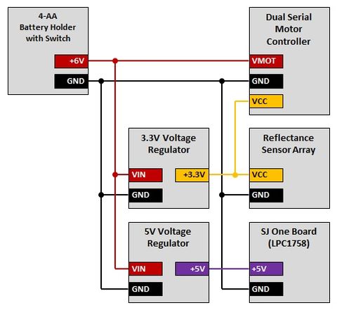
Power for the Line Following Robot is provided by four AA batteries contained in an enclosed battery holder with an included power switch. The four AA batteries generate 6.0 volts which is routed as the motor input voltage to the Dual Serial Motor Controller, the input voltage to the 5.0 V Step-Down Voltage Regulator, and the input voltage to the 3.3 V Step-Down Voltage Regulator. The regulated 5.0 volts is routed to the SJ One Board via a modified USB Mini-B cable. The SJ One Board further regulates the 5.0 volts to 3.3 volts for use by the LPC1758 microcontroller and the other components on the board. The 3.3 V Step-Down Voltage Regulator output is routed to both the Reflectance Sensor Array and the Dual Serial Motor Controller.
Team Members & Responsibilities
- Kurt Breault II
- Hardware Design
- Driver Development
- Software Design
- Integration and Test
- Project Documentation
Schedule
The proposed schedule lists the tasks to be completed each week. The time frame for each task spans from a Wednesday to the following Tuesday. This time frame format was selected to facilitate project progress discussions with the professor at the end of each weekly lecture held on Tuesday.
| Week | Date | Proposed Schedule | Actual Schedule |
|---|---|---|---|
| 1 | 10/02 to 10/08 | Write project proposal. Begin ordering components. |
|
| 2 | 10/09 to 10/15 | Finish ordering components. |
|
| 3 | 10/16 to 10/22 | Generate proposed schedule. Begin mechanical layout of components. Begin electrical layout of componets. |
|
| 4 | 10/23 to 10/29 | Complete mechanical layout of components. Complete electrical layout of components. |
|
| 5 | 10/30 to 11/05 | Interface SJ One Board with IR LED Reflectance Sensor Array. |
|
| 6 | 11/06 to 11/12 | Interface SJ One Board with Dual Serial Motor Controller. |
|
| 7 | 11/13 to 11/19 | Begin integration and test of SJ One Board, IR LED Reflectance Sensor Array, and Dual Serial Motor Controller. |
|
| 8 | 11/20 to 11/26 | Complete integration and test of SJ One Board, IR LED Reflectance Sensor Array, and Dual Serial Motor Controller. |
|
| 9 | 11/27 to 12/03 | Demonstrate project. Write project report. |
|
| 10 | 12/04 to 12/07 | Complete project report. |
|
Parts List & Cost
The table below summarizes the parts used and the cost for the Line Following Robot project.
| Qty | Item Description | Manufacturer | Manufacturer Item No. | Vendor | Vendor Item No. | Cost | Total Cost |
|---|---|---|---|---|---|---|---|
| 1 | SJ One Board (LPC1758) | SJSU | N/A | SJSU | N/A | $75.00 | $75.00 |
| 1 | QTR-8RC Reflectance Sensor Array | Pololu | 961 | Pololu | 961 | $9.95 | $9.95 |
| 1 | Pololu Low-Voltage Dual Serial Motor Controller | Pololu | 120 | Pololu | 120 | $39.95 | $39.95 |
| 1 | Pololu 3.3V, 600mA Step-Down Voltage Regulator D24V6F3 | Pololu | 2106 | Pololu | 2106 | $5.95 | $5.95 |
| 1 | Pololu 5V, 600mA Step-Down Voltage Regulator D24V6F5 | Pololu | 2107 | Pololu | 2107 | $5.95 | $5.95 |
| 2 | Pololu Robot Chassis RRC01A Transparent Gray | Pololu | 250 | Pololu | 250 | $5.95 | $11.90 |
| 1 | Tamiya 70097 Twin-Motor Gearbox Kit | Tamiya | 70097 | Pololu | 61 | $12.00 | $12.00 |
| 1 | Tamiya 70144 Ball Caster Kit (2 casters) | Tamiya | 70144 | Pololu | 66 | $5.99 | $5.99 |
| 1 | Tamiya 70101 Truck Tire Set (4 tires) | Tamiya | 70101 | Pololu | 65 | $4.80 | $4.80 |
| 1 | 4-AA Battery Holder, Enclosed with Switch | N/A | N/A | Pololu | 1159 | $1.75 | $1.75 |
| 4 | AA Alkaline Battery | Panasonic - BSG | LR6XWA/B | Digi-Key | P646-ND | $0.35 | $1.40 |
| 1 | 170-Point Breadboard (Red) | N/A | N/A | Pololu | 1491 | $2.95 | $2.95 |
| 1 | USB Cable A to Mini-B, 6 ft | N/A | N/A | Pololu | 130 | $2.49 | $2.49 |
| 1 | 0.100" (2.54 mm) Breakaway Male Header: 1x40-Pin, Straight, Double-Sided | N/A | N/A | Pololu | 1065 | $1.49 | $1.49 |
| 3 | 0.100" (2.54 mm) Shorting Block: Red, Top Closed | N/A | N/A | Pololu | 971 | $0.19 | $0.57 |
| 1 | Ceramic Capacitor 6-Pack 0.1uF 50V | N/A | N/A | Pololu | 1165 | $0.99 | $0.99 |
| 1 | Stranded Wire: Black, 22 AWG, 50 Feet | N/A | N/A | Pololu | 2640 | $5.00 | $5.00 |
| 1 | Stranded Wire: Red, 22 AWG, 50 Feet | N/A | N/A | Pololu | 2642 | $5.00 | $5.00 |
| 1 | Stranded Wire: White, 22 AWG, 50 Feet | N/A | N/A | Pololu | 2649 | $5.00 | $5.00 |
| 1 | Female Crimp Pins for 0.1" Housings 100-Pack | N/A | N/A | Pololu | 1930 | $5.95 | $5.95 |
| 2 | 0.1" (2.54mm) Crimp Connector Housing: 1x1-Pin 25-Pack | N/A | N/A | Pololu | 1900 | $0.59 | $1.18 |
| 1 | Resistor Kit - 1/4W (500 total) | N/A | N/A | SparkFun | COM-10969 | $7.95 | $7.95 |
| 1 | 0.100" (2.54 mm) Breakaway Male Header: 1x40-Pin, Straight | N/A | N/A | Pololu | 965 | $0.99 | $0.99 |
| 1 | Aluminum Standoff: 1" Length, 2-56 Thread, M-F (4-Pack) | N/A | N/A | Pololu | 1944 | $1.59 | $1.59 |
| 1 | Machine Screw: #2-56, 1/4" Length, Phillips (25-pack) | N/A | N/A | Pololu | 1955 | $0.59 | $0.59 |
| 1 | Machine Hex Nut: #2-56 (25-pack) | N/A | N/A | Pololu | 1067 | $0.99 | $0.99 |
| 1 | Machine Washer: #2 (100-pack) | B&F Fastener Supply | FWSS 002 | Digi-Key | H733-ND | $3.36 | $3.36 |
| 1 | Machine Washer: #4 (100-pack) | B&F Fastener Supply | FWSS 004 | Digi-Key | H734-ND | $3.48 | $3.48 |
| 1 | Tamiya 70164 Universal Metal Joint Parts (4pcs) | Tamiya | 70164 | Pololu | 90 | $3.90 | $3.90 |
| 1 | Aluminum Standoff: 1-1/4" Length, 4-40 Thread, M-F (4-Pack) | N/A | N/A | Pololu | 1951 | $1.99 | $1.99 |
| 1 | Aluminum Standoff: 3/4" Length, 4-40 Thread, M-F (4-Pack) | N/A | N/A | Pololu | 1949 | $1.59 | $1.59 |
| 1 | Machine Hex Nut: #4-40 (25-pack) | N/A | N/A | Pololu | 1068 | $0.99 | $0.99 |
| 1 | Machine Screw: #4-40, 5/16" Length, Phillips (25-pack) | N/A | N/A | Pololu | 1961 | $0.69 | $0.69 |
| 4 | Aluminum Standoff: 3/8" Length, 6-32 Thread, F-F | Keystone Electronics | 2209 | Digi-Key | 2209K-ND | $0.40 | $1.60 |
| 1 | Machine Washer: #6 (100-pack) | B&F Fastener Supply | FWSS 006 | Digi-Key | H735-ND | $3.66 | $3.66 |
| 1 | Machine Screw: #6-32, 1/4" Length, Phillips (100-pack) | B&F Fastener Supply | PMSSS 632 0025 PH | Digi-Key | H708-ND | $6.54 | $6.54 |
| 1 | Machine Screw: #6-32, 3/8" Length, Phillips (100-pack) | B&F Fastener Supply | PMSSS 632 0038 PH | Digi-Key | H710-ND | $8.10 | $8.10 |
| 1 | Scotch Removable Mounting Squares, 1" x 1", 16 ct. | Scotch | N/A | Amazon | N/A | $7.99 | $7.99 |
| 1 | Crimping Tool: 0.1-1.0 mm² Capacity, 16-28 AWG | N/A | N/A | Pololu | 1928 | $34.95 | $34.95 |
| 1 | ST-1 Mini Diagonal Cutter | N/A | N/A | Pololu | 159 | $3.99 | $3.99 |
| 1 | ST-2 Mini Long-Nose Pliers | N/A | N/A | Pololu | 150 | $3.99 | $3.99 |
| 1 | Paladin Tools 1118 GripP 20 Wire Stripper/Cutter, 30-20 AWG | Greenlee Communications | PA1118 | Digi-Key | PA1118-ND | $17.33 | $17.33 |
| Total Cost | $321.52 |
Design & Implementation
Hardware Design
The hardware design of the Line Following Robot is separately described in terms of routing power and signals. The routing of power and signals is considered separately to simplify their description and associated diagrams.
Power Routing
Power for the Line Following Robot is provided by four AA batteries. The four AA batteries are installed in an enclosed battery holder that includes a power switch. The power switch on the enclosed battery holder is used to power the Line Following Robot on and off. When the power switch is set to the on position, the four AA batteries provide +6.0 V.
The +6.0 V provided by the four AA batteries is routed to the VMOT input of the Dual Serial Motor Controller. The VMOT input of the Dual Serial Motor Controller provides the raw motor voltage used to control the brushed DC motors via its PWM motor control outputs. The +6.0 V provided by the four AA batteries is also routed to the VIN inputs of the 3.3V Step-Down Voltage Regulator and 5V Step-Down Voltage Regulator. These connections and the other power routing connections of the Line Following Robot are illustrated in the figure below.
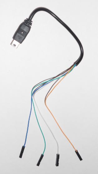
The 3.3V output of the 3.3V Step-Down Voltage Regulator is routed to VCC inputs of the Reflectance Sensor Array and the Dual Serial Motor Controller to provide the logic voltage for these devices. The 5V output of the 5V Step-Down Voltage Regulator is routed to the +5V input of the USB Mini-B connector on the SJ One Board via a modified USB Mini-B Cable. The SJ One Board routes the 5V input voltage to its own internal voltage regulator to supply 3.3V to the on-board LPC1758 microcontroller and other on-board devices. Although the SJ One Board provides its internally generated 3.3V as an output for peripherals, the SJ One Board 3.3V output could not be used due to the current draw on the 5V Step-Down Voltage Regulator and its associated dropout voltage.
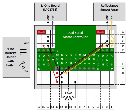
The distribution of power for the Line Following Robot is accomplished via the breadboard power routing connections illustrated in the figure below. In addition to the previously described routing of power, both the 3.3V Step-Down Voltage Regulator and 5V Step-Down Voltage Regulator require their active-low SHDN inputs to be tied to their 3.3V and 5V outputs, respectively. These connections are made on the 170-point breadboard via shorting blocks, a.k.a. jumpers, as depicted by the red rectangles in the breadboard power routing connections diagram.
The 1.0 kOhm pull-down resistor for the active-low RST input of the Dual Serial Motor Controller is also illustrated in the breadboard power routing connections diagram. The pull-down resistor is required in the event the microcontroller itself is reset. When the microcontroller is reset, its pins are switched to inputs and no longer provide the intended control for the Dual Serial Motor Controller. The pull-down resistor overrides the floating input condition and asserts reset to the Dual Serial Motor Controller to ensure the motors do not keep running while the microcontroller is recovering from reset.
Finally, the breadboard power routing connections diagram provides the installation location of the Dual Serial Motor Controller, 3.3V Step-Down Voltage Regulator, and 5V Step-Down Voltage Regulator on the 170-point breadboard. Straight male header connectors of the appropriate length are soldered onto each of these components and used to install them on the breadboard. The three components have been drawn to scale relative to the breadboard to provide an indication of the area they consume.
Signal Routing
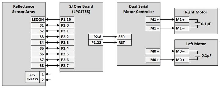
The Spare I/O pins of the SJ One Board are used to interface the LPC1758 microcontroller with the Reflectance Sensor Array and the Dual Serial Motor Controller. As shown in the figure below, pin P1.19 is configured as a GPIO output connected to the LEDON input of the Reflectance Sensor Array. The LEDON signal is used to turn on the eight IR LEDs while performing a reflectivity reading and to turn them off after obtaining the reading. Turning the IR LEDs off between reflectivity readings conserves power when they are not in use. The P2.0 through P2.7 pins are used as GPIO inputs and outputs. These pins are routed to the eight sensor ports of the Reflectance Sensor Array. When configured as an output, they are driven high to charge the capacitors associated with each of the eight IR LED and phototransistor pairs. When configured as an input, they are read to obtain the reflectivity reading based on the surface illuminated by the IR LEDs.
The remaining connection for the Reflectance Sensor Array does not involve the LPC1758 microcontroller. In order to operate the Reflectance Sensor Array using a 3.3V logic voltage, the two 3.3V bypass pins are connected together using a jumper installed across the male header pins. This connection is required to bypass the second stage of current limiting resistors required to operate the IR LEDs when Reflectance Sensor Array is interfaced with components operating at a 5V logic voltage. With the second stage of current limiting resistors bypassed for 3.3V operation, a sufficient amount of current flows through the IR LEDs to turn them on when the LEDON input is driven high.
The SER input of the Dual Serial Motor Controller is connected to pin P2.8. Pin P2.8 is configured as the TXD2 output of the LPC1758 UART2 peripheral and is used to transmit the motor commands. The RST input of the Dual Serial Motor Controller is connected to pin P1.22. Pin P1.22 is configured as a GPIO output to provide the active-low reset for the Dual Serial Motor Controller during initialization of the Line Following Robot.
Other Dual Serial Motor Controller connections depicted by the signal routing diagram include the PWM motor control voltages. The M0+ and M0- outputs are routed to the left motor and the M1+ and M1- outputs are routed to the right motor. As suggested by the Dual Serial Motor Controller User Guide, a 0.1 uF capacitor has been soldered across the two input leads of both motors to reduce the amount of electrical noise generated by the brushed DC motors.
Hardware Interface
The hardware interface is described in terms of the drivers developed for the Line Following Robot. Drivers were required to interface with the Reflectance Sensor Array, Dual Serial Motor Controller, and SJ One Board General Purpose LEDs. The following subsections provide details and flow diagrams for the driver functions developed to interface with these components.
Reflectance Sensor Array Interface
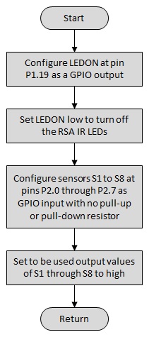
The Reflectance Sensor Array interface requires two driver functions. These functions include initialization and reading the sensor. The initialization function configures the microcontroller pins selected for the LEDON input and eight sensor inputs/outputs of the Reflectance Sensor Array. Microcontroller pin P1.19 is routed as LEDON and pins P2.0 through P2.7 are routed as the eight sensor inputs/outputs. The LEDON pin is configured as a GPIO output driving low to turn off the IR LEDs following power-up and reset. The eight sensor inputs/outputs are configured as GPIO inputs with no pull-up or pull-down resistor. The GPIO output values, to be used when a sensor reflectivity reading is performed, are set to high. The flow diagram below illustrates the steps of the Reflectance Sensor Array initialization function.
The read function performs the steps provided in the user’s guide for the Reflectance Sensor Array to obtain a sensor reflectivity reading. The GPIO output connected to LEDON is driven high to turn on the IR LEDs and begin illuminating the surface under the sensors. The eight sensor GPIO pins are set to output driving high to charge the capacitor located in series with the phototransistor of each sensor. The capacitors are charge after a delay of 100 us and the eight sensor GPIO pins are then switched to input to allow the capacitors to discharge through its in series phototransistor based on the reflectivity of the surface illuminated by IR LEDs. Following a delay of 700 us, the GPIO pins are read to obtain the sensor reflectivity reading. Finally, the IR LEDs are turned off by driving the LEDON output low and the sensor reflectivity reading is returned. The flow diagram below illustrates the steps of the Reflectance Sensor Array read function.
Dual Serial Motor Controller Interface
The Dual Serial Motor Controller interface requires driver functions to perform initialization, transmit motor commands, and provide coordinated movement. It receives four-byte motor commands via a serial communication interface using a baud rate between 1200 and 19200, eight data bits, no parity bit, and one stop bit. The baud rate is automatically detected upon the receipt of the first command following power-up or reset. The serial communication interface of the Dual Serial Motor Controller is receive-only and does not provide any feedback.
The initialization function configures the microcontroller pins selected for the RST input and the SER input of the Dual Serial Motor Controller. Microcontroller pins P1.22 and P2.8 are routed as RST and SER, respectively. The RST pin (pin P1.22) is configured as a GPIO output with an initial value of low to assert the active-low reset of the Dual Serial Motor Controller following power-up and reset. The SER pin (pin P2.8) is configured as TXD2 of the microcontroller UART2 peripheral. The UART2 peripheral is configured to use a baud rate of 9600, eight data bits, no parity bit, and one stop bit. The active-low reset of the Dual Serial Motor Controller is released following a 20 us delay to ensure its required minimum reset assertion time has been met. After the reset has been released and prior to the return from the initialization function, a delay of 200 us transpires to ensure the minimum reset recovery time is met for the Dual Serial Motor Controller. The flow diagram below illustrates the steps of the Dual Serial Motor Controller initialization function.
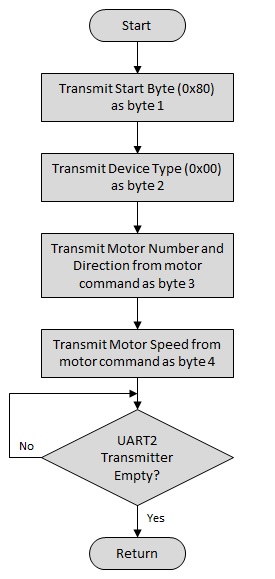
A motor command for the Dual Serial Motor Controller consists of four bytes. The first byte contains the Start Byte to indicate beginning of a motor command and must be equal to 0x80. The second byte contains the Device Type and must be set equal to 0x00 for the Dual Serial Motor Controller. The third byte specifies the motor number and direction. The motor number selects which of the two motors are being commanded and the direction specifies either forward or reverse. The fourth and final byte of the motor command contains the speed setting for the motor commanded in the third byte.
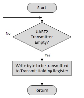
In order to transfer the generated motor commands from the microcontroller to the Dual Serial Motor Controller, driver functions to transmit a single byte and to transmit a full motor command have been developed. The transmit byte function is equivalent to the simple UART transmit function. This function waits for the UART2 transmitter FIFOs to be empty. Once the UART2 transmit FIFOs indicate an empty condition, the byte to be transmitted is written to the UART2 transmit holding register. The flow diagram for the Dual Serial Motor Controller transmit byte function is provided below.
The transmit command function simply calls the transmit byte function for each of the four bytes of the input motor command. After the transmit byte function call for the last byte of the motor command, the function waits for the UART2 transmit FIFOs to be empty. Waiting for the UART2 transmit FIFOs to be empty ensures the full motor command has been transmitted before returning from the function call. The flow diagram for the Dual Serial Motor Controller transmit command function is provided below.
The movement functions for the Dual Serial Motor Controller make use of the transmit command function to independently direct the left and right motors according to the desired action. The movement functions include stop, move forward, turn forward left, and turn forward right. The Dual Serial Motor Controller User’s Guide suggests a broadcast motor number can be used to send a single command to both motors using the same direction and speed. Since the stop and move forward commands require both motors to perform the same action, they were originally designed to use the broadcast motor number. Unfortunately, the broadcast motor number feature did not function as described in the user’s guide. As a result, separate motor commands for the left and right motors are constructed and transmitted for the stop and move forward movement functions. The details for the four movement functions are described below with their associated flow diagrams.
The stop function constructs separate left and right motor commands and then transmits them to the Dual Serial Motor Controller. The motor number for the left and right motor commands is set based on the assigned left and right motor numbers. The direction is set to forward and the speed is set to zero in both motor commands. The flow diagram for the Dual Serial Motor Controller stop function is provided below.
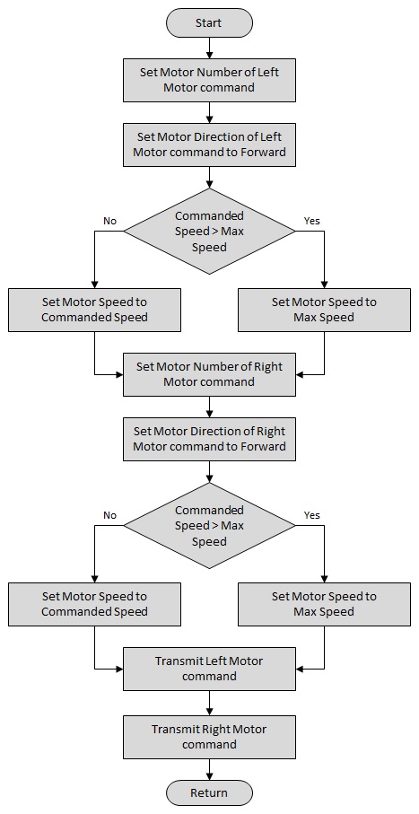
The move forward function constructs separate left and right motor commands before transmitting them to the Dual Serial Motor Controller. The motor number for the left and right motor commands is set based on the assigned left and right motor numbers. The direction is set to forward and the speed is set to specified input speed in both motor commands. Prior to setting the commanded motor speed, a check is performed to limit the specified input speed to the maximum allowable speed setting. The flow diagram for the Dual Serial Motor Controller move forward function is provided below.
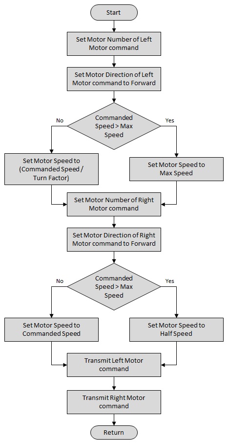
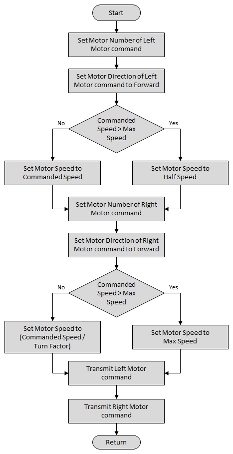
The turn forward left function constructs separate left and right motor commands before transmitting them to the Dual Serial Motor Controller. The motor number for the left and right motor commands is set based on the assigned left and right motor numbers. The direction is set to forward in both motor commands. In order to perform a forward left turn, the speed of the left motor is set lower than that of the right motor. The speed of the left motor is set to the specified input speed scaled down by the turn factor and the speed of the right motor is set to the specified input speed. Prior to setting the motor speeds, a check is performed to ensure the specified input speed does not exceed the maximum allowable speed setting. If the specified input speed exceeds the maximum allowable speed setting, then the speed for the left and right motors is limited accordingly. The flow diagram for the Dual Serial Motor Controller turn forward left function is provided below.
The turn forward right function is very similar to the turn forward left function. The difference between two functions is the setting of the left and right motor speeds. The turn forward right function sets the speed of the right motor lower than that of the left motor in order to perform a forward right turn. The speed of the right motor is set to the specified input speed scaled down by the turn factor and the speed of the left motor is set to the specified input speed. As with the turn forward left function, a check is performed to ensure the specified input speed does not exceed the maximum allowable speed setting. If the specified input speed exceeds the maximum allowable speed setting, then the speed for the left and right motors is limited accordingly. The flow diagram for the Dual Serial Motor Controller turn forward right function is provided below.
SJ One Board General Purpose LED Interface
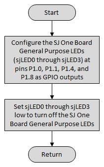
The driver functions for the SJ One Board General Purpose LED interface include initialization and setting the on/off state for each of the four LEDs. The initialization function configures the microcontroller pins connected to the SJ One Board General Purpose LEDs as GPIO outputs. These pins include P1.0, P1.1, P1.4, and P1.8 and are connected to LED0 through LED3, respectively. The GPIO outputs are driven high during initialization to turn off the LEDs. The configuration for the SJ One Board General Purpose LEDs is active-low; thus, the LEDs are turned on by setting their GPIO outputs low and turned off by setting heir GPIO outputs high. The flow diagram below illustrates the steps for the SJ One Board General Purpose LED initialization function.
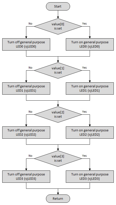
The set function controls the on/off state for each of the SJ One Board General Purpose LEDs based on the specified input value. The lower four bits of the input value correspond to the four LEDs such that bit 0 of value maps to LED0, bit 1 of value maps to LED1, etc. If a bit in value mapped to an LED is set, the corresponding LED is turned on. If the bit in value is not set, the corresponding LED is turned off. The flow diagram below illustrates the steps of the SJ One Board General Purpose LED set function.
Mechanical Design
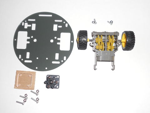
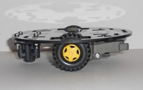
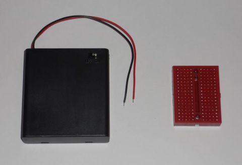
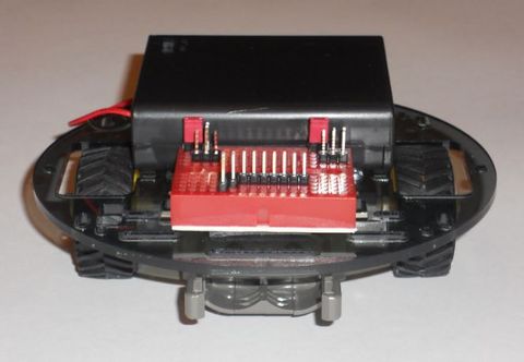
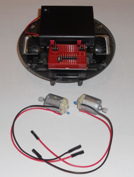
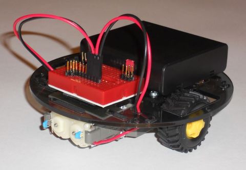
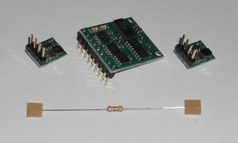
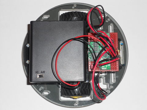
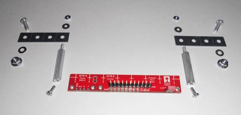
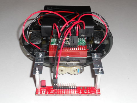
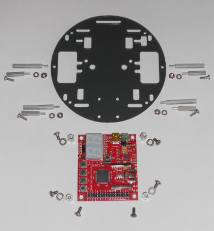
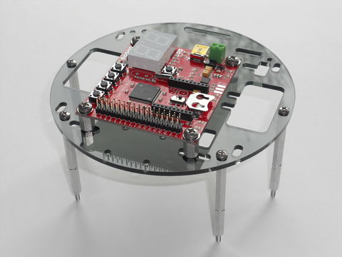
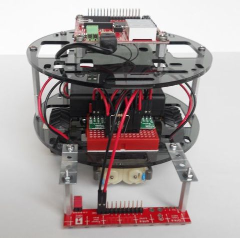
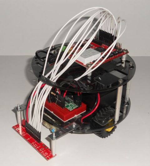
The mechanical design of the Line Following Robot is documented using a series of photographs taken during its construction. These photographs are intended to guide others through the assembly of the Line Following Robot. Since no assembly instructions were available during the original construction of the Line Following Robot, a considerable amount of time and effort was spent on its mechanical design. It is hoped these step-by-step photographs will alleviate this effort in future projects so that more focus can be applied toward the hardware and software design. With the time saved on the mechanical design, more time can be spent enhancing the line following algorithm and/or providing additional features for the Line Following Robot, such as starting and stopping the robot via the IR sensor installed on the SJ One Board or adding proximity sensors for collision avoidance.
Software Design
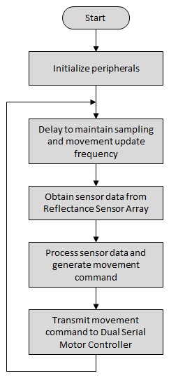
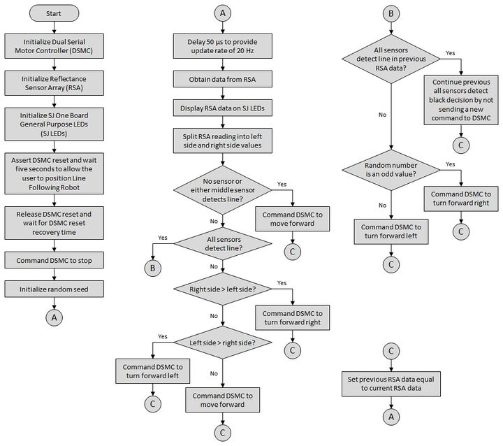
The overall software design for the Line Following Robot is relatively simple because most of the work is performed by the drivers described in the hardware interface. Program execution begins by initializing the peripherals of the Line Following Robot. After the peripherals are initialized, program execution enters a continuous loop designed to search for and follow a black line on a white surface. This loop is repeated at a fixed interval to provide consistent motion of the Line Following Robot. The loop begins by reading the Reflectance Sensor Array to obtain sensor data. The sensor data is then processed to determine the appropriate movement command required to search for or follow a black line. Finally, the selected movement command is transmitted to the Dual Serial Motor Controller to perform the commanded movement. The flow diagram below illustrates the steps required in the software design for the Line Following Robot.
Implementation
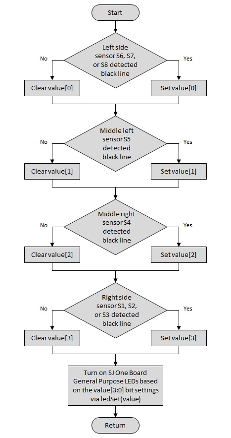
The implementation of the Line Following Robot is straightforward due to the amount of detailed work performed by the drivers described in the hardware interface. As a result, only one utility function was required to supplement the main routine. This utility function displays the Reflectance Sensor Array data reading on the SJ One Board General Purpose LEDs to provide visual feedback of the data read from the sensor array to the user. The display Reflectance Sensor Array data function turns on SJ LED0 if any of the three left-most sensors detect a black surface. SJ LED0 is turned off if a black surface is not detected by any one of the three left-most sensors. Similarly, SJ LED1 and SJ LED2 are turned on or off based on the detection of a black sensor by the single middle left and single middle right sensors, respectively. Finally, SJ LED3 is turned on or off based on the surface detected by the three right-most sensors. The flow diagram below provides the steps required to control the SJ One Board General Purpose LEDs based on the Reflectance Sensor Array data reading.
The flow diagram below and the following subsections detail the overall flow and steps performed by the software implementation of the Line Following Robot.
Initialization
The main routine for the Line Following Robot begins by initializing the Dual Serial Motor Controller, Reflectance Sensor Array, and the SJ One Board General Purpose LEDs. Following the initialization of these peripherals, the Dual Serial Motor Controller is held in reset for five seconds to allow the user to position the Line Following Robot on a line following course. An opportunity for a future enhancement would include using the general purpose switches on the SJ One Board to start and stop the Line Following Robot. Alternatively, the infrared receiver on the SJ One Board could be used to receive start and stop commands from a simple infrared remote control.
Upon release of the Dual Serial Motor Controller reset, a stop command is transmitted to the Dual Serial Motor Controller so it can detect the baud rate used for transferring motor commands. The final step of initialization is to seed the random number generator. The use of random numbers is explained later in the processing of sensor data description. With the initialization steps completed, program execution enters the main processing loop for the Line Following Robot.
Obtain Sensor Data
Prior to obtaining sensor data from the Reflectance Sensor Array, the main loop begins with a 50 ms delay to limit the movement command update rate to the Dual Serial Motor Controller to no more than 20 Hz. Following the delay, the Reflectance Sensor Array is read to obtain a reflectance sensor reading. The sensor reading is displayed to the SJ One Board General Purpose LEDs via the display Reflectance Sensor Data function described above and then used to calculate left side and right side values. The left side and right side sensor values are used during the processing of sensor data to help determine the appropriate steering command. The calculation of the left side and right side sensor values is performed such that a greater weighting is applied to sensors located closer to the center of the array than those that are located near the edges of the array.
Process Sensor Data
The raw sensor data and the left and right side sensor values are processed to determine the movement command required to steer the Line Following Robot. If none of the sensors detect a black surface, the move forward command is selected to continue searching for a black line to follow. The move forward command is also selected if either of the two or both of the middle sensors detects a black surface so that the Line Following Robot continues to follow the detected black line.
When all of the sensors detect a black surface, the previous sensor data is checked to determine if all sensors detected black during the previous reading of the Reflectance Sensor Array. If the previous sensor data indicates a black surface was not detected by all of the sensors, then it is assumed a black line perpendicular to the sensor array has been encountered. In order to decide whether to turn left or to right in this case, a random number is used. If the random number is an odd value, then the turn forward right command is selected. Otherwise, the turn forward left command is selected. If the previous sensor data had indicated a black surface was already detected by all of the sensors, then no action is commanded to allow the steering of the Line Following Robot to continue with its initial turn forward left or turn forward right selection.
Other cases to consider while processing the sensor data include comparing the left and right side sensor values when none of the previously described cases is true. If the right side sensor value is greater than the left side sensor value, the turn forward right command is selected to steer the Line Following Robot towards the detected black surface. Similarly, if the left side sensor value is greater than the right side sensor value, then turn forward left command is selected. Finally, when none of these cases mentioned above are true, the move forward command is selected to ensure the Line Following Robot continues searching for or following a black line.
Transmit Motor Command
Once the selection of the movement command has been completed, the command is transferred to the Dual Serial Motor Controller in order to execute the desired steering action. The transmission of the movement command is performed by the functions provided in the Dual Serial Motor Controller drivers. After the movement command is transmit, the main loop concludes by updating the previous sensor data with the current sensor data for use in the next iteration of the loop. The main loop then returns to the aforementioned 50 ms delay prior to obtaining the next Reflectance Sensor Array data reading.
Testing & Technical Challenges
Testing
Testing of the Line Following Robot was performed at the unit level and system level. Unit level testing included the test of the Reflectance Sensor Array and Dual Serial Motor Controller drivers. Testing of the SJ One Board General Purpose LED drivers was not required because they were based on previously developed and tested code. System level testing included the integration and test of the Reflectance Sensor Array with Dual Serial Motor Controller and of the Line Following Robot itself.
RSA Unit Test
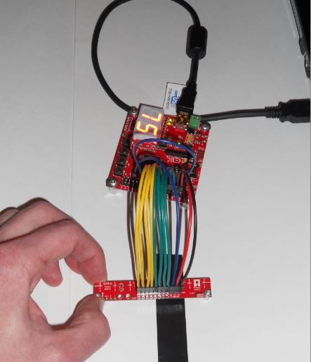
Unit test of the Reflectance Sensor Array drivers was performed by connecting the Reflectance Sensor Array to the SJ One Board and passing the sensor array over a black line on a white surface to obtain sensor readings. The sensor readings were displayed to the Hercules terminal and verified based on the positioning of the sensor array over the black line. Black electrical tape was used for the black line and white poster board was used for the white surface since these materials are used to generate line following courses. In order to ensure the distance of the Reflectance Sensor Array over the black line and white surface was consistent and equal to the distance of the sensor array when installed on the Line Following Robot, standoffs with a length of one-quarter inch were used. The photograph below depicts the setup used during unit test of the Reflectance Sensor Array.
DSMC Unit Test
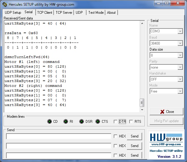
Unit test of the Dual Serial Motor Controller drivers was performed by transmitting motor commands over the UART2 TXD2 pin and looping them back to the UART3 RXD3 pin of the SJ One Board. The UART3 peripheral of the LPC1758 microcontroller was configured to use the same serial communication interface settings used by the Dual Serial Motor Controller. The UART3 peripheral was selected to support debug and test because it is unused by the Line Following Robot. The motor commands transmitted over the UART2 TXD2 pin and received by the UART3 RXD3 pin were read from the UART3 receive FIFO and displayed to the Hercules terminal to verify the validity of the interface settings and contents of the motor commands.
RSA and DSMC System Test
System test of the Reflectance Sensor Array and Dual Serial Motor Controller drivers was performed to integrate and test reading of the sensor array, processing the sensor data to select the appropriate movement command, and transmitting the selected movement command. The test setup used for the integration and test of the Reflectance Sensor Array and Dual Serial Motor Controller drivers combined the setups of their individual unit tests. The Reflectance Sensor Array was passed over a black line on a white surface, the movement command required to steer the center of the array over the black line was selected, the selected motor command was transmitted over the UART2 TXD2 pin and received on the UART3 RXD3 pin, and the received movement command was read from the UART3 receive FIFO. Test results were verified by displaying the sensor reading, the selected movement command, and the received movement command read from the UART3 receive FIFO to the Hercules terminal. The screenshot below provides a capture of the information displayed to the Hercules terminal during testing.
Line Following Robot System Test
System test of the Line Following Robot involved testing the objectives of the project which include moving forward searching for a black line on a white surface, detect a black line on a white surface, and generate control commands to follow a detected black line. This level of system test also presented the first opportunity to integrate and test the actual transmission of motor commands from the LPC1758 microcontroller to the Dual Serial Motor Controller because the infrastructure required to perform this testing was not in place until the assembly of the Line Following Robot was completed. Previously, motor commands were simply looped back to the microcontroller and displayed to the Hercules terminal. The system test of the Line Following Robot was performed by placing it on a line following course and observing its ability to meet the project objectives. Further hardware and software changes were made as required based on the behavior of the Line Following Robot during its system test.
Technical Challenges
Technical challenges were met and overcome during various phases of the Line Following Robot project. These challenges included physically mounting the Reflectance Sensor Array, configuring the Dual Serial Motor Controller to receive commands, resetting the Dual Serial Motor Controller, and broadcasting commands to the Dual Serial Motor Controller. The subsections below describe each of these technical challenges and their corresponding solution.
RSA Mounting Issue
The preliminary mechanical design of the Line Following Robot involved mounting the Reflectance Sensor Array directly underneath the front of the lower chassis and routing the necessary wiring under the motors via right angle header connectors. Unfortunately, the proximity of the twin motor gearbox to the ground and front of the lower chassis was not taken into account. The placement of the twin motor gearbox prevented the planned mounting point from being used. To resolve this issue, the universal metal joints were obtained to extend the mounting point of the Reflectance Sensor Array in front of the Line Following Robot and the right angle header connections were replaced with straight header connections.
DSMC Configuration Issue
While integrating the Dual Serial Motor Controller during the system test of the Line Following Robot, it was discovered that its default configuration had been corrupted. It is unclear whether the default configuration of the Dual Serial Motor Controller was corrupted upon delivery or if it was inadvertently corrupted during the initial phases of integration and test. Two possible opportunities for corruption of the default configuration during integration and test might have been the reset issues that had occurred or the rate at which motor commands were originally being transferred. After resolving the reset issue and slowing down the transfer rate of motor commands, the default configuration of the Dual Serial Motor Controller was restored by sending it a configuration command as described in the user’s guide. The function used to configure the Dual Serial Motor Controller is not described in this report because it is not required to meet the objectives of the Line Following Robot; however, the configuration function is provided in the source code of the Dual Serial Motor Controller drivers.
DSMC Reset Issue
Two separate issues contributed to the Dual Serial Reset Controller reset issue. These included the original selection of the pin used to provide reset control and the pull-down resistor value. Because the Dual Serial Motor Controller is receive-only, the pin on the SJ One Board labeled as RXD2 was selected to be configured as a GPIO output, instead of the UART2 receive input, to drive the reset signal. The RXD2 trace on the SJ One Board, however, contains a pull-up resistors and an active-low configured LED to indicate activity on the UART2 receive input. The combination of pre-existing resistors and LED on the RXD2 line interfered with the pull-down resistor for the reset input of Dual Serial Motor Controller. To overcome this problem, pin P1.22 which is designated as a general purpose pin on the SJ One Board was selected to drive the reset input of the Dual Serial Motor Controller.
The second issue involving the reset for the Dual Serial Motor Controller was the selection of the pull-down resistor value. The original value selected was a 4.7 kOhm resistor; however, the leakage current from the reset input of the Dual Serial Motor Controller was too high and caused a voltage greater than one volt to be placed on the reset line when it was left floating. Since the voltage with the 4.7 kOhm pull-down resistor was exceeding one volt, the reset input of the Dual Serial Motor Controller was not interpreting the voltage value as a logical low as required to assert its active-low reset. The value of the pull-down resistor was changed to 1.0 kOhm to provide an appropriately low voltage and resolve the issue.
DSMC Broadcast Issue
The Dual Serial Motor Controller User’s Guide suggests a motor number equal to zero can be used as a broadcast address for all motors. Thus, the original design and implementation of the stop and move forward movement commands were based on sending a motor number equal to zero so that both motors would simultaneously receive the same direction and speed control when both motors were expected to perform the same action. Perhaps the user’s guide was not interpreted correctly, the stop and move forward movement commands were not implemented correctly, and/or the broadcast motor number does not function correctly on the Dual Serial Motor Controller. In any case, the use of the broadcast motor number would only drive a single motor to perform the commanded action. Therefore, both the stop and move forward movement commands were modified to send separate motor commands to the left and right motors using the same direction and speed settings.
Lessons Learned
The subsections below provide a few tidbits of advice based on the lessons learned throughout the Line Following Robot project for others to consider.
Preliminary Design
Ensure the preliminary design is well thought out prior to ordering components. Do not rush the initial component orders. Doing so tends to result in unneeded components, missing components, and money wasted on shipping and return fees. Be careful, though, not to wait too long to start ordering components so that they are not available to begin assembly, integration and testing.
UART Communication
Be sure to enable UART receive FIFO when transmitting and looping back multi-byte packets. If the receive FIFO is not enable, data will be corrupted and make it seem the other serial communication interface settings, such as baud rate, number of data bits, use of parity bit, and number of stop bits, is incorrect.
Time Management
Do not underestimate the time commitment required for all phases of the project; proposal, design, implementation, testing and documentation. Make a slightly aggressive yet realistic schedule at the beginning of the project and be sure to follow it. A well laid plan with tangible goals is the first step in successfully completing any project.
Component Verification
Verify components used in the project function as expected prior to integrating them with other components. As mentioned in the technical challenges section above, the default configuration of the Dual Serial Motor Controller was corrupted and required reconfiguration to operate properly. A great deal of time was spent questioning other aspects of the design and implementation that were actually functioning properly while debugging the corrupted configuration issue. The time and effort debugging working functionality cannot be recovered and does not provide any forward progress.
Separate Source Files
Begin software implementation using separate source files for the various device drivers, utility routines, and processing functions required to realize the project objectives. Placing all of the source code in a single main.cpp file becomes very difficult to read and maintain very quickly. Furthermore, it is generally considered good practice to separate source code based on the provided functionality.
Conclusion
The Line Following Robot project was a challenging and rewarding experience. It provided the opportunity to apply and expand upon the knowledge taught by Professor Kang during the CmpE 240 course. In particular, the knowledge gained included how a Reflectance Sensor Array uses infrared LEDs and phototransistors to provide reflectivity measurements, how a GPIO pin can be used as a very simple ADC with one bit resolution, how to communicate with peripherals, such as the Dual Serial Motor Controller, using the UART serial communication interface protocol, how pulse width modulation is used to control motors, and how to use a microcontroller to develop a simple embedded system.
Even though the Line Following Robot was successfully completed to meet its objectives of moving forward searching for a black line on a white surface, detecting a black line on a white surface, and generating control commands to follow a detected black line, there are opportunities available for future enhancement. The most obvious enhancement would be the improvement of the line following algorithm so that the Line Following Robot can follow more complicated courses and traverse them more quickly. Another opportunity for enhancement could involve using a simple remote control to transmit commands, such as start and stop, to the Line Following Robot via the infrared receiver that is installed on the SJ One Board. Proximity sensors could also be added to ensure the Line Following Robot does not collide with objects while performing its line following task.
Project Video
Project Source Code
References
Acknowledgement
- Professor Kang
- Thank you for providing the knowledge, opportunity and support to create the Line Following Robot.
- Shalini (my wife)
- Thank you for recording the project demonstration video for the Line Following Robot.
- Barbara (co-worker)
- Thank you for soldering the necessary components during the assembly of the Line Following Robot.
- Paul (co-worker)
- Thank you for suggesting the use of photographs to document the assembly steps for the Line Following Robot.

