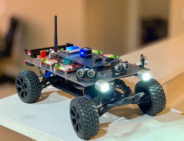
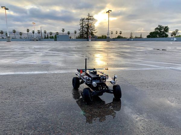
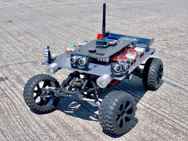
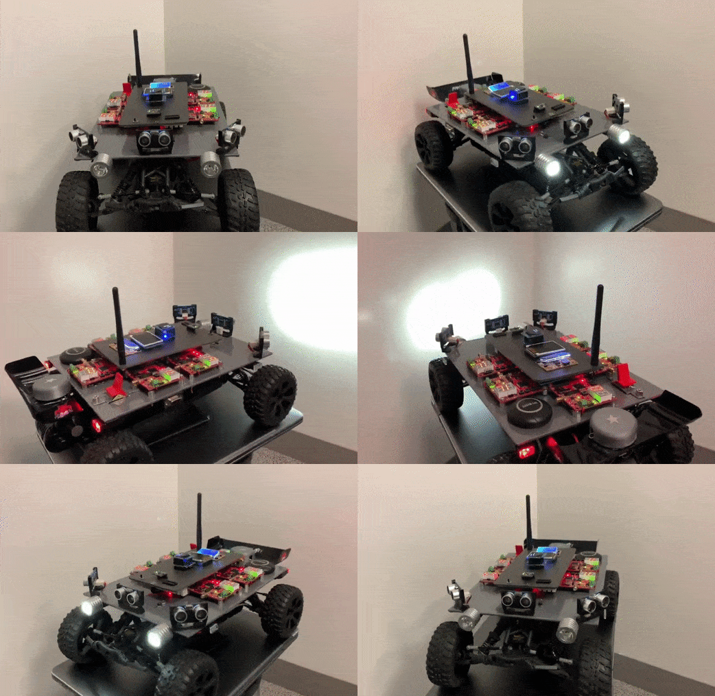
S19: Mystery Machine
Contents
Abstract
Recent advances in object scanning technologies and proliferation of self-navigating techniques have created new opportunities for developing autonomous vehicles which would reduce operation cost, improve safety and reliability while enabling autonomous transit service. A cutting edge self-navigating vehicle consisting of several embedded system paradigms in coherence with each other has been presented by a team of avid automotive enthusiasts implemented using a highly Test Driven Development approach.
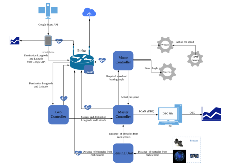
This project demonstrates a plurality of concepts related to autonomous vehicles which are capable of percepting and reacting to ever-changing surroundings in real time. It comprises of several interconnected ECUs communicating over the CAN bus where each module has specific roles which are GPS navigation, perception, mobility, cloud-based telemetry and master controller which will process data from all the modules and make intelligent decisions for enhanced control. This shall enable the car to navigate autonomously to the required destination which the user can remotely enter from the smartphone application. After which the car shall use the stipulated algorithm to calculate the shortest possible path to navigate towards the end point. While maneuvering through all kind of terrains the car will avoid any unexpected obstacles and notify the user on the smartphone application when it reaches the checkpoint and final destination.
Introduction
The objective of this project was to create an autonomous self-driving car which was able to reach the target destination while avoiding obstacles through the terrain. In order to accomplish this, five SJ One boards were used that handled separate functionality of the car:
- Master Controller
- Sensor Controller
- Geo Controller
- Bridge Controller
- Android Application
- Motor and Steering Controller
Team Members & Responsibilities
- Neeraj Dhavale
- Master Controller [SPOC]
- Geo Controller [SPOC]
- Sanket Patil
- Bridge Controller [SPOC]
- Hardware integration and PCB [SPOC]
- Tarun Chawla
- Motor and Steering Controller [SPOC]
- Geo Controller
- Rachit Mathur
- Motor and Steering Controller
- Documentation [SPOC]
- Adithya Baskaran
- Sensor Controller [SPOC]
- Hardware integration and PCB
- Sudarshan Aithal
- Sensor Controller
- Motor and Steering Controller
- Chithambaram Singaravelu Poonkodi
- Android Application [SPOC]
- Git Management [SPOC]
- Sai Kiran
- Testing [SPOC]
- Geo Controller [SPOC]
- Documentation [SPOC]
Schedule
| Week# | Start Date | End Date | Task | Status |
|---|---|---|---|---|
| 1 |
|
|
|
|
| 2 |
|
|
|
|
| 3 |
|
|
|
|
| 4 |
|
|
|
|
| 5 |
|
|
|
|
| 6 |
|
|
|
|
| 7 |
|
|
|
|
| 8 |
|
|
|
|
| 9 |
|
|
|
|
| 10 |
|
|
|
|
| 11 |
|
|
|
|
| 12 |
|
|
|
|
| 13 |
05/10/2019 |
05/14/2019 |
Design and implementation of exterior body |
Completed |
| 14 |
05/17/2019 |
05/18/2019 |
Resolve any issues before Final Demo |
Completed |
| 15 |
05/22/2019 |
05/22/2019 |
FINAL DEMO |
Completed |
Parts List & Cost
| Item# | Part Desciption | Vendor | Qty | Cost |
|---|---|---|---|---|
| 1 | RC car: - Redcat Piranha | RedCat Racing | 1 | $123.89 |
| 2 | CAN Transceivers MCP2551-I/P | Amazon | 10 | $9.99/piece |
| 3 | Ultrasonic Sensors | Amazon | 5 | $8.78 |
| 4 | NiMh Battery 5000mAh | Amazon | 1 | $33.41 |
| 5 | DB9 Female Connector | Amazon | 1 | $6.50 |
| 6 | Acrylic sheet | Amazon | 1 | $7.95 |
| 7 | Motor Driver | Amazon | 10 | $13.59 |
| 8 | USB LED Lights | Amazon | 6 | $6.99 |
| 9 | USB Headlamps | Amazon | 2 | $7.99 |
| 10 | Antenna | Amazon | 1 | $10.49 |
| 11 | Female USB Sockets | Amazon | 10 | $6.99 |
| 12 | Wifi module | Amazon | 10 | $5.99 |
| 13 | GPS Module | Amazon | 5 | $8.78 |
| 14 | Compass MPU9250 | Amazon | 1 | $18.91 |
| 15 | DC - DC Convertor | Amazon | 1 | $17.98 |
| 16 | SJ One board | From Preet | 5 | $80/piece |
| 17 | LCD Display | Adafruit | 1 | $19.99 |
| 18 | Misc. (Wires, switches, fuse, screws) | Excess Solutions | - | $20.00 |
| 19 | Carbon Fiber vinyl | Amazon | 1 | $11.99 |
| Total | - | - | $961.40 |
Design and Architecture
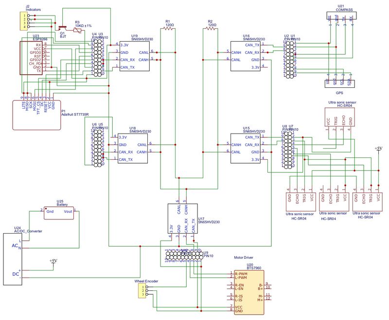
Hardware Schematic
CAN Communication
Hardware Design
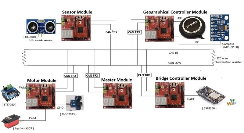
System Nodes: SENSOR, MOTOR, GEO, BRIDGE, MASTER
CAN(Controller Area Network) is a Broadcast Bus which is heavily used in the automotive industry. It defines protocol and hardware interface. It operates in standard baudrates like 100k, 125k, 250k, 500k or 1M bps. CAN uses half-duplex communication over a differential pair. The number of nodes affect the cable length because more CAN transceivers add more capacitance to the bus.
An MCU can be interfaced to CAN bus using CAN transceiver and terminated on each end with 120-ohm resistors. Resistors are used to avoid signal reflexion. CAN is frame based communication where each frame contains ID, length(DLC), and up to 8 data bytes. Message ID field can be 11-bit or 29-bit. Only one transmitter can transmit at a time which has the highest priority will go ahead first. Low priority message ID's will back-off.Lower message ID wins i.e zero is dominant.
Each node asserts an ACK if it receives a good frame. The software may or may not accept the frames. If no one ACKS, then the message is retransmitted. Depending on the CAN specifications retransmission error can be sent and can eventually lead to "Bus off" state.
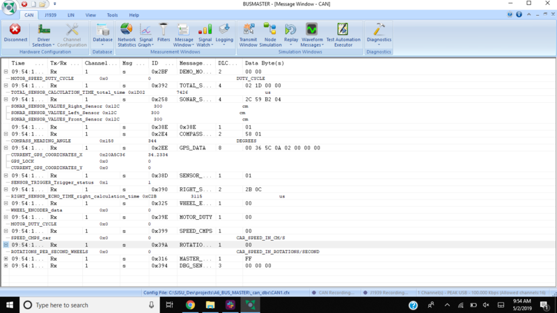
DBC File
BU_: DBG DRIVER MASTER IO MOTOR SENSOR LIGHT BRIDGE GEO GATEWAY

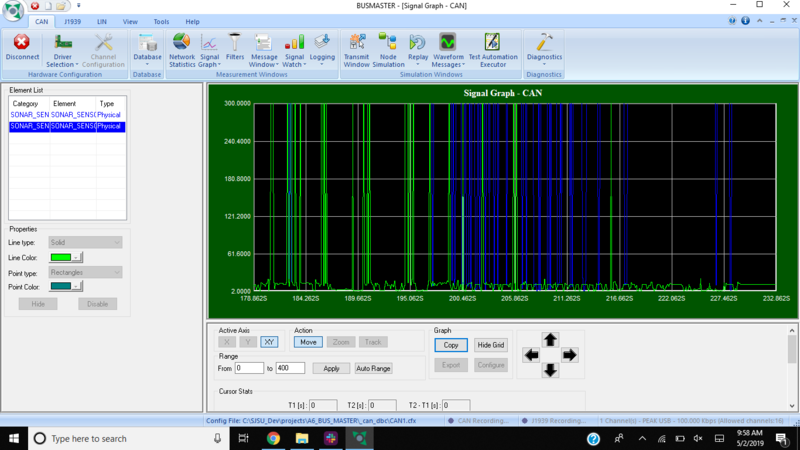
BO_ 600 SONAR_SENSOR_VALUES: 4 SENSOR
 SG_ SONAR_SENSOR_VALUES_Left_Sensor : 0|9@1+ (1,0) [0|300] "cm" BRIDGE,MASTER
 SG_ SONAR_SENSOR_VALUES_Right_Sensor : 9|9@1+ (1,0) [0|300] "cm" BRIDGE,MASTER
 SG_ SONAR_SENSOR_VALUES_Front_Sensor : 18|9@1+ (1,0) [0|300] "cm" BRIDGE,MASTER

BO_ 601 DEMO_IR_SENSOR: 6 SENSOR
 SG_ LEFT_SENSOR : 0|16@1+ (1,0) [0|0] "LEFT_VALUES" MASTER
 SG_ RIGHT_SENSOR : 16|16@1+ (1,0) [0|0] "RIGHT_VALUES" MASTER
 SG_ FRONT_SENSOR : 32|16@1+ (1,0) [0|0] "FRONT_VALUES" MASTER

BO_ 602 SONAR_SENSOR_THRESHOLD: 3 BRIDGE
 SG_ UPDATE_THRESHOLD_VALUE_Left : 0|8@1+ (1,0) [0|0] "cm" MASTER
 SG_ UPDATE_THRESHOLD_VALUE_Right : 8|8@1+ (1,0) [0|0] "cm" MASTER
 SG_ UPDATE_THRESHOLD_VALUE_Front : 16|8@1+ (1,0) [0|0] "cm" MASTER

BO_ 603 STEER_CMD: 1 SENSOR
 SG_ SENSOR_STEER_DIRECTION : 0|8@1+ (1,0) [0|0] "DIRECTION" MASTER,BRIDGE

BO_ 604 SONAR_REVERSE_SENSOR: 2 SENSOR
 SG_ SONAR_REVERSE_SENSOR_value : 0|9@1+ (1,0) [0|300] "cm" BRIDGE,MASTER

BO_ 700 MOTOR_SPEED: 1 MASTER
 SG_ MOTOR_SPEED_speed_in_mps : 0|8@1+ (0.01,0) [0|2] "mps" MOTOR,BRIDGE

BO_ 701 STEER_DIRECTION: 2 MASTER
 SG_ STEER_DIRECTION_ANGLE : 0|16@1- (1,0) [0|0] "ANGLE" MOTOR,BRIDGE

BO_ 702 DEMO_STEER_DIRECTION: 2 MASTER
 SG_ STEER_DUTY_CYCLE_VAL : 0|8@1+ (0.01,0) [0|0] "DUTY_CYCLE" MOTOR,BRIDGE

BO_ 703 DEMO_MOTOR_SPEED: 2 MASTER
 SG_ MOTOR_SPEED_DUTY_CYCLE : 0|8@1- (1,0) [-127|127] "DUTY_CYCLE" MOTOR,BRIDGE

BO_ 704 MOTOR_FLAG: 1 MOTOR
 SG_ REVERSE_FLAG : 0|8@1+ (1,0) [0|0] "MOTOR_FLAG" MASTER,BRIDGE

BO_ 740 COMPASS_DATA: 2 GEO
 SG_ COMPASS_HEADING_ANGLE : 0|9@1+ (1,0) [0|0] "DEGREES" MASTER,BRIDGE

BO_ 750 GPS_DATA: 8 GEO
 SG_ GPS_LOCK : 0|1@1- (1,0) [0|0] "" MASTER,BRIDGE
 SG_ CURRENT_GPS_COORDINATES_X : 8|28@1- (0.000001,0) [36.000000|38.000000] "" MASTER,BRIDGE
 SG_ CURRENT_GPS_COORDINATES_Y : 36|28@1- (0.000001,0) [-122.000000|-120.000000] "" MASTER,BRIDGE

BO_ 751 TELEMETRY: 8 GEO
 SG_ DISTANCE_TO_DEST : 0|8@1+ (1,0) [0|0] "" MASTER,BRIDGE

BO_ 790 MASTER_HEARTBEAT: 1 MASTER
 SG_ HEART_BEAT : 0|8@1+ (1,0) [0|0] "MASTER_HEARTBEAT" BRIDGE

BO_ 800 APP_CMD: 2 BRIDGE
 SG_ START_COMMAND : 0|8@1+ (1,0) [0|0] "" MASTER
 SG_ ABORT_COMMAND : 8|8@1+ (1,0) [0|0] "" MASTER

BO_ 805 WHEEL_ENCODER: 1 MOTOR
 SG_ WHEEL_ENCODER_data : 0|7@1+ (1,0) [0|0] "" MASTER,BRIDGE

BO_ 810 APP_DESTINATION_GPS: 8 BRIDGE
 SG_ DEST_GPS_COORDINATES_X : 0|28@1+ (0.000001,0) [0|0] "" GEO
 SG_ DEST_GPS_COORDINATES_Y : 28|28@1+ (0.000001,0) [0|0] "" GEO

BO_ 909 SENSOR_TRIGGER: 1 SENSOR
 SG_ SENSOR_TRIGGER_Trigger_status : 0|1@1+ (1,0) [0|1] "" BRIDGE

BO_ 908 SENSOR_INIT: 1 SENSOR
 SG_ SENSOR_INIT_init_Status : 0|1@1+ (1,0) [0|1] "" BRIDGE

BO_ 910 SENSOR_TIMEOUT: 1 SENSOR
 SG_ SENSOR_TIMEOUT_left : 0|1@1+ (1,0) [0|1] "" BRIDGE
 SG_ SENSOR_TIMEOUT_center : 2|1@1+ (1,0) [0|1] "" BRIDGE
 SG_ SENSOR_TIMEOUT_right : 3|1@1+ (1,0) [0|1] "" BRIDGE
 SG_ SENSOR_TIMEOUT_reverse : 4|1@1+ (1,0) [0|1] "" BRIDGE

BO_ 911 LEFT_SENSOR_ECHO_TIME: 2 SENSOR
 SG_ LEFT_SENSOR_ECHO_TIME_left_calculation_time : 0|16@1+ (1,0) [0|0] "us" BRIDGE

BO_ 912 RIGHT_SENSOR_ECHO_TIME: 2 SENSOR
 SG_ RIGHT_SENSOR_ECHO_TIME_right_calculation_time : 0|16@1+ (1,0) [0|0] "us" BRIDGE

BO_ 913 CENTER_SENSOR_ECHO_TIME: 2 SENSOR
 SG_ CENTER_SENSOR_ECHO_TIME_center_calculation_time : 0|16@1+ (1,0) [0|0] "us" BRIDGE

BO_ 917 REVERSE_SENSOR_ECHO_TIME: 2 SENSOR
 SG_ REVERSE_SENSOR_ECHO_TIME_reverse_calculation_time : 0|16@1+ (1,0) [0|0] "us" BRIDGE

BO_ 914 TOTAL_SENSOR_CALCULATION_TIME: 4 SENSOR
 SG_ TOTAL_SENSOR_CALCULATION_TIME_total_time : 0|32@1+ (1,0) [0|0] "us" BRIDGE

BO_ 915 PERIODIC_SCHEDULER_INIT: 1 SENSOR
 SG_ PERIODIC_SCHEDULER_INIT_scheduler_init_status : 0|1@1+ (1,0) [0|1] "" BRIDGE

BO_ 916 DBG_SENSOR_THRESHOLD: 4 MASTER
 SG_ THRESHOLD_VALUE_Left : 0|8@1+ (1,0) [0|0] "SONAR_DBG" BRIDGE
 SG_ THRESHOLD_VALUE_Right : 8|8@1+ (1,0) [0|0] "SONAR_DBG" BRIDGE
 SG_ THRESHOLD_VALUE_Front : 16|8@1+ (1,0) [0|0] "SONAR_DBG" BRIDGE
 SG_ THRESHOLD_VALUE_Reverse : 24|8@1+ (1,0) [0|0] "SONAR_DBG" BRIDGE

BO_ 921 SPEED_CMPS: 1 MOTOR
 SG_ SPEED_CMPS_car : 0|7@1+ (1,0) [0|0] "CAR SPEED IN CM/S" MASTER,BRIDGE

BO_ 926 MOTOR_DUTY: 1 MOTOR
 SG_ MOTOR_DUTY_CYCLE : 0|7@1+ (1,0) [0|1] "" MASTER,BRIDGE

BO_ 922 ROTATIONS_PER_SECOND: 1 MOTOR
 SG_ ROTATIONS_PER_SECOND_WHEELS : 0|7@1+ (1,0) [0|0] "CAR SPEED IN ROTATIONS/SECOND" MASTER,BRIDGE

BO_ 923 STEER_DUTY_LEFT: 1 MOTOR
 SG_ DUTY_CYCLE_LEFT : 0|7@1+ (1,0) [0|1] "" MASTER,BRIDGE

BO_ 924 STEER_DUTY_RIGHT: 1 MOTOR
 SG_ DUTY_CYCLE_RIGHT : 0|7@1+ (1,0) [0|1] "" MASTER,BRIDGE

BO_ 925 STEER_DUTY_CENTRE: 1 MOTOR
 SG_ DUTY_CYCLE_CENTRE : 0|7@1+ (1,0) [0|1] "" MASTER,BRIDGE
Sensor ECU
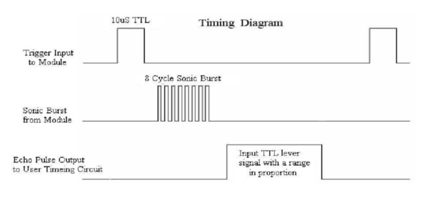
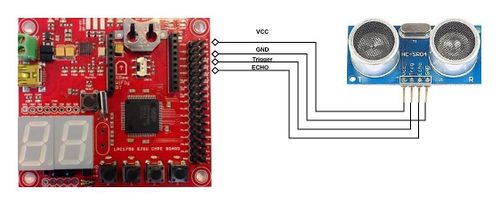
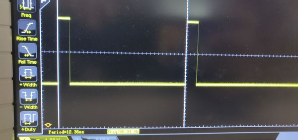
Ultrasonic sensors are great tools to measure distance without actual contact. Basic principal of ultrasonic distance measurement is based on ECHO and Trigger pins. Trigger pin is used to TRIGGER the sonar wave to ECHO through deflection. ECHO goes high as soon as it sends Sonar wave. Once it receives the wave the ECHO pin will go low. We will measure this ECHO HIGH period and use to calculate the distance.
Hardware Design
For object detection we are using ultrasonic sensors, three in the front (LEFT, RIGHT and CENTER) and one behind to measure the distance of each object. If an object is present in front of the sensors' general direction, sonor signals hits the object and reflects back. The sensor each have a specific threshold beyond which the car is supposed to react and avoid obstacles by altering the direction of travel.
Hardware Interface
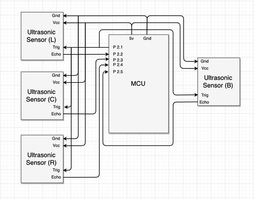
The trigger pin is common since all the sensors are activated at the same time. Echo in are individual and processed in parallel.The CAN connections are same as every other module.
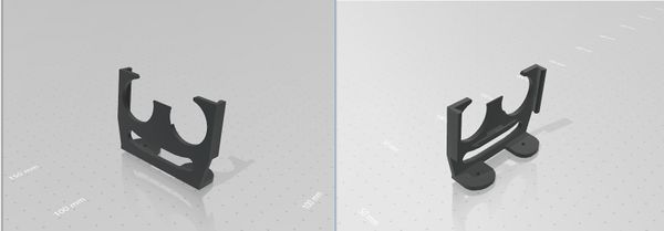
In order to raise the sensor at a height decent enough to detect obstacles directly ahead of the RC car, we designed custom 3D printed mounts for all the sensors. These stand provided a rigid support for these sensors as well as ensured that the sensors would survive an accidental head-on crashes.
Screenshots of these custom mounts can be seen along side.
Software Design
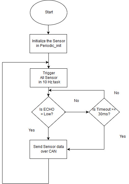
Sensors are calculated over in 10hz periodic task and sent to master module by use of the CAN connections between them every 20hz or 50ms period. All sensors are triggered simultaneously and calculated sequentially. GPIO protocols are used to set pins high or low. 8ms timeout is implemented for each sensors to avoid task overrun.
Implementation
In 100 Hz, Through the GPIO pin TRIGGER signal is sent and waits fro the ECHO signal to be created . If the timeout function runs out before the Echo completes the minimum distance is said to be obstacle free. If not the time taken for the signal to go high and then low is calculated with respect to speed of sound.
In 20 Hz, the data is sent through the CAN messages from the sensor module to the master and Bridge module.
Pseudo Code:
void 10hz_task(int count){
    initialize the sensors;
    Reset_flags;
    Trigger each sensors;
    calculate the distance;
    if( timeout){
          capture current value;
          set flags;
    }
    send distance values over can;
}
Technical Challenges
Initially we went with sharp 2YOA21 IR sensor to obtain better precision. But the range of the sensor was 48cm which was not reliable distance for obstacle detection. We upgraded to an Ultrasonic sensor which had trouble with echo reception due to faulty firmware code.
Unreliable sonor sensors
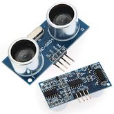
We upgraded to an Ultrasonic sensor HC-SR04 which had a better range of around 200cm with reliable precision. There was some faulty firmware code in the ultrasonic sensor due to which echo pin did not receive the signal for a long duration of time. We had 3 Ultrasonic sensors working together and each received other's echo signals sometimes due to reflection.
Solution
To solve the reflection problem, we elevated the sensor position and changed the direction of the sensor. To solve the faulty firmware, we introduced a timeout of 8ms in the code and if we don't receive the echo pulse within the timeout, it will give a distance of 110cm corresponding to 8ms.
Motor ECU
DC Motor
Our car arrived with an in-built Electronic Speed Controller(ESC) that was responsible for controlling the steering servo motor and running the DC motor attached to the rear wheels. Along with the motor control, the ESC was also embedded with a receiver for the remote control that shipped with the car.
We realized that the ESC could not be tapped into by providing an external signal to the pin-heads available on the exterior. This external signal from a function generator gave unsatisfactory results when passed through the ESC but we did conclude the optimal frequencies at which both the motors worked satisfactorily.
A motor controller module was used for driving the DC motor. We experimented with the frequency input to the motor driver to run the motor at and found that it operated best at a high frequency of 4KHz.
Servo Motor
The servo motor was connected directly to the GPIO ports of the SJ One board.
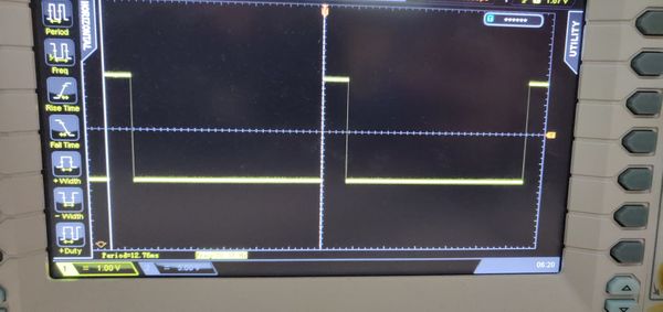
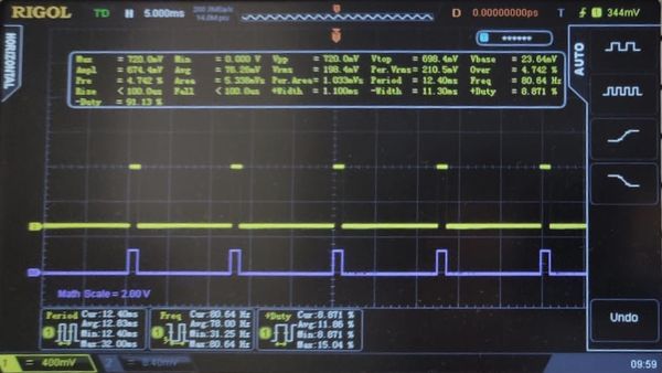
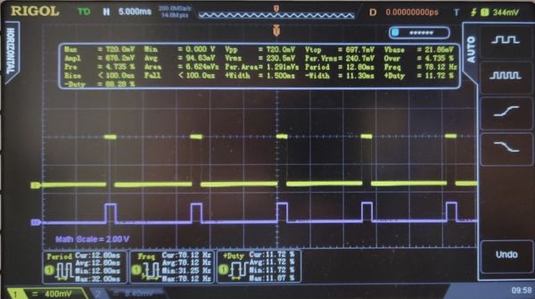
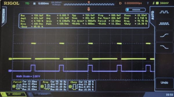
After applying an external PWM signal to the servo, we concluded that the servo motor was designed to work smoothly on 80Hz frequency. Accordingly, accurate values of the duty cycle were noted to get precise angles of the steering.
Encoder Sensor
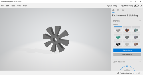
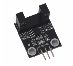
As part of speed feedback, we designed a custom encoder wheel between an encoder sensor mounted on the rear wheel shaft.
The wheel has a finite number of spokes which when intercepted by the encoder receiver, an interrupt signal is sent to denote one complete rotation.
These detected number of rotations were passed into a formula that calculates the wheel speed in cm/s.
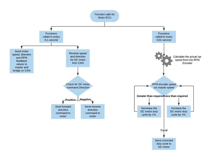
As part of the feedback, if the calculated wheel speed was not equivalent to the constant speed the PWM duty cycle was either increased or decreased to match the target.
A special scenario was also taken into consideration. If the speed of the wheel continued to remain zero after increasing the PWM duty cycle to the Maximum defined limit, then a reverse logic was called.
This case helped us in overcoming obstacles that were underneath the car and were initially not detected by the sensors.
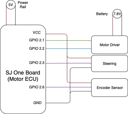
Hardware Design
Software Design
Technical Challenges and Solutions
- The primary challenge in the motor module was tapping into the ESC of the car but that was soon replaced by a Motor Driver module.
- While trying to run the motor driver module at a lower frequency of around 500Hz, we faced an issue of 'heat lock' where after 10 minutes the motor driver module would cut off the supply to the DC motor due to excessive heating. To fix this, we concluded that the motor driver module that we ordered worked best at a higher frequency upwards of 1KHz.
- We also learned about the limitation of the SJ One board in providing two PWM signals at different frequencies. To solve this, we temporarily attached the steering control with the Master Controller.
Geographical Controller
The Geographical controller is responsible for navigating the car in the direction of the destination selected in the Android app. It uses GPS module which gives the current location of the car and compass module for getting the heading angle of the car. After a destination location is selected in the Android app and sent, the module uses the shortest path algorithm to decide which checkpoint is closest to the destination. Geo controller uses its current location and the destination location(check point) to calculate the bearing angle and the distance to the destination. Subsequently, the heading angle and bearing angle are used to determine the angle that the car should turn, and is sent to the master module. On reaching the destination, the car will stop.
Hardware Design
Two modules are used in Geographical controller: GPS and Compass
GPS
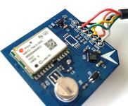
Ublox NEO-7M GPS Module is used for detecting the location of the car. This module returns NMEA string which needs to be parsed to get lock, latitude and longitude values from the module. To use the GPS string first we need to get a lock.
COMPASS
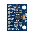
The MPU-9150 is the first integrated 9-axis MotionTracking device that combines a 3-axis MEMS gyroscope, a 3-axis MEMS accelerometer, a 3-axis MEMS magnetometer and a Digital Motion Processor hardware accelerator engine. The MPU9150’s 9-axis MotionFusion combines acceleration and rotational motion plus heading information into a single data stream for the application.
The MPU-9150 features three 16-bit analog-to-digital converters (ADCs) for digitizing the gyroscope outputs, three 16-bit ADC for digitizing the accelerometer outputs and three 13-bit ADC for digitizing the magnetometer outputs. For precision in the tracking of both fast and slow motions, the parts feature a user programmable gyroscope full-scale range of ±250, ±500, ±1000, and ±2000°/sec (dps), a user programmable accelerometer full-scale range of ±2g, ±4g, ±8g, and ±16g, and a magnetometer full-scale range of ±1200µT.
Communication with all registers of the device is performed using I2C at 400 kHz.
GPS module is interface over UART:
| GPS pins | SJOne Board |
|---|---|
| TX | P0.0 |
| RX | P0.0 |
| GND | GND |
| VCC | 3.3v |
Compass module is interfaced over I2C:
| Compass pins | SJOne Board |
|---|---|
| SDA | P0.0 |
| SCL | P0.0 |
Software Design
Flowchart
Implementation
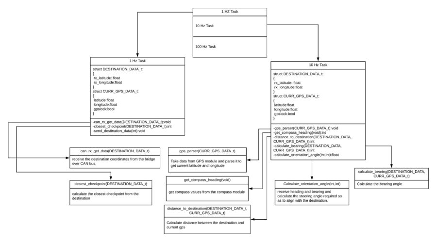
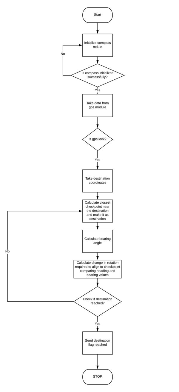
The current latitude and longitude position are obtained from GPS module and destination latitude and longitude should be received from the Bridge ECU over CAN bus. Then calculate the closest checkpoint with respect to the destination.We need to calculate the turn angle required so as to align with the checkpoint. Once the car is aligned with the destination, constantly check if the car is aligned with the destination using bearing and heading. Once the car is in 1 meter of range of checkpoint start moving towards the next checkpoint until the destination is reached.
The parameters required for navigation are:
Bearing Angle - the angle between the destination and our current location with respect to the North. The formula for the bearing is provided over here
Heading Angle- The angle with respect to the North in degrees. Received from compass module.
Angle to turn: We need to compute the angle that the car has to turn from its current heading to the bearing so as to align with the destination. Based on turn angle a steering value is selected so the car can align with the destination.
Distance Calculation- The distance between the destination and current coordinates by using the Haversine formula. The details about Haversine formula is available over here
Technical Challenges
Problem Summary:
- GPS data parsing issue: the GPS data would not be parsed because of timing issues.
- Compass values: The compass values were incorrect by 10 degrees or more.
- Checkpoint navigation: Deciding which checkpoint to go first so as to reach the destination with minimum distance. The returned values were not always desired.
Problem Resolution
- GPS data parsing issue: Calculate the time required to fill the UART buffer so that 10Hz task can use this buffer so as to parse it.
- Compass values: Implemented tilt compensation algorithm. The values received were very accurate.
- Checkpoint navigation: Took checkpoints every 15 meters.
Communication Bridge Controller
Design and Implementation
The main purpose of bridge controller is to establish communication from inter-modular CAN bus of the car to the smartphone application that connects to the bridge controller wirelessly via Wifi. After evaluating several options for communication module, ESP8266 was found to be most suitable to meet our practical requirements and usability for communication bridge. Wifi offers several advantages over bluetooth like better range, high speed and reliable communication without any data loss with low power consumption. It also supports multiple nodes with simultaneous connections where multiple users can monitor or control the car.
Hardware Interface
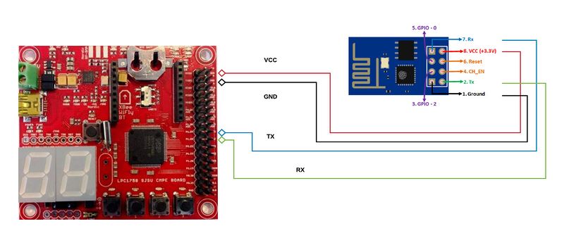
ESP8266 uses 3.3V DC power from SJone board. RX is connected to the TXD2 pin and the TX is connected to the RXD2 on the SJOne board for UART communication. It uses transmission rate of 115200bps that offers high speed communication capability.
ESP8266 Specifications
- WiFi 2.4 GHz, support WPA/WPA2, 802.11 b/g/n
- Integrated low power 32-bit MCU
- Integrated TCP/IP protocol stack
- Integrated TR switch, balun, LNA, power amplifier and matching network
- Integrated PLL, regulators, and power management units
- Support STA/AP/STA+AP operation modes
- SDIO 2.0, (H) SPI, UART, I2C, I2S, IR Remote Control, PWM, GPIO
- STBC, 1x1 MIMO, 2x1 MIMO
- Deep sleep power <10uA, Power down leakage current < 5uA
- Wake up and transmit packets in < 2ms
- Standby power consumption of < 1.0mW (DTIM3)
- +20 dBm output power in 802.11b mode
- Operating temperature range -40C ~ 125C
Software Design
Flowchart
MQTT Protocol
MQTT protocol was chosen as the communication protocol between the android application and WiFi module, since it is very light weight and is designed to support multiple nodes. For establishing the connection via MQTT an MQTT broker has to be implemented to which the clients can connect and start communicating. The MQTT protocol provides a lightweight method of carrying out messaging using a publish/subscribe model. Multiple clients can connect, publish and subscribe to predefined topics to share data amongst each other. This makes it suitable for embedded systems application messaging like low power sensors or mobile devices such as phones, embedded computers or microcontrollers.
Server Setup
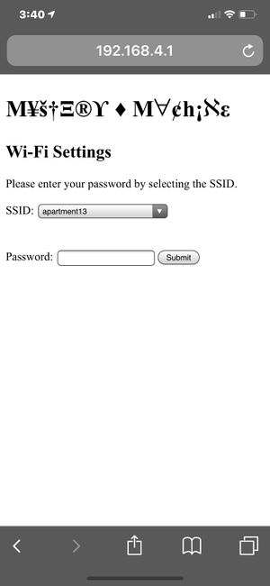
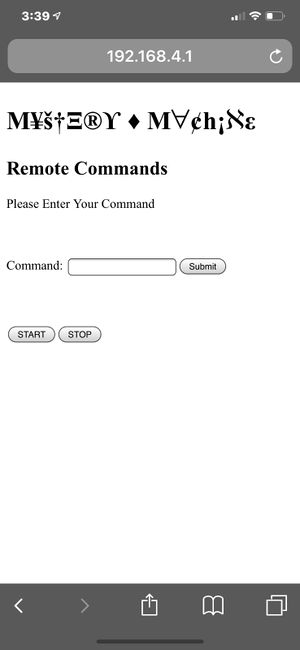
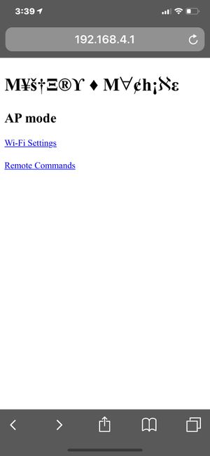
A local MQTT server was implemented using uMQTT library on the ESP8266 which allows the MQTT client to directly connect the car without any internet connection. The mobile application can connect directly to wifi module and establishes a connection to the MQTT server. Another cloud based server has been set up on Amazon EC2 instance using Eclipse mosquitto, an open source MQTT broker. This enable the user to remotely connect and operate the car from anywhere over internet. Additionally, local HTTP webserver has been implemented to make user operation smartphone platform agnostic.
Messaging Scheme
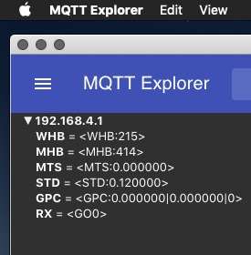
The data transfer in MQTT is done via topic scheme, where when a client has to send a message it has to publish the message with a topic. The communication takes place by a set of predefined topics which each of the clients listen to and publish their message. The client has to subscribe to topics to be able to receive the messages. Whenever a client publishes a message on a topic, every client subscribed to that topic will receive the message. The clients are not directly connected but in turn connected via the MQTT broker. Following is the messging scheme used for communication between the bridge controller and smartphone application.
Message Format & Topics for Bridge & App
Data sent from the car:
- Subscribe to Topic: HB
- Heartbeat msg (Detect the connection status with 3 sec timeout) <HB:XXXX>
- WHB : Wifi Heartbeat <WHB:XXXX>
- MHB : Master Heartbeat <MHB:XXXX>
- MTS : Motor Speed <MTS:XXXX>
- STD : Steering Direction <STD:XXXX>
- GPC : Current Location GPS Coordinates <GPC:XX.XXX|XX.XXX>
- TX : All debug messages
Commands/Data received from the App
- Publish on Topic: RX
- GO Command <GO1>
- ABORT Command <GO0>
- Destination GPS Coordinates <GPD:XX.XXX|XX.XXX>
- Waypoints GPS Coordinates with waypoint number <GPW:XX|XX.XXX|XX.XXX>
The message inside each topic is again formatted as below: “<COMMAND:value1|value2|value3”> Here the COMMAND is formatted as shown above. Each of these messages can have n number of values in them depending upon the type. For example the “COMPASS” type has only one value while the “SENSOR” has 4 values - one for each sensor in the car.
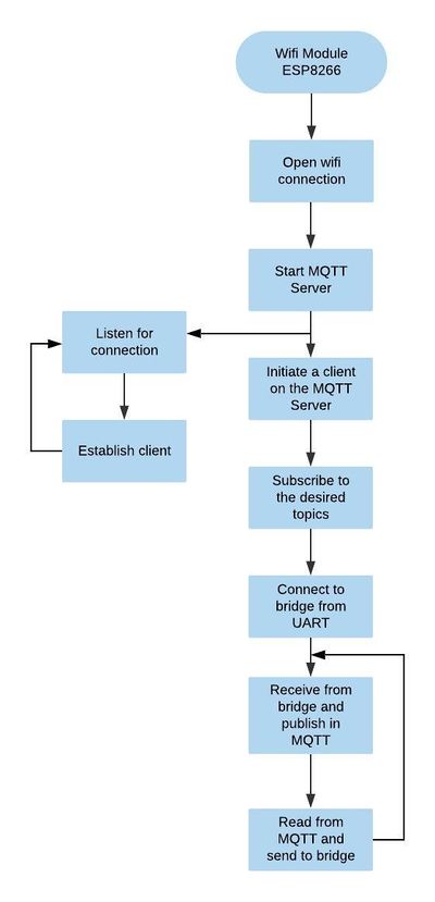
SJone board checks for a CAN message periodically, decodes it and sends this message to ESP8266 over UART.ESP8266 module checks for UART message periodically which is encapsulated in the predefined format to MQTT payload and publishes the message to the desired MQTT topic. Simultaneously the ESP8266 module receives the MQTT payload from smartphone application and decapsulates the message received on those specified topics. The decoded message is sent to the SJone board via UART which then encodes and sends this message over CAN bus.
Master Module
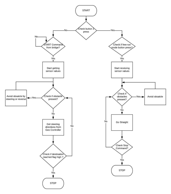
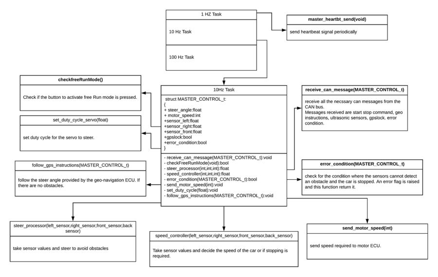
The master controller is responsible for the handling motion of the car. The master controller decides how the car will move based on inputs from all the other ECUs. The master first waits to receive the start command from the Android app via Bridge ECU. When the app sends “START Command” the master controller takes the values of ultrasonic sensors from the Sensor Controller, also the master takes the direction angles from the Geo controller. The master controller first calculates if there are any obstacles, it will avoid those obstacles by giving out motor speed values to the motor controller and steer accordingly. Then the master starts following the steer instructions provided by the Geo Controller. The obstacle avoidance algorithm preempts the GEO controller navigation directions.
Obstacle Avoidance
The obstacle avoidance algorithm implemented is simple. The master controller receives values of the ultrasonic sensors from the Sensor Controller. The values which are distances in centimeters are received from the front, left, right and back sensor. When the car is supposed to move forward the master checks the values of the front, left and right sensors and checks if all the values are above the threshold.
Hardware Design
Software Design
The pseudocode of steering is as below:
if(left sensor < threshold){
    STEER RIGHT();
}
if(right sensor < threshold){
    STEER LEFT();
}
else{
    Follow GPS_directions();
}
The pseudocode for speed controlling as below:
if(front_sensor < threshold){
    REVERSE();
}
else if(left_sensor && right_sensor < threshold){
    REVERSE();
}
Technical Challenges
Problem Summary
- Improper obstacle avoidance: obstacle avoidance would fail in narrow spaces.
- Obstacles below sensor level: The obstacles that lied below the sensors were not being detected which made the car get stuck in them
- Reverse steering logic: While the car had to reverse because of obstacles the steering during this time was wrong making it go in the obstacles again.
- Late response to sensor values: The car would not get enough response time to avoid obstacles during fast speed.
Problem Resolution
- Improper obstacle avoidance: Implemented a very simple algorithm with minimal if conditions for avoiding obstacles instead of multiple if,else-ifs conditions.
- Obstacles below sensor level: If the car would get stuck in such obstacles the motor ECU would identify that this is not a ramp and it's actually an error condition and send an error flag. The master would check this flag periodically and whenever it's high the master would make a reverse.
- Reverse steering logic: The steering logic must be mirrored how it is implemented in forward condition.
- Late response to sensor values: The threshold at which the sensors should response will change with respect to the speed it is at.
Mobile Application
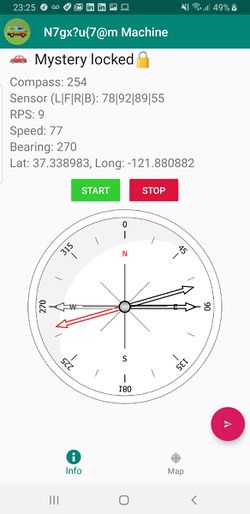
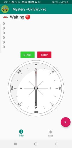
The Android application(Mystery Mobile) allows the user to interface with the RC car. The connection between the car and the mobile is established via MQTT protocol. The app requires that the mobile is connected to the Mystery Machine wifi that is hosted by the wifi modules mounted on the car. Then the app automatically connects to the car via the MQTT broker.
Eclipse Paho Java Client library is used for establishing the connection to the MQTT server. The library provides all the APIs required to connect, subscribe and publish messages. Once connected the app takes part in a two-way communication that allows it to send commands to the car and to receive information from the car.
Since the MQTT server does not provide the connection details of the other clients that is connected to it, we are using a heartbeat message from the wifi module to ensure that the Android application can know the connection status of the car.
Activities
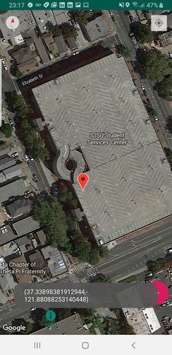
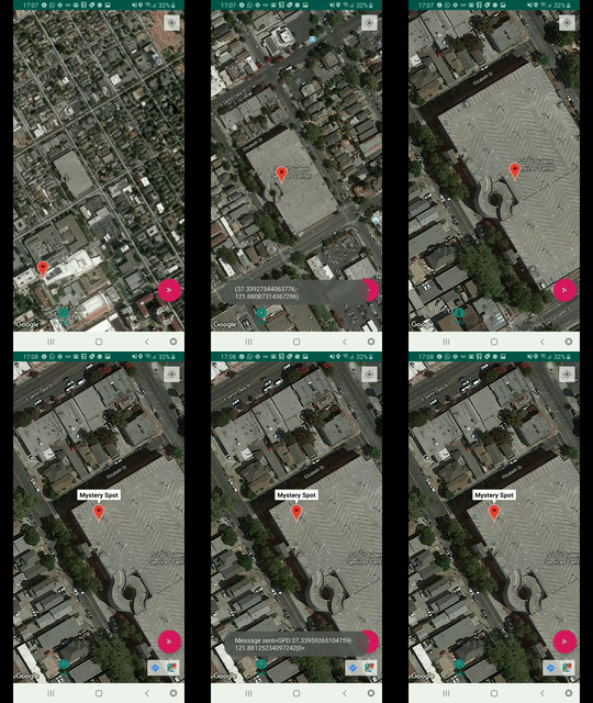
The app has one main activity and two fragments inside the main activity. Display fragment displays all data it gets from the RC car. It has buttons to start and stop the car. Map fragment has the Google maps view in it. Allows the user to know the current location. The destination for the car is set using a marker that can be placed on the satellite image on the map. The destination is sent when the send button is pressed.
Transmission
- App sends the GO and STOP commands that starts and stops the motor accordingly
- The messages are <GO0> for stop and <GO1> for start
- Sends the destination coordinates that corresponding to the location of the marker in the map fragment
- The message is <GPS:latitude|longitude>
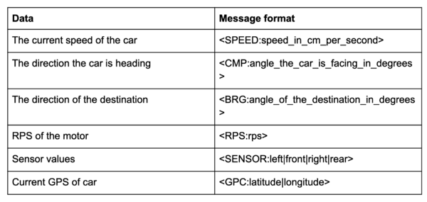
Reception
- The current speed of the car
- The direction the car is heading
- The direction of the destination
- RPS of the motor
- Sensor values
- Current location of the car
Software Design
Implementation
Technical Challenges and Solutions
- Integrating the map into the app was difficult since the application was designed with fragments and the Google map was an activity on its own, integrating it with the other fragments was complicated since it has to send the destination coordinates using the paho library.
- Solved it by converting everything into fragment including the map and a common fragment container.
Improvements
The app now connects directly to the car via the wifi hosted by the car. It can be improved by connecting the car to the cloud and there by the app can connect to the car from any where by connecting to the cloud. To achieve this the MQTT server should be run in a cloud instance and both the mobile and RC car acts as clients.
Conclusion
The project gave us a platform to learn how to coordinate as a team, introduction to new technologies and meeting real-time deadlines. Every individual who worked for this project had their own responsibilities and goals to accomplish. We got to know what team management is and how we can accomplish a goal by working as a team. We were more efficient and learned more stuff by working as a team. We faced many technical difficulties and failures throughout this project through which we learned a lot. We got to know how to manage the time and meet the deadlines. By designing and implementing a self-driving car from scratch, we realized that not everything will go according to plan even if it is full-proof, we need to improvise and keep moving forward. We learned to realize that everyone in a team will have their own skills and expertise that we need to navigate between them if we need to accomplish something bigger than any single individual. When being accused of a module not working, we recognized not to ask for proof of it not working but instead to show the proof that it does work as intended. Overall this project was a great learning experience.
Project Video
Project Source Code
Advise for Future Students
1. Start as soon as possible.
2. Don't go with cheap modules and cheap sensors. They might work but you will spend a lot of time trying to get them to work.
3. Follow the guidelines that Preet provides, it will save you time.
4. Unit testing was critical. The unit test helped a lot with debugging and modularizing the code.
5. Keep it simple and modular. Don't create "GOD OBJECTS". Use meaningful and descriptive names for functions and variables. Don't make it too complex.
6. Code review sessions from Preet helped a lot. You will get a lot of insight into making your code better.
7. Never stop improving on any particular module just because it works.
8. Have a bigger picture of the whole design before beginning (Especially in Hardware design )
9. Keep team deadlines other than Preet's deadlines.
10. Celebrate even the smallest of accomplishments, it will help with the team morale.
Acknowledgements
We would like to thank our professor, Preetpal Kang for his guidance and feedback along with prompt replies in slack. We had continuous feedback after ever demo and tips that helped us identify problems ahead of time. We would also like to thank the ISA Pratap Desai for his inputs as based on his current and previous experiences. We would also like to show our gratitude for all the help presented by our classmates helping out each other when we were stuck.
References
HC-SR04 DataSheet
Ublox-7M Datasheet
MOC-70T3 Datasheet
MTU-9150 Reference sheet
ESP-8266 Datasheet

