S16: SkyNet
Contents
SkyNet
Abstract
SkyNet is a tracking camera mount that follows a given target using computer vision technologies. The system utilizes two stepper motors that are controlled by inputs given from a Raspberry Pi 3. The Raspberry Pi 3 utilizes the OpenCV open source library to calculate the deviation of a tracked object from the center of its view. System then control the motors to correct the camera position such that the target is aligned to the center of the video. The mount will be able to hold any standard 5-inch phone or small point and shoot for video recording. The completed project was able to hold any smartphone and small point and shoot cameras. The system allowed for limited pitch rotation and unlimited yaw rotation. The tracking solution used an OpenCV method called haar cascade. The tracking was adequate enough to track a slow moving target and had issues with backgrounds of similar color to the tracked person.
Objectives & Introduction
The objective of this project was to create a tracking camera mount that kept a target within the center of the camera's view at all times. To accomplish this a custom frame was created to house a stepper motor system and an OpenCV based tracking solution. The project has a custom frame that was modeled in a CAD software called Fusion360 and printed using a 3D printer. The stepper motor system consists of two motors for yaw and pitch rotation. The OpenCV tracking software was run on a Raspberry Pi 3 that used the Raspberry Pi camera as an input to the software.
Team Members & Responsibilities
There were four team members in this project and two teams of two were created for each part of the project. One team was focused on creating an OpenCV based tracking solution. The other team was focused on creating a physical system for the tracking software to control. The breakdown of the teams is shown below.
OpenCV tracking solution
- Steven Hwu
- Jason Tran
Motor System and frame
- Andrew Herbst
- Vince Ly
Motor System
The objective of the motor system was to create a system that allowed yaw and pitch rotation. The system was designed to be place on a table or a tripod at chest level. The frame that held the system was designed to use the least amount of material and allow for unobstructed rotation on either axis. To accomplish this stepper motors will be placed horizontally and vertically. Stepper motors are ideal for an accurate system like this because of the simple control scheme. Also stepper motors are very accurate because they rotate in steps and can micro-step to decrease the jitter of motor movement. A Raspberry Pi 3 was the processing platform chosen. This platform runs linux and had the bare minimum performance to run an OpenCV tracking solution. To power the system a power circuit was created to power the motors and the Raspberry Pi. Ideally the system would include a battery but due to lack of time a power adapter supplied power to the system. This restricted the movement of rotation on the horizontal access.
The bare minimum requirements for the motor system is summarized below.
Specifications
- Allow for yaw and pitch rotation
- Small footprint of the entire system frame
- A compute platform capable of running OpenCV tracking code
- Power circuit to power two stepper motors/compute platform
Tracking system
The purpose of the tracking system is find the position of a target in a video source. A video source is a source of visual data in the form of a video file or a camera; in this case, SkyNet obtains its visual data from a camera. To analyze visual data, images are read from a video source in the form matrices. To track a target, it must be present and identified in an image/frame of a video source.
There are 4 candidate methods to identify and find the position of a target:
- Color Space Analyze: Analyze the color space of an image and detect the position of specific colors
- Template Matching: Provide a sample image of the desired object/target and find matches in an image
- Tracking API: A long-term tracking method that uses online training to define and detect the position of an object given many frames from a video source
- Haar Cascade Object Detection: Use an object classifier as a representation of an object, then detect the position of that object in an image
For this project, a target is identified using Haar Cascade object detection and is defined using an object classifier. Using a frontal face object classifier, the target to be tracked is the face of a person.
Schedule
| Week# | Due Date | Task | Completed | Notes |
|---|---|---|---|---|
| 1 | 3/29 | - Create Parts list and place order (Motors, Cameras, etc.)
- Compile OpenCV C++ code and run examples on Raspberry Pi 3 |
Completed | - Ordered parts on 3/27
- OpenCV library is building on both development PCs (Steven/Jason) TODO: - Run OpenCV on Raspberry Pi 3 |
| 2 | 4/5 | - Create motorized unit
- Create the CAD model for 3D printing - Create the breakout board for the motor controller - Be able to track an object in frame (Highlight object) |
Completed | - Successfully tracked an object in HSV color space.
- Successfully tracked human w/ various other objects. - Human tracking not enough to track one person, trying combination of HSV tracking - Initial CAD model created w/ Autodesk Fusion 360 - Created PCB for TI chip, looking for fab houses |
| 3 | 4/12 | - Test various motors for behavior/control
- Extrapolate movement of object |
Completed | - Looking into Stepper vs Servo vs Brushless for optimal control/smoothness
- Looking into face tracking as option - Researching how to narrow down human tracking to 1 specific person. |
| 4 | 4/19 | - Sync-up on how to command motors (scaling, etc.)
- Create API interface to control motors - Create communication tasks to control motors |
- Moving forward with Stepper motor implementation
- Using 12V wall adapter as power source, if time permits get a battery sytem - Aim to finish the frame by this weekend, Horizontal part prints on Saturday and Veritical part prints on Sunday - Developing HSV as fallback tracking - Moving forward with Machine learning implementation | |
| 5 | 4/26 | - Integration of control system and motor unit | Completed | - Push back integration to 5/3
- Tested stepper motor drivers |
| 6 | 5/3 | - Created motor system circuit design/wiring layout | Completed | - Pushed integration to 5/10 |
| 7 | 5/10 | - Finish motor system wiring
- Integration between motor system and tracking system |
Completed | - Pushed back optimization till 5/17 |
| 7 | 5/17 | - Motor system Optimization | Completed | - Finished motor system optimization
- tracking optimization on 5/22 |
| 7 | 5/22 | - tracking optimization | Completed | - Tracking with backgrounds similar color to person causes issues
- Turn on smartphone light to increase contrast between user and background - Motor system extremely hot, might have to do with current draw |
Parts List & Cost
ECU:
   RaspBerry Pi 3 Rev B ~$40
       - https://www.raspberrypi.org/products/raspberry-pi-3-model-b/
Tracking Camera:
   Raspberry Pi Camera Board Module ~$20
       - http://www.amazon.com/Raspberry-5MP-Camera-Board-Module/dp/B00E1GGE40
Stepper Motors:
   Nema 14 Stepper Motor (Pitch Motor)~$24
       - http://www.amazon.com/0-9deg-Stepper-Bipolar-36x19-5mm-4-wires/dp/B00W91K3T6/ref=pd_sim_60_2?ie=UTF8&dpID=41CZcFZwJJL&dpSrc=sims&preST=_AC_UL160_SR160%2C160_&refRID=0ZZRP157RFT10QDHHKN4
   Stepping Motor Nema 17 Stepping Motor (Yaw Motor) ~$13
       - http://www.amazon.com/Stepping-Motor-26Ncm-36-8oz-Printer/dp/B00PNEQ9T4/ref=sr_1_4?s=industrial&ie=UTF8&qid=1463981462&sr=1-4&keywords=stepper+motor+nema+17
Controllers:
   x2 DRV8825 Stepper Motor Driver Carrier, High Current ~$10
       - https://www.pololu.com/product/2133
Phone mount:
x1 Tripod phone mount ~$5
Whole Enclosure:
3D printed
Total: ~$123
Design & Implementation
Hardware Design
Frame
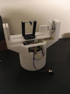
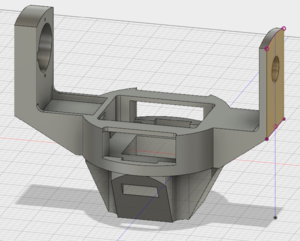
A custom frame was created to hold the motors and cameras in place. The frame was created in Fusion360, a CAD software for created 3D models. The design went through various changes and after two weeks a final design was created. The design was created with the intention to be as small as possible. Since the system used a large stepper motor for the horizontal rotation the frame ended up being very tall. One possible change in the future would be to add more functionality to the lower portion of the design.
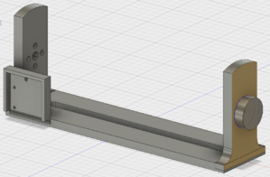
The frame design was created in four separate parts: horizontal frame, vertical frame, base, and base plate. The horizontal frame housed all of the electronics of the system. This included the Raspberry Pi 3, motor drivers, power circuit, pitch stepper motor, and yaw stepper motor. The vertical frame held the tracking camera and user camera in place. The vertical frame was attached to the pitch stepper motor. The base allowed the system to stand on its own and served as a intermediate connector to a possible tripod mount. The base plate was designed to cover the bottom of the base and allowed the system to be held by a tripod head.
Once the 3D model of the frame was completed it was printed using a 3D printer. The horizontal frame took the longest to print by taking 20 hours to complete. The vertical frame was a fraction of the time taking only 3 hours to print. The fastest part to print was the base which took about 2 hours to print because of its symmetrical shape. In total it took roughly 25 hours to print the entire frame for the project.
Power Unit
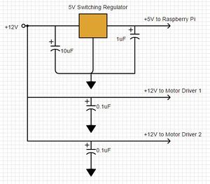
A +12V supply was needed to power both of the motor drivers. A +12V wall adapter was used along with a pair of coupling capacitors to run power to the DRV8825 IC's. In addition, a +5V supply was required to power the Raspberry Pi 3 board, which controls the motor drivers over GPIO. To step down the 12 volts from the wall adapter, we used a 5V switching regulator because it could handle the heat and power capacity that would be required when running the motors.
Motor Driver
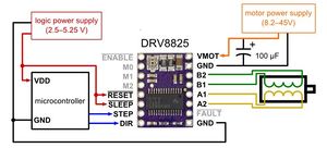
The TI DRV8825 IC is capable of driving a bipolar stepper motor, so two of these chips were implemented for the pitch and yaw motors. The controller was powered with a 12V supply, as shown in the figure. This specific motor driver was chosen primarily because of its simple STEP/DIR interface. The driver would receive a direction signal along with a PWM signal. The frequency of the PWM signal dictates the speed at which the stepper motor would turn in the direction specified by the DIR pin. The motor driver also had microstepping capabilities so that we could coordinate the steps per rotation of each motor to deliver the maximum smoothness while turning the motor. The breakout board that carried the motor driver allowed for easy implementation and connection to the Raspberry Pi and PWM driver.
Stepper Motors
Stepper motors were chosen for this project because of how simple it was to control and how smooth the rotation can be. These motors are easy to control because the commutation to rotate the motor is done simply by energizing opposite poles within the motor itself. Stepper motors are not ideal for driving things very fast but are great for rotating things very accurately. The stepper motors used in this project was a 200 steps per rotation and 400 steps per rotation motor.
Depending on the motor controller the system can take micro-steps, in other words fractions of a full step. For example, a 200 step motor can take half steps per each commutation. The motor will in total rotate within 400 steps since it takes twice as many steps at half-step sizes. For this project micro-stepping was a critical feature because it allowed for smoother rotations. Camera's recording video are notorious for picking up the slightest imperfection in motion. This is the reason why servos and dc motors were not considered for this project. Motion from those types of motors would be very jittery without very optimized motor controls. Brushless motors was also considered but are very hard to control at low speeds.
PWM Driver
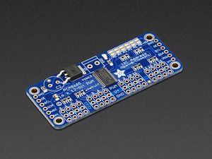
Because the Raspberry Pi 3 only has one hardware PWM output pin, an external PWM driver was chosen to drive the PWM signals that controlled the two stepper motors. The PCA9685 16-channel PWM controller was chosen as the interface between the microcontroller and the two stepper motors. The PWM controller communicates with the Raspberry Pi over the I2C bus with just two wires. With this device, the PWM frequency could be adjusted between 24Hz and 1526 Hz, which was an acceptable range for the application of this project. The frequency was set by modifying the register that dictated the frequency prescaler in the equation in figure 4.
Hardware Interface
Motor System Class
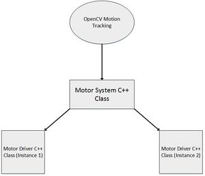
In order to communicate from the higher-level OpenCV motion tracking module to the lower-level motors, a Motor System class was developed in the intermediate layer. The Motor System class was developed with various functions that the motion tracking module would call upon to control the individual motors' movement. A summary of the basic functions the Motor System provided are below. The main purpose of the Motor System is to pass the speed and direction commanded by the OpenCV module to the individual motors and also to determine the motor step size that would produce the most refined movement of the motors. The motor system api was designed to be as simple as possible leaving users to only worry about what axis to rotate around and at what speed. The motor system hides the motor initialization and sets the most optimal motor settings in the background. The user can set a max rotation speed and the motor system will initialize the step size to the smoothest possible setting that also satisfies the max rotation speed.
// Motor System Class

    void power_off(void);

    void power_on(void);

    /**
     * Sets the speed for both the yaw_motor and pitch motor
     *
     * @param x_speed speed of horizontal motor
     * @param y_speed speed of vertical motor
     */
    void set_x_y_speed(float x_speed, float y_speed);

    /**
     * Checks if either system is faulted
     *
     * @return true if either motor is faulted
     */
    bool is_faulted();

    /*
    * Sets motor step size for maximum smoothness given minimum rotation time
    */
    void set_smoothness();
The Motor System is also responsible through its constructor for initializing the pitch motor and yaw motor by assigning each GPIO pin to its corresponding function in the Driver class.
// Motor Initialization:

    pitch_motor = new Motor_driver(PITCH_PHYSICAL_STEPS, PWM_0, PIN_2, PIN_3, PIN_21, PIN_22, PIN_23, PIN_24, PIN_0);
    yaw_motor   = new Motor_driver(YAW_PHYSICAL_STEPS, PWM_1, PIN_4, PIN_5, PIN_6, PIN_25, PIN_27, PIN_28, PIN_1);
Motor Driver Class
The Motor Driver class has two instances, one for each motor, which is passed information such as speed and direction from the Motor System functions. Below is a list of the important functions available to the Motor Driver, the most vital being the rotate() function which parses the x and y speed information from the Motor System class and sets the corresponding DIR pin and sets the frequency of the PWM signal to send to the motor to control speed.
// Motor Driver Class

     /**
     * Sets the rotation of the motor can either be
     * NEGATIVE, POSITIVE, or HOLD
     *
     * @param motion    specifies the type of motion
     * @param speed     Sets the speed of the motor, 0 <= speed >= 1000
     */
    void rotate(motion_e motion, int speed);

    /**
     * Sets the step size of the motor
     *
     * @param step_size_e step size for motor
     */
    void set_step_size(step_size_e step_size);

    /**
     * Sets the direction of the motor positive or negative
     *
     * @param motion    direction to move
     */
    void set_dir(motion_e motion);

    /**
     * Holds the current position motor is at, used for speed == 0
     *
     */
    void hold_position(void);
When the motors are initialized, the constructor carries out the following tasks:
   1. Set steps per rotation
   2. Set current motion to HOLD
   3. Set step size to 1
   4. Set current speed to zero
   5. Initialize the control pins of the motor driver to correspond to the GPIO pins of the Raspberry Pi
PWM Driver
The Raspberry Pi communicates with the PCA9685 PWM driver over the I2C bus through two wires, SDA and SCL. The microcontroller can manipulate the motor drivers by writing to different control registers on the PCA9685 in order to configure the output PWM and duty cycle to the motor drivers. For example, the sequence to set an output PWM frequency is as follows:
   1. Check that the requested frequency is within the boundary (24-1526 Hz) and clamp value if necessary
   2. Calculate prescaler based on requested frequency using formula from figure 4
   3. Set sleep mode bit by writing 0x10 to Mode 1 address 0x00
   4. Write the calculated prescaler value to the prescaler register at address 0xFE
   5. Clear the sleep bit by writing 0x00 to Mode 1 address 0x00
Software Design
Implementation
Tracking Application using Haar Cascade Object Detection
The main software consists of 4 major steps:
- Initialization
- Create a classifier object, then load a classifier file
- A classifier is an XML file that describes a particular object, for example, the full body of a person.
- Initialize the video source
- The video source is an object that represents the video capture device, for example, a USB camera. Real-world visual data as a matrix can be obtained from this object.
- Create a classifier object, then load a classifier file
- Get a image/frame from the video source
- Perform object detection on it
- Object detection is performed by searching the given frame for objects that match the previously loaded classifier file.
- After analyzing, a list of found targets is returned; found target are represented as Rectangle objects.
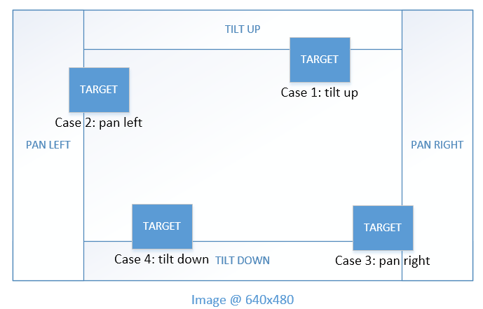
- Determine if the tripod’s camera needs to be rotated based on the target’s location in the frame.
- For each detected target in the found list, determine whether the tripod should pan or tilt.
- Currently, the tripod has the capability to pan/tilt in the following directions:
- Left
- Right
- Up
- Down
- If the panning/tilting action is required, activate the appropriate stepper motors (x-axis or y-axis)
Testing & Technical Challenges
OpenCV Tracking Methods and Challenges
Color Space Analysis
When we started working with OpenCV for our project, initial ideas and methods for tracking objects started with color space analysis using Hue, Saturation, and Value (HSV). Any RGB image can be converted into HSV which provides a better filter as the characteristic of color is only one attribute in HSV. However, in order to use an HSV filter, the HSV values must be adjusted properly for each object. We had to add some intelligence in deciding what should and should not be tracked. For proof of concept, we randomized the HSV filter until we detected one solid object in the center of the screen. This proved to be quite promising and since we developed this very early on, we decided to look into alternatives.
Color Space Analysis with Contours
The new HSV filter implementation would have more logic to deciding which object should be tracked. We decided to track any object that was moving and also in the center of the camera. The way we determine moving objects is by taking the difference between two frames and the moving object would be the difference. After, we find the contours of the difference image as this will outline the moving object. The built-in API for finding all points within a contour was very lacking. On forumns, the most commonly used method was to fill in the area within the contour with an uncommon RGB value: 0,255,0 (solid green) and for each exact match of solid green in the original image, the HSV value at that point will be stored. However, our contour had a lot of noise so instead of using the provided API to fill in the contours, we developed our own, and that was by filling in a convex polygon with the points generated by the contour. This filled in our moving object pretty well. We then populated a histogram of the HSV readings and chose to use the most prominent HSV ranges to track. To prevent noise from being tracked in our frame, we made sure to only track objects that were within the vicinity of the previous object being tracked. Using this method, we were able to track a moving object pretty reliably using our laptops.
Template Matching
This led us to look into template matching. With template matching, we would provide an image to the OpenCV code and it would try to find the image within the captured frame. To handle the possibility that the image could be constantly changing, we decided to constantly update the image being tracked with the best match. There were a couple of major issues with this method. First, if the object was slightly off the screen, the template matching would immediately start tracking the next best match, which was often a wall. It was very easy to start tracking the wrong object and there was no metric provided in the API to determine how close of a match the image was. In addition, this method was very CPU intensive as it took a heavy toll on our laptops. With only a couple weeks left, we decided to go back to HSV filters.
Tracking API
Tracking API is a type of object detection method that is available as a prototype module in the OpenCV extra modules repository. This module was designed to perform long-term tracking by using online training to dynamically define and track an object. In details, this module's algorithm uses a section of the video source to represent the object/target and uses the background as "negative" images. The quality and definition of the target's representation grows as more frames are used in this algorithm.
This method, however, introduces a critical issue. Because of CPU/GPU speed limitations, the Raspberry Pi 3 is not capable of processing enough frames for this algorithm to be effective. Low quality object definitions result in false positives, and therefore, compromises the tracking system.
Haar Cascade Object Detection
Using Color Space Analysis and object detection using Template Matching or Tracking API introduced critical issues:
For color space analysis
1. The robustness of the tracking system was compromised due to the amount of false positives.
For Template Matching and Tracking API
2. Utilizing the algorithm of Template Matching and Tracking API is very computationally expensive. Because the time it takes to analyze each frame is significantly long, the data received from the video source was approximately a few seconds (4s-6s) behind from real-time which makes it impractical to use.
Haar Cascade Object Detection solves these issues
The benefits of Haar Cascade Object Detection is that it was designed to perform object detection in the order of milliseconds. This is possible by using pre-trained object classifiers to efficiently and accurately define objects to look for given an image. The problem, however, is that in the scope of this project, using an object classifier limits the target to be a single type of object; in this case, the frontal face object classifier was used to target the face of a human.
Conclusion
This project gave the team a huge opportunity to develop embedded system skills as well as OpenCV computer vision programming. As this was the first time the team had designed and implemented a motor system and controls, this project presented many initial challenges. However, through much research, testing, and methodical design decision making, the team was able to successfully implement and control a set of stepper motors through a microprocessor and PWM driver. As OpenCV is becoming an innovative and popular tool in the industry, this project gave the team experience developing this cutting-edge motion tracking software. By working closely as a team in constant communication, component integration was seamless and the final product was very successful.
Project Video
Project Source Code
References
Acknowledgement
We would like to thank Preet for his guidance, support, and informative and organized guidance. His teaching helped us to further develop our passion for embedded systems and give us the opportunity to improve on skills to help us succeed in the industry.
References Used
Appendix
Meeting notes
| Date | Meeting Notes |
|---|---|
| 3/27 | Tracking:
   C++ for OpenCV
       Have target stand dead center and let the PC choose what to target
           - Green for go
           - red for lost
   Graceful halt, error compensation in OpenCV layer
Motor System: API for % speed for x and y axis x_axis_speed(int speed_percent) y_axis_speed(int speed_percent) "Dumb motor system" should not know about error or destination, only knows how fast to go in a direction Enclosure: Visible framework 3D printing Autodesk Fusion 360 |
| 4/3 | +++++++ Meetings Notes ++++++++
PCB Design - Completed Design for PCB - Initial quote was 18 per board - Looking into the price and seeing other fab house prices - Aiming to get PCB in 2 weeks time Motor controller - Going to use TI controller as base - Fallback is Servo Motors - Motors used in robotic arms? slow and percise - Will be using EVM from TI to test out TI behavior - Looking into other controllers to get desired result L6234, SPWM signals (Sine-wave PWM) CAD Frame - Re-adjust Raspberry Pi Cubby on Horizontal Frame - Add more support to Horizontal Frame arms - Aiming to get test print by next meeting, test durability. OpenCV - Trained model for people detection already exists
- How to differentiate a person? Premade function gives back a list of everyone
- We CAN detect people, We need to find out how to narrrow down the targets
- Use rectangles to get coordinates combined with HSV
- Combine coordinates, analyze with HSV
- HAR face tracking
- possibly can single out a target
|
| 4/10 | +++++++ Meetings Notes ++++++++
Hardware Side: Project Frame
- Successfully printed out Horizontal frame, approximately 9 hours to complete
- Used a SLA converter to get SLA file from 3D model in Fusion 360
- Used a slicer tool to create a sliced version of the model to use in the 3D printer
- Successfully drove a motor slow
- Used method detailed in this article http://www.berryjam.eu/2015/04/driving-bldc-gimbals-at-super-slow-speeds-with-arduino/
Raspberry Pi PWM
- Found two libraries to implement PWM control
Circuit diagram
- Started on full circuit diagram
Tracking: New ways of tracking
- Used frame difference tracking
- Pattern tracking
Template Matching and frame difference
- Look for frame differences and then choose objects based on the different objects in a frame
- Use template matching to then track the object that was choosen
Raspberry Pi Camera implementation
- Developed on laptop first and then moved to Raspberry Pi
- Heating issues on the Raspberry Pi
- Really bad performance capture at 20-30 frames
- Will get metrics of performance in next run
- Reduce the
Template Matching
- It can dictate anything as an object
- car, hand, etc.
- We have to select it to target
- Fast moving objects were still trackable
|
| 4/17 | +++++++ Meetings Notes ++++++++
Critical Meeting Hardware Side: Stepper motor control
- Accurate because of the way the motor is built
- Motors can be bought at various steps per rotation
- Microstepping can increase the amount of steps per rotation
Why switch from brushless motors?
- Brushless motor control is too inaccurate for camera control
- Voltage/current draw too large while using brushless
Power circuit
- Circuit to supply the power to the system
- The motors themselves have a max draw about 1 amp
- Raspberry PI needs minimum 5V and at max 1A
- Development phase use a 12V 3A wall adapter
- If time permits run system on battery power
Tracking: Template Matching inadequate
- Takes too much processing power
Machine Learning Training
- Offline training
- Online training (Real time training)
Fallback HSV tracking
- Will develop until it can be feasibly used
Min spec
- Tracking a student walking across the classroom
|
