S16: Ahava
Contents
- 1 VisionCar
- 2 Introduction
- 3 Schedule
- 4 Parts List & Cost
- 5 Design & Implementation
- 6 Integration & Testing
- 7 Conclusion
- 8 References
VisionCar
This project aims at tracking a known object from a vehicle and follow the target at a pre-fixed distance. The RC car is mounted with a camera which is interfaced to a Raspberry Pi Compute module. The Compute module performs the required image processing using OpenCV and provides relevant data to the Car Controller for driving. An Android Application is developed to allow a user to select an object by adjusting the HSV filter thresholds. These values are then used by the imaging application to track the desired object.
Introduction
Team Members & Responsibilities
| Team Member | Responsibilities |
|---|---|
| Aditya Devaguptapu | Compute Module board bring-up, Android application |
| Ajai Krishna Velayutham | Motor API Implementation, Bluetooth module interface, LPC1758 communication interface. |
| Akshay Vijaykumar | Image Algorithms implementation, Compute Module communication interface, Software integration and testing |
| Hemanth Konanur Nagendra | Compute module board bring-up, Hardware design of VisionCar, Compute module communication interface |
| Vishwanath Balakuntla Ramesh | Motor API Implementation, Hardware Design of VisionCar, LPC1758 communication interface |
Schedule
| Week# | Date | Task | Actual | Status |
|---|---|---|---|---|
| 1 | 3/27/2016 |
|
|
Completed |
| 2 | 4/03/2016 |
|
|
Completed |
| 4 | 4/20/2016 |
|
|
Completed |
| 5 | 4/27/2016 |
|
Completed | |
| 6 | 5/04/2016 |
|
Completed | |
| 7 | 5/11/2016 |
|
Completed | |
| 8 | 5/18/2016 |
|
Completed |
Parts List & Cost
| Sl No | Item | Cost |
|---|---|---|
| 1 | RC Car | $188 |
| 2 | Remote and Charger | $48 |
| 3 | SJOne Board | $80 |
| 4 | Raspberry Pi Compute Module | $122 |
| 5 | Raspberry Pi Camera | $70 |
| 6 | Raspberry Pi Camera Adapter | $28 |
| 7 | LCD Display | $40 |
| 8 | General Purpose PCB | $10 |
| 9 | Accessories | $10 |
| 10 | Total | $596 |
Design & Implementation
Hardware Design
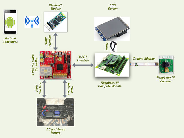
The hardware design for VisionCar involves using a SJOne board, Raspberry Pi Compute Module and Bluetooth Transciever as described in detail in the following sections. Information about the pins used for the interfacing of the boards and their power sources are provided.
System Architecture
The hardware design for VisionCar involves using a SJOne board, Raspberry Pi Compute Module and Bluetooth Transciever as described in detail in the following sections. Information about the pins used for the interfacing of the boards and their power sources are provided.
Power Distribution Unit
Power distribution is one of the most important aspects in the development of such an embedded system. VisionCar has 6 individual modules that require power supplies of various ranges for its operation as shown in the table below.
| Module | Voltage |
|---|---|
| SJOne Board | 3.3V |
| Raspberry Pi Compute Module | 5.0V |
| Servo Motor | 3.3V |
| DC Motor | 7.0V |
| Bluetooth Module | 3.6V - 6V |
| LCD Display | 5.0V |
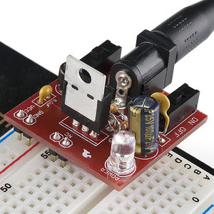
As most of the voltage requirements lies between 3.3V to 5V range we made use of SparkFun Breadboard Power supply (PRT 00114). It is a simple breadboard power supply kit that takes power from a DC input and outputs a selectable 5V or 3.3V regulated voltage. In this project, the Input to the PRT 00114 is provided by a 7V DC LiPo rechargeable battery.
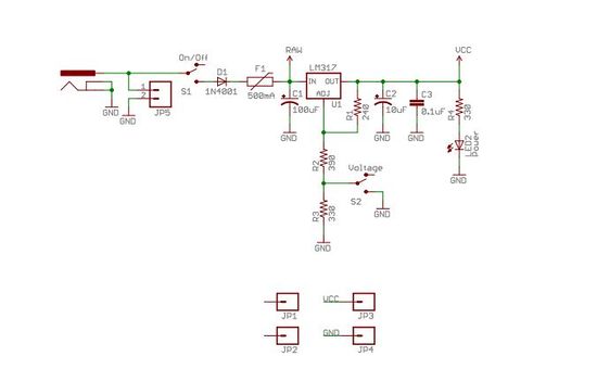
The schematic of the power supply design is as shown in the diagram below. It has a switch to configure the output voltage to either 3.3V or 5V.
For components requiring a 7V supply, a direct connection was provided from the battery. Additionally, suitable power banks were used to power these modules as and when required.
Car Controller
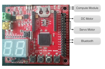
The car controller, in our case is the SJOne board and is connected to the bluetooth, compute module, servo and DC motors. The pins used are as shown below. The connections are all done through the connection matrix.
| Pin | Connection |
|---|---|
| P2.0 | DC Motor PWM |
| P2.1 | Servo Motor PWM |
| TXD2 | To RXD of Bluetooth Module |
| RXD2 | To TXD of Bluetooth Module |
| TDX3 | To RXD of Compute Module |
| RXD3 | To TXD of Compute Module |
Connection Matrix
This is a general purpose PCB which is used to mount the external wiring used in our system. The prototype PCB board houses the
- Power Supply (PRT-00114)
- Vcc and Ground signals.
- PWM control signals.
- UART interconnections.
- Bluetooth module’s interconnections.
It is an essential component of our design, as it makes it easier to connect different modules together.
Motor Interface
VisionCar uses a DC and Servomotor to move the car around. These motors were interfaced to the Car Controller using the pins as described below and were controlled using PWM signals.
Servo Motor Interface
The VisionCar has an inbuilt configurable servo motor which is driven by PWM. The power required for the servo motor operation is provided the rechargeable LiPo battery. Servomotor requires three connections which are 'VCC', 'GND' and 'PWM’. The width of the PWM signal turns the servo across its allowed range of angles. The pin connections to the Car Controller are as shown in the table below.
| Pin | Connection |
|---|---|
| VCC | 5V |
| GND | Ground Connection |
| PWM | PWM Signal from P2.1 on SJOne |
A table with values of PWM signal required to drive the Servo Motor is also shown.
| Direction | PWM Duty Cycle |
|---|---|
| LEFT | 9.0 |
| SLIGHT LEFT | 8.5 |
| STRAIGHT | 7.5 |
| SLIGHT RIGHT | 6.5 |
| RIGHT | 6.0 |
The Servo motor used in this project has an operating range of 5-10% which corresponds to complete left and right turn respectively. For our application, we make use of PWM duty cycle from 6.0 to 9.0 at 50Hz frequency.
DC Motor Interface
The RC Car comes installed with a DC Motor connected to an ESC unit. Controlling the DC Motor controls the speed of the car. We use PWM signals to drive the DC motor. The Motor draws power directly from the battery on the car. DC Motor pin connections as as shown in the table below.
| Pin | Connection |
|---|---|
| VCC | 7V |
| GND | Ground Connection |
| PWM | PWM Signal from P2.0 on SJOne |
DC Motor PWM operating range is from 5 - 10 % Duty cycle at 50Hz. We use the following settings to control the speed of the car.
| Speed | PWM Width |
|---|---|
| REVERSE | 7.00 |
| STOP | 7.48 |
| MEDIUM | 7.80 |
| FAST | 7.90 |
Bluetooth Interface
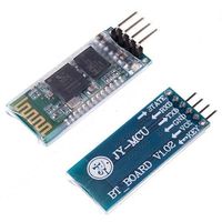
The car is controlled through a customized mobile application which uses HC-06 controller (bluetooth interface) which is then connected over to the SJOne board (development board) over a UART communication.
This controller receives the control signals from the mobile application and passes the information in a byte level format over to the development board.
The HC-06 controller has 4 external pins which are VCC (power), GND (ground), TXD (Transmit over UART) and RXD (Receive over UART) which are currently used in our application -
| Pin | Connection |
|---|---|
| VCC | 3.3V from Power Supply Unit |
| GND | Ground Connection |
| TXD | RXD2 from SJOne board |
| RXD | TXD2 from SJOne board |
Image Sensor - Raspberry Pi Compute Module
Features and Specifications
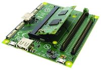
The compute module contains a BCM2835 processor, 512 MB RAM and 4GB EMMC Flash. This is integrated to the Compute Module IO board which fits into a standard DDR-2 SODIMM connector.
The compute module IO board has two onboard camera interfaces and comes with an adapter for Raspberry Pi Camera board. It has a HDMI output port which can be connected to a LCD display for viewing the image inputs and outputs. It exposes the GPIO pins of the processor. In total, the IO board has 120 GPIO ports grouped into 2 banks, each having 60 pins. It also has a USB port with USB 2.0 support.
Installation and Setup
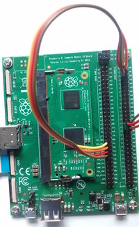
Pins 14 and 15 are connected to the UART0 RX and UART0 TX of BCM2835. These pins are used to communicate with the Car Controller.
CAM1 interface is used for connecting the camera and it requires the following pins to be connected using jumper wires for operation:
- Attach CD1_SDA (J6 pin 37) to GPIO0 (J5 pin 1)
- Attach CD1_SCL (J6 pin 39) to GPIO1 (J5 pin 3)
- Attach CAM1_IO1 (J6 pin 41) to GPIO2 (J5 pin 5)
- Attach CAM1_IO0 (J6 pin 43) to GPIO3 (J5 pin 7)
Software Design and Implementation
Design Flow
Tasks & Implementation
- Motor Control task
- Bluetooth task
- Heartbeat task
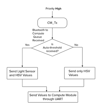
- CM_Tx task
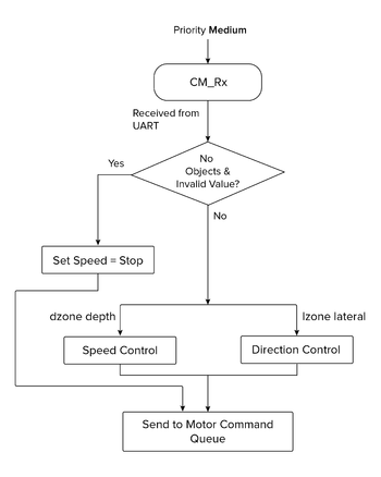
- CM_Rx task
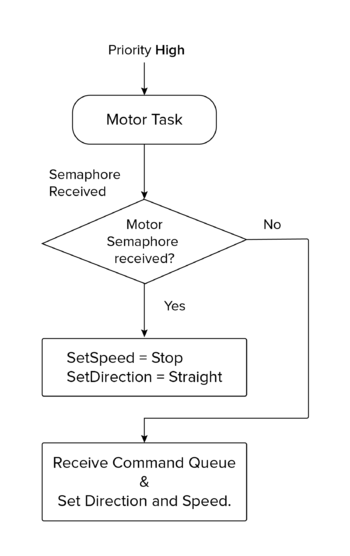
Motor Control Tasks
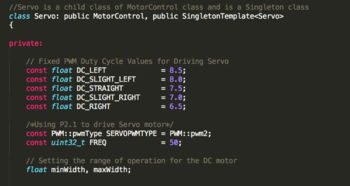
We made use of the Singleton Instance of the PWM2 on the SJOne board. To initialize the PWM object we need to set the Pin number to be used along with the frequency of operation. Below is a screenshot of the code which has the pwm configuration information for the servo motor:
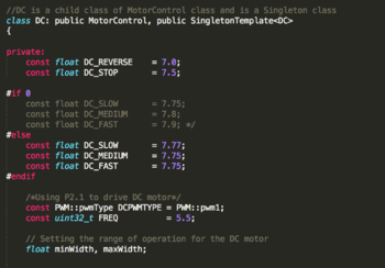
We made use of the Singleton Instance of the PWM1 (P2.0) on the SJOne board. To initialize the PWM object we need to set the Pin number to be used along with the frequency of operation. Below is a screenshot of the code which has the pwm configuration information for the DC motor:
Bluetooth Task
This is a separate task implemented for receiving the signals from mobile application which is used in turn to control the car.
It has been designed primarily to decode the message signal sent across bluetooth over a UART communication channel and use it to send control information to appropriate tasks which are used for different modes to control the car.
It has been designed sleep until it receives any message over UART (transmitted through bluetooth ). Once the message is received, task does appropriate actions which is explained below.
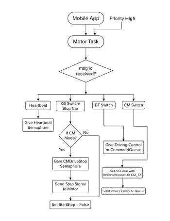
This task has different sections which sends control signals to appropriate tasks based on the message ID received-
- Heartbeat Task
When the bluetooth task receives a heartbeat task message ID, it sends a signal using a semaphore over to the heartbeat task.
- Kill Switch
When a kill switch message is received it switches off every operation which runs the car motor control and issues a stop signal to the motor control task to stop the car.
- Compute Module task switch
When a compute module task switch message is received , the car will now start receiving driving controls messages from compute module task (CM_Tx and CM_Rx). Bluetooth task cannot drive the car from this point onwards unless a bluetooth task switch is given.
- Bluetooth Module task switch
When a bluetooth module task is received , the car will start running based on the directions given by the mobile android app.
HeartBeat Task
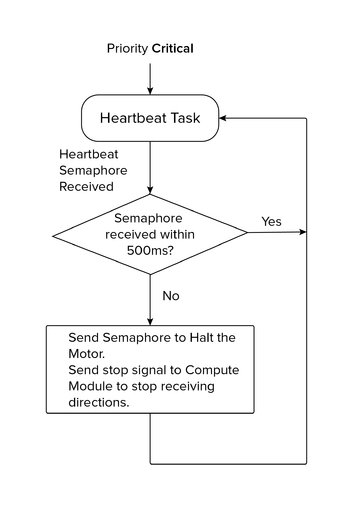
Heartbeat task is implemented as a safety mechanism to maintain the car within the control vicinity of the Bluetooth Device. The Heartbeat task is designed to receive a heartbeat signal from the mobile phone every 500ms. On the other hand, the android application in the mobile device is designed to send a character (heartbeat) for every 300ms. <Add ScreenShot of Heartbeat Task If the car fails to receive the heartbeat signal from the mobile device over a span of 500 of 500ms, the master controller stops the car immediately. This is implemented as an extra layer of precaution to monitor the movement of the car.
CM_Tx Task
CM_Tx is a task implemented to enable transmission of information from SJOne board to the Compute module over an UART available on the SJOne board. Usage of this task can be broadly classified into two main categories. Firstly, to transmit the threshold value for the image processing filter which is provided by the Android application running on the mobile device. Next application is to send the current light sensor value of the surrounding environment.
Threshold value selection: The image processing algorithm which is implemented on the compute module requires threshold values of Hue, Saturation and Value. And these threshold parameters vary for various objects. In order to provide our VisionCar with an ability to detect a wide variety of objects in real time, this feature of dynamic thresholding is implemented in the design. The android application has the control to modify the HSV threshold values and save them to a file. CM_Tx provides the API to receive the threshold over the bluetooth device and transmit to the Compute module over an UART.
Light Sensor Value: The threshold filter value for the same object varies in different lighting conditions. In order to compensate this effect, an Auto-threshold mote is provided in the design. When Auto-threshold mode is selected CM_Tx sends the current light sensor values from the SJOne board to the COmpute Module. Based on the light sensor values received the compute module selects the threshold values from a Lookup table which has the mapping of Light sensor readings to the corresponding threshold values.
CM_Rx Task
CM_Rx is the task implemented to receive the location information of the object in the frame. The Compute module tracks the object and provides the lateral zone and depth zone information to the Master controller. The master controller receives the information from the compute module over an UART and drive the motor accordingly which results in effectively tracking the vehicle. CM_Tx task is one of the most important tasks in master controller which receives location information and drive the car accordingly.
Driving Algorithm
Car motor control has been designed to operate from either bluetooth module mode or compute module mode.
Bluetooth module drives the car with control buttons setup in the customized android application. The android application has designed to switch between bluetooth and compute module mode. When the control is switched to compute module mode, the algorithm has been designed to start receiving values from compute module which in our case would be the imaging algorithm sending out driving signals to the SJOne board.
The bluetooth module provides direct mapping to the motor task to execute commands exactly as per bluetooth control signals.
The compute module unlike the bluetooth task sends the depth and lateral zone information which is in turn used for developing control signals to the motor task to drive the car.
The code below will explain action taken by the motor task based on the values sent by the compute module task -
   if( ( dzone == ZONE_NO_OBJ ) || ( lzone == ZONE_LATERAL_INVALID ) )
   {
       // Stop Car
       motorCmd.op = SPEED_ONLY;
       motorCmd.speed = STOP;
       return;
   }
   motorCmd.op = SPEED_STEER;
   switch(dzone)
   {
       case ZONE_FAR:
       case ZONE_MID_FAR:
       case ZONE_MID:
           // Speed to Slow
           motorCmd.speed = SLOW;
           break;
       case ZONE_MID_NEAR:
       case ZONE_NEAR:
       case ZONE_DEPTH_INVALID:
           motorCmd.speed = STOP;
           break;
   }
   switch(lzone)
   {
       case ZONE_CENTER:
           // Steer to Center
           motorCmd.steer = STRAIGHT;
           break;
       case ZONE_LEFT_N:
       case ZONE_LEFT_I:
           // Steer to Slight Left
           motorCmd.steer = SLIGHT_LEFT;
           break;
       case ZONE_LEFT_X:
           // Steer to Left
           motorCmd.steer = LEFT;
           break;
       case ZONE_RIGHT_N:
       case ZONE_RIGHT_I:
           // Steer to Slight Right
           motorCmd.steer = SLIGHT_RIGHT;
           break;
       case ZONE_RIGHT_X:
           // Steer to Right
           motorCmd.steer = RIGHT;
           break;
   }
Compute Module
Compute module provides a dual camera interface that is suitable for both mono and stereo vision based image processing. Combined with a HDMI display support, this makes it a suitable platform to prototype simple image based applications. The underlying architecture of the Raspberry Pi also has a VPU which can be used for relatively faster computations. The overall form factor of the platform and the camera board are also small and suitable for mounting on a RC car like the one used in this project.
The downside that we faced after selecting this platform was that there is not enough documentation or support to fully exploit the features of the compute module. As per available information online, using the VPU requires us to rewrite the imaging algorithms in assembly code. This task was not possible within the time frame that was available to implement this project. Moreover, we intended to use OpenCV support for building our applications. In the end, we had an OpenCV application running on a single-core CPU which was not responsive enough for a stereo based application. Our final implementation uses a single camera based object-tracking algorithm using OpenCV.
Platform Setup
Setting up the platform required building the necessary kernel and OS utilities, library packages, openCV library and the root file-system. We utilized the buildroot package to configure the software required by the platform. There were many dependencies that needed to be resolved to be able to finally bring up the board for OpenCV application development.
Buildroot provides the framework to download and cross-compile all the packages that are selected in the configuration file. Toolchain for the platform is also built on the host system by buildroot. We saved our buildroot configuration in a file named “compute_module_defconfig”.
Most of the board bring-up time was spent in enabling OpenCV support for the platform. There were many dependencies that were needed to be resolved. OpenCV requires the support of libraries such as Xorg Windowing System, GTK2 GUI library and openGL.
The basic steps to build a system software for compute module is given in the link below.
https://github.com/raspberrypi/tools/tree/master/usbboot
The first requirement is to build an application, “rpiboot”, that is used to flash the onboard eMMC flash of the compute module (Refer to the link above for steps to build the rpiboot application). This application program interacts with the bootloader that is already present in the compute module and registers the eMMC flash as a USB mass storage device on the host system. This way, we can copy programs and files to/from the file system already present on the target platform and also flash the entire eMMC if necessary.
Once we are able to interact with the eMMC flash onboard the compute module, we can build the required image using buildroot. Buildroot can be cloned from the repository below.
git.buildroot.net/buildroot
Run “make menuconfig” in the buildroot base directory to perform a menu driven configuration of the system software and supporting packages. After saving and exiting ‘menuconfig’, the saved configuration can be found in the file called “.config” in the base directory. Save this file under a desired name in “{BUILDROOT_BASE}/configs” directory. We saved ours as “compute_module_defconfig”. The next time we build using buildroot, we can just run “make compute_module_defconfig” to restore the saved configuration.
As stated above, we ran into dependency issues with respect to OpenCV support. We were faced with errors such as “GTK2: Unable to open display”, “Xinit failed”, etc. This link shown below was very helpful in resolving the issues.
https://agentoss.wordpress.com/2011/03/06/building-a-tiny-x-org-linux-system-using-buildroot
We were able to bring up “twm” or Tiny Window Manager on the platform and run some sample OpenCV applications.
The next task was to enable camera and display support on the compute module. By default, the camera is disabled and the HDMI interface is not configured to detect a hot-plug. We referred to the link shown below to enable HDMI hot-plug through the config.txt file in the boot partition.
https://www.raspberrypi.org/documentation/configuration/config-txt.md
The difficulty in getting the camera to work was that a large amount of documentation online pointed at installing "raspbian" OS on the pi and running apt-get or other rpi applications to enable the camera interface. The existing raspbian image does not fit into the compute module eMMC flash. The camera interfaces are disabled by default. To enable the same, config.txt requires 'start_x' variable to be set to '1'. This would cause the BCM bootloader to lookup a start_x.elf and fixup_x.dat to actually enable to camera interfaces. In brief, this would cause the loader to initialize the GPIOs, shown in hardware setup section, to function as camera pins. This step also requires a dtb-blob.bin, a compiled device tree, setting the necessary pin configurations. If this file is missing, the loader will use a default dtb-blob.bin built into the 'start.elf' ( Please note this is not the same as start_x.elf ) binary. We located this file by running “sudo wget http://goo.gl/lozvZB -O /boot/dt-blob.bin”. Once the CM boots up, executing “modprobe bcm2835-v4l2” on the module will load the v4l2 camera driver. OpenCV uses this driver to interact with the onboard camera interface.
Once the buildroot has produced the image, it needs to be flashed to the compute module eMMC. A step by step procedure for the same is given in the link below.
https://www.raspberrypi.org/documentation/hardware/computemodule/cm-emmc-flashing.md
Note that the jumper J4 position onboard needs to be changed for the CM to behave as a USB slave device.
Object Tracking using OpenCV
Tracking of an object is made possible by using image processing and image analysis techniques on a live video feed from a camera mounted on the VisionCar. Relying on images as the primary ‘sensing’ element allows us to act upon real objects in a very intuitive way – similar to how we humans do. We use OpenCV, an open source real time computer vision library to process live video frames. The library provides definitions of datatypes such as Matrices and methods to work on them. In addition, it provides optimized implementations for complex image processing routines. We have designed and implemented an application to perform object tracking using features provided by OpenCV library.
An image is a 2D array of pixels. In the case of a coloured image, each pixel is represented by 3 components - red, green and blue. Apart from the RGB color scheme, the HSV or Hue, Saturation and Value scheme is widely used in image processing. Separating the color component from the intensity can help in obtaining more information from an image.
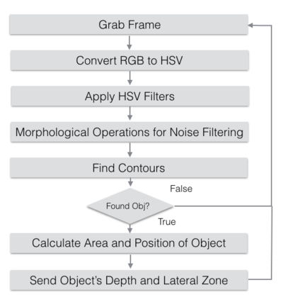
The algorithm for object tracking is as shown in Fig<>. The application performs tracking based on the color information of the object. On reading an image frame from the camera, we obtain an RGB frame. This is converted to HSV color format using the ‘cvtColor’ provided by OpenCV. A filter is applied to the resulting HSV frame based on which, we obtain a thresholded image. These values have to be configured per object that is to be tracked. The HSV frame is now subjected to morphological operations such as dilate and erode to filter noise, isolate individual elements and join disparate elements. This forms a perfectly segmented image with the target object in sight. Next, all the contours/shapes in the filtered image are determined using the findContours OpenCV function. This would return a list of contours and their sizes as per the contents in the filtered image. We use ‘moments’ to determine the area and location of the object. This information is also sent to the Car Controller through the Communication Interface. If the area of the object is not within the threshold specified, we consider the object to be absent. These sequence of operations are carried out continuously on every frame thereby tracking the target object.
The application was executed and tested on a desktop environment with a Webcam before porting it to compute module.
The flowchart for the object tracking application is given below.
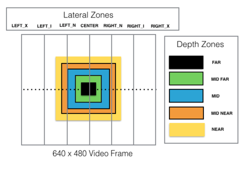
As mentioned, the object's area and position information is sent over to the car controller. The horizontal/lateral position of the target object in the frame is divided into multiple zones from extreme left to extreme right. The depth or distance to the object which is based on the area of the object in the frame is also divided into multiple zones from ‘near’ to ‘far’. These zones are depicted in the figure below. The thresholds for each of these zones are to be set based on the object to be tracked.
Communication Interface
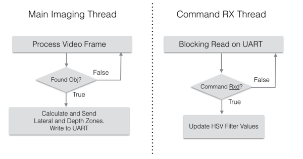
The communication interface of the Compute Module is just a simple UART. The CM receives data regarding HSV thresholding values and light sensor readings from the LPC module. The position and distance to the tracked object is sent by the CM back to the Car Controller. The application on the CM has two threads. One is the main image processing thread. The UART write is performed by this thread once per frame as and when the position of the target object is computed. The second thread performs the UART read to adjust the HSV threshold values. This thread performs blocking read calls and remains asleep as long as there is no data available from the LPC module. The data format which is transmitted/received in the CM is explained below.
The transmitted data is a simple 4 byte structure as shown below.
   typedef struct imgSensorInfo
   {
       imgSInfo	SyncByte;  // Sync Byte for image sensor value
       imgSInfo	LatZone;   // Lateral Zone
       imgSInfo	DepthZone; // Depth Zone
       imgSInfo	Reserved2; // Reserved Field
   } imgSensorInfo;
The object's depth and lateral zone information is encoded in the 'lZone' and ‘dZone’ field of the data structure. The possible values for the ‘lZone’ and ‘dZone’ in the form of enumerations is shown below.
   typedef enum objLatZones	// Lateral zone in which the object is located
   {
       ZONE_LEFT_X,		// Object is to the extreme left of the farme
       ZONE_LEFT_I,			// Object is to the intermediate left of the frame
       ZONE_LEFT_N,		// Object is to the near left of the frame
       ZONE_CENTER,		// Object is to the near left of the frame
       ZONE_RIGHT_N,		// Object is to the near right of the frame
       ZONE_RIGHT_I,		// Object is to the near right of the frame
       ZONE_RIGHT_X,		// Object is to the near right of the frame
       ZONE_LATERAL_INVALID
   } objLZones;
   typedef enum objDepthZones	// Depth zones in which object is located
   {
       ZONE_NO_OBJ,
       ZONE_FAR,
       ZONE_MID_FAR,
       ZONE_MID,
       ZONE_MID_NEAR,
       ZONE_NEAR,
       ZONE_DEPTH_INVALID
   } objDZones;
The data format received by the compute module is as below:
   typedef enum btCommand
   {
       COMMAND_LIGHT_SENSOR,
       COMMAND_THRESHOLD_FILTER,
       COMMAND_END
   } btCommand;
   typedef struct btData
   {
       uint8_t command;
       uint8_t lightSensor;
       uint8_t threshData;
       uint8_t Reserved1;
   } btData;
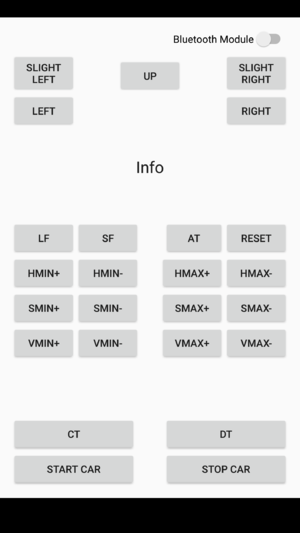
The values for the field ‘<command>’ is enumerated below. This value is sent from the bluetooth interfaced to the LPC controller. Each command increments or decrements its corresponding Hue, Saturation or Value thresholds. The “StoreFIle” command stores the current threshold values to a file. The “LoadFile” command restores the threshold values from the file.
   typedef enum objThreshModifier
   {
       CMD_HMIN_INCR ='q',
       CMD_HMIN_DECR ='a',
       CMD_HMAX_INCR ='w',
       CMD_HMAX_DECR ='s',
       CMD_SMIN_INCR ='e',
       CMD_SMIN_DECR ='d',
       CMD_SMAX_INCR ='r',
       CMD_SMAX_DECR ='f',
       CMD_VMIN_INCR ='t',
       CMD_VMIN_DECR ='g',
       CMD_VMAX_INCR ='y',
       CMD_VMAX_DECR ='h',
       CMD_LOAD_FILTER_VALUES = 'l',
       CMD_STORE_FILTER_VALUES = 'k',
       CMD_RESET_FITLER ='v',
       CMD_NOP
   } objThreshMod;
The flowchart for the UART communication control is shown below
Flaws of Current Algorithm
The current algorithm has its own set of disadvantages. The first disadvantage is that the algorithm relies on area to compute distance to the target object. Any small amount of noise can easily mislead the algorithm to track some source of noise in the image. A partial solution to this problem could be to utilize the light sensor readings and modify the threshold values to eliminate noise under varying lighting conditions. This might still be insufficient as the object itself may move from one lighting condition to another.
Stereo vision can add depth as an extra dimension for thresholding the image. Noise can easily be eliminated by using distance as a threshold value. But this requires good computation power which is not available in the current platform.
Android Application
Motivation
The reasons for building an Android app are manyfold -
- The Raspberry Pi Compute module, that is being used to perform the imaging, has a single USB port on board. Constantly having to connect a keyboard and a mouse to program on the platform, while copying source files to and fro from a pen drive, is a cumbersome process, which can be negated by outsourcing a part of the functionality to an Android application.
- Since the project makes use of a RC Car that is capable of traveling at 35 miles/hr, it seemed prudent to design a kill-switch mechanism that would ensure the Car’s safety in the event of it going out of user control. The Android app effectively acts a Heartbeat for the vehicle, ensuring that the vehicle is switched off once a heartbeat is missed. There can be various reasons for a heartbeat miss: the Car could have traveled out of reach of the Bluetooth module and is incapable of receiving any messages from the user and thus misses a heartbeat. Or the app on the phone could have crashed for reasons unknown. For the situations described, it would be wise to disable the car to avoid any damage and the android app enables that.
- In order to segment the target object from the background, it is necessary for us to modify the hue, saturation and intensity threshold values. Using an app to wirelessly set these values is less cumbersome than having to connect a keyboard to make modifications.
- By configuring the Controller on the Car to connect wirelessly over Bluetooth, we are building a framework for the future, where it would be possible to connect the vehicle to other smart objects. Using Android as the platform was a natural choice as the API is very well documented and its global presence is unparalleled.
Design
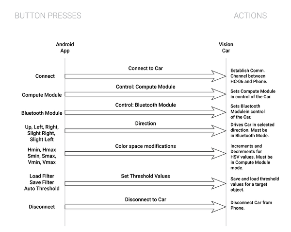
The Vehicle at a given time, is receiving commands from either the bluetooth module or from the compute module. It would thus make sense for the app to provide the user an option to select from between a “compute module” mode and a “bluetooth mode”. Our next steps would involve determining the user choices between the two different modes. Apart from providing the user with options to connect/disconnect to the HC-06 Module, the user is provided with options to drive the car in a direction. The app thus incorporates buttons to drive the car in directions defined by the motor control task. In Compute Module mode, there is no need for the user to input directions, as the car uses the Pi Camera to recognize the target object and traverse towards it. In this mode, buttons have been added to modify the Hue, Saturation and Intensity values so that the object can be separated from the background. The process of object detection can be observed on the LCD screen which is connected to a compute module via HDMI.
The bluetooth app also constantly sends a heartbeat message on a separate thread at specific intervals to ensure that the channel exists between the HC-06 module and the phone. This is precautionary in nature. If the Car were to unknowingly drift away from the control of the user, this thread ensures that the car stops once it is out of the range of the Phone.
Implementation
An Android app consists of two parts - a front end user-interface that defines the User Interface and a back-end that defines the logic for UI elements. The UI for the app is written in XML (Extended Markup Language) in a syntax that is reminiscent of HTML. The backend is written in Java, and makes use of the Android studio SDK to build the app.
The App uses the Bluetooth API to create a channel between the phone and the HC- 06 module. The Bluetooth API at the Android Developer page gives a fair idea of the steps involved in using the phone’s bluetooth to create a channel. The backend ties common bluetooth methods such as connecting, disconnecting and communication to the buttons defined in the UI. This is done by defining the behavior of every individual UI element present in the xml file.
The App makes use of a thread that uses a Blocking Queue to queue direction and HSV modifiers to be sent to the HC-06 bluetooth sensor. The logic to distinguish between commands directed to the bluetooth module and the compute module has been implemented in the Bluetooth task. Another thread constantly sends a message that has been designated as the heartbeat message between the motor control and the app. If the Car controller is unable to sync up with the heartbeat message, then the miss will essentially trigger a shut-down of the system.
Integration & Testing
This section explains the various stages of testing involved during the design and development of our Vision Car. We can broadly classify this process into five stages which are explained below:
Motor API
PWM based motor driver was our first and foremost implementation in terms of software. Once the design and coding of Motor API was completed, a test framework was developed to test the working of both the Servo and DC motor. The framework was designed in such a way to test the overall functionality of the Motor API. The framework also made sure that the PWM input always remained within the safe range, at the same it also assured that both the motors functioned as designed.
   CMD_HANDLER_FUNC(motorHandler)
   {
   motorCommand_t cmd;
   printf("Testing\n");
   if(cmdParams.beginsWithIgnoreCase("st"))
   {
       printf("Here\n");
       if(cmdParams ==  "st straight")
       {
           cmd.steer = STRAIGHT;
       }
       else if(cmdParams ==  "st left")
       {
           cmd.steer = LEFT;
       }
       else if(cmdParams ==  "st right")
       {
           cmd.steer = RIGHT;
       }
       else if(cmdParams ==  "st s_left")
       {
           cmd.steer = SLIGHT_LEFT;
       }
       else if(cmdParams ==  "st s_right")
       {
           cmd.steer = SLIGHT_RIGHT;
       }
       cmd.speed = STOP;
       cmd.op = STEER_ONLY;
       xQueueSend(motorTask::commandQueue, &cmd, 0);
   }
   else if(cmdParams.beginsWithIgnoreCase("sp"))
   {
       if(cmdParams ==  "sp stop")
       {
           cmd.speed = STOP;
       }
       else if(cmdParams == "sp slow")
       {
           cmd.speed = SLOW;
       }
       else if(cmdParams == "sp medium")
       {
           cmd.speed = MEDIUM;
       }
       else if(cmdParams == "sp fast")
       {
           cmd.speed = FAST;
       }
       else if(cmdParams == "sp abs")
       {
           cmd.speed = REVSTOP;
       }
       cmd.steer = STRAIGHT;
       cmd.op = SPEED_ONLY;
       xQueueSend(motorTask::commandQueue, &cmd, 0);
   }
   else if(cmdParams == "demo")
   {
       cmd.op = SPEED_STEER;
       for(int i = STOP ; i<SPEED_END; i++)
       {
           cmd.speed = i;
           for(int j = STRAIGHT ; j< STEER_END; j++)
           {
               cmd.steer = j;
               xQueueSend(motorTask::commandQueue, &cmd, 0);
               vTaskDelayMs(2000);
           }
       }
       cmd.speed = STOP;
       cmd.steer = STRAIGHT;
       xQueueSend(motorTask::commandQueue, &cmd, 0);
       printf("Demo Done\n");
   }
   return true;
   }
Bluetooth Interface
An android application built on the mobile device is the primary source of control of our Vision Car. Bluetooth interface also houses important features like KillSwitch, HeartBeat etc,. Once the Android application was developed, the bluetooth module which was connected to the SJOne board was paired with the mobile device to test the functionalities as listed below:
- Motor control signals
- Kill Switch implementation
- HeartBeat implementation
- Start and Stop State of the Vision Car.
Imaging Algorithm
Before using the compute module for image processing, the algorithms were tested on the local PC using a webcam. Various algorithms were provided as the part of OpenCV library, which was tested to suit our purpose. Finally few of the algorithms were selected and merged to fit our requirements.
Image Processing on Compute Module
After the image processing algorithm was tested on the PC using a webcam, it was ported to Compute Module which made use of Raspberry Pi Camera. Algorithm was tested for various objects in different lighting conditions. Based on trial and error method, various threshold values like HSV components and object area were finalized.
Integration testing
All the individual modules were integrated on our Vision Car and tested in the outdoor environment using the same objects used for testing in the simulated environment. Also testing was performed under different lighting conditions and backgrounds. It was also important to test the communication between individual modules which happened seamlessly.
Conclusion
To conclude, we were able to track a given target object using a single camera image processing although with some limitations. We already discussed the flaws of the imaging algorithm in section 5.2.4.4 and what better approach can be adopted for this purpose. We learnt a great deal about board bring-up, kernel customization, customizing OS, porting and cross compilation while setting up the platform. We also looked at isolating and identifying target objects and some of its characteristics in an image frame which we hope will be useful for us in the future. We also looked at multi-tasking and its associated issues like synchronisation between tasks, task priorities and their impact, etc. Overall, we had a great learning experience undertaking an image processing based project.
Project Video
Project Source Code
References
https://www.raspberrypi.org/documentation/hardware/computemodule/
https://www.youtube.com/watch?v=bSeFrPrqZ2A
https://agentoss.wordpress.com/2011/03/06/building-a-tiny-x-org-linux-system-using-buildroot/
https://www.raspberrypi.org/documentation/hardware/computemodule/cmio-camera.md
https://www.raspberrypi.org/documentation/configuration/config-txt.md
Android Source code repository from TopGun
Acknowledgement
We would like to acknowledge the guidance and efforts of Professor Preetpal Kang. This project was an undertaking in his course CMPE244, Spring 2016.
