S15: Touch Navigator
Contents
- 1 Touch Navigator
- 1.1 Abstract
- 1.2 Objectives & Introduction
- 1.3 Schedule
- 1.4 Part List
- 1.5 Design & Implementation
- 1.6 Testing & Technical Challenges
- 1.7 Conclusion
- 1.8 References
Abstract
The purpose of this project is to implement a robot car which will follow the path drawn on the touch screen.
Objectives & Introduction
- The prime objective of this project is to traverse a robotic car autonomously through specific map or grid depending upon the points drawn on the touchscreen.
- SJ-ONE board is used for two purposes, give control signals to motor driver IC and communication between user interface and car. Furthermore, communication between 2 boards is implemented by Embedded baseband wireless protocol using a on-board NORDIC wireless chip .Obstacle sensors are used to detect obstacles and avoid collision.
- Focus of project was to make an Real-time system/application using touchscreen and SJ-ONE development board which could guide and navigate a vehicle through a specific or predefined area.
Team Members & Responsibilities
- Athavan Kanagasabapathy
- Hardware Design/Interfacing,software for wireless communication.
- James Sushanth Anandraj
- Interface android phone with sender using UART over USB. Android Application design, Design of web interface.
- Ravikumar Vanjara
- Hardware Design/Interfacing,software for wireless communication.
- Rishit Borad
- Application Design ,Algorithm to calculate angle between source and destination.
Schedule
| Week | Start Date | End Date | Task | Status | Actual Completion Date |
|---|---|---|---|---|---|
| 1 | 4/7/2015 | 4/21/2015 | Developing Android Application to communicate to SJOne board over UART | Completed Successfully | 4/19/2015 |
| 2 | 4/14/2015 | 4/21/2015 | Interfacing the motor with the SJOne and controlling the direction and speed. | Completed Successfully | 4/21/2015 |
| 3 | 4/21/2015 | 4/28/2015 | Writing application in android to draw paths. | Completed Successfully | 4/30/2015 |
| 4 | 5/09/2015 | 5/11/2015 | Interfacing with the obstruction sensors. | Completed Successfully | 5/11/2015 |
| 5 | 5/4/2015 | 5/18/2015 | Mapping traversal area/co-ordinates on the android application. | Completed Successfully | 5/19/2015 |
| 6 | 5/16/2015 | 5/18/2015 | Integrating the Obstruction detection in main application. | Completed Successfully | 5/18/2015 |
| 7 | 5/18/2015 | 5/22/2015 | Testing | Completed Successfully | 5/24/2015 |
Part List
| Sr.No. | Parts | Cost | Useful part links/Datasheets |
|---|---|---|---|
| 1 | Dual H-Bridge Motor Driver for DC Motor L293D | 2.5 $ | ST microelectronics Datasheet |
| 2 | Car chassis parts - Wheels, shaft, DC motors(2), body | 12.0 $ | RC Car |
| 3 | Batteries/ Power source | 5.0 $ | Power Bank |
| 4 | IR Leds and IR sensor (TSOP38238) | 10.0 $ | IR sensor Datasheet |
| 5 | Antennas for Nordic communication | 4.0 $ | Router antennas |
Design & Implementation
Hardware Design
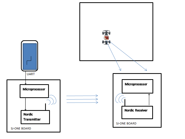
Block Diagram
Hardware Interface
- SJone Board
The SJ-One Board consists of LPC1758 microcontroller which belongs to the family of ARM Cortex-M3. It operates upto 100MHz clock frequency. ARM Cortex-M3 has a built-in Nested Vectored Interrupt Controller(NVIC) which can support 35 vectored interrupts. It has 512 KB of on-chip flash memory,64Kb on-chip SRAM. The SJ-One board also has a built-in Nordic Wirless device embed on it namely "nRF24L01P", which is used as wireless communication from one board to another board. The board has many accelerated GPIO pins and each of the port pins can be controlled as I/O individually.
- Nordic wireless
The nRF24L01P is a single chip 2.4GHz transceiver with an embedded baseband protocol engine (Enhanced ShockBurst™), suitable for ultra low power wireless applications. This Nordic wireless device operates at the ISM frequency at the range 2.4 to 2.4835GHz. The design interface between the Nordic wireless device and SJ-One board was established through a Serial Peripheral Interface (SPI) bus. The register map, which is available through the SPI, contains all setup enrolls in the nRF24L01+ and is open in all operation methods of the chip. The wirless communication done by packet-based messgae communication. Internal FIFOs ensure a smooth data flow between the radio front end and the system’s MCU. The radio front end uses GFSK modulation. It has user configurable parameters like frequency channel, output power and air data rate. nRF24L01+ supports an air data rate of 250 kbps, 1 Mbps and 2Mbps. The two power saving modes make the nRF24L01+ very suitable for ultra low power designs.
- Motor driver
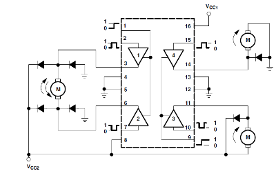
The L293D are quadruple high-current half-H bridge drivers. The L293D is designed to provide bidirectional drive currents of up to 600-mA at voltages from 4.5 V to 36 V. The internal block diagram of L293D is shown as below,
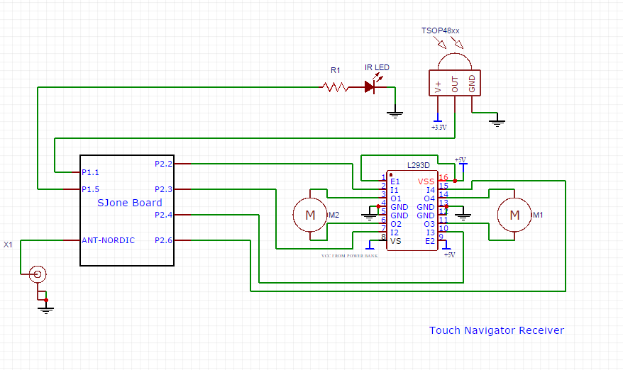
In this project, we are using two DC motors at the front and backend of the car in order to control the direction and forward/backward movement respectively. All inputs of the IC is TTL compatible. As in the block diagram there are 4 internal drivers. The drivers 1 and 2 are used for controlling the movement of the car and are enabled by Pin 1. The drivers 3 and 4 are utilized for another motor which controls the direction of the car and are enabled by Pin 9.
- FT232
The FT232 is a USB to Serial UART interface. It provides a single chip USB to Serial data transfer interface.Since USB is the most commonly available communication port on many modern devices. This chip allows us to interface LPC1758 with our Android device. We were able to obtain jar files that support common functions like open,connect, config, read , write and close.
Schematics
Software Design
Generating Car Control Commands from Touch Data
To generate the car control commands for TouchNavigator, we are using JS as an UI of our Android device. TouchEvents API is used to get the track of user activity on our android device. We are taking co-ordinates after user picks up his finger from the android device (action.up event). Co-ordinates are then formulated to generate meaningful data i.e commands for the TouchNavigator as our TouchNavigator understands only pre-defined commands to move on predetermined path.
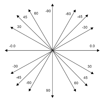
For TouchNavigator to go to next point it is required to get the angle and the distance between current point and next point. For angle we are using atan() function and for distance we are using cartesian distance between two points. Challenge in using atan() is it is giving angles between two points as per Fig: Arctan given below.
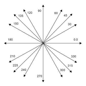
This is not so much useful for our TouchNavigator as angles understood by TouchNavigator are discrete. To generate a correct command, angles needed to be clear to understand. As a resolution to this problem we are mapping angles generated by atan() to a circle(Fig. Mapped Arctan).
It is not enough to generate angles between two points as every time it generates an angle referring Fig. Mapped Arctan. In other words, for example in a 4 quadrant map, we are calculating an angle between point(0,0) and (0,1) we get 90 degree and then from (0,1) to (-1,2) we get 135 degree. But the displacement from current orientation to next orientation is 45 degree on left side. So we are calculating displacement in orientation so that TouchNavigator does not go back to its default orientation and come back again at next orientation. Here default orientation is 90 degree. We are also limiting the turning angle to 179 degree, for more then 179 degree angle it calculates the smaller angle which is in range of 0-179 degree. Based on process mentioned above we are generating below commands
      1) m f : move forward.
      2) m l 30: move left by 30 degree.
      3) m r 45: move right by 45 degree.
      etc.
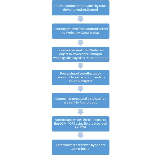
Information processing stages
The flow of information from the touchscreen to the transmitter LPC1768 is detailed below
Transmitter and Receiver Synchronization
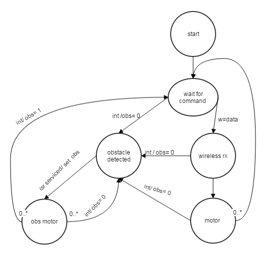
Once the commands for the path are received by the transmitter, they are stored in a queue. Another task dequeues them and sends them wirelessly at regular intervals. If the car detects an obstacle, while executing the previous commands, it responds back to the transmitter with a special code. Once the special code is received, the transmitter stops sending further commands until the obstacle ISR is serviced. Once it is finishes servicing it sends back again special code back to transmitter to resume sending further commands. Thus we have implemented real time obstacle detection and avoidance.
Implementation
State Machine
Android Application
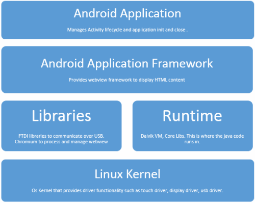
The android application was developed with Android SDK on Android IDE. The application is designed to run on any android device that supports API 17 and above. For the android application to successfully communicate with LPC1768 the device on which the app is running must support USB Host mode. The android application consists of 3 parts.
- FTDI library
- Fragment Layout activity
- HTML and Javascript frontend
FTDI Library
The FTDI library is a jar file and is provided by the manufacturer. This jar contains the code to open, connect, config, send and write data when connected to LPC1768 using UART via USB. No changes were needed for this library to be used in our project. After reading the documentation for the API , if the API are called in a proper sequence. Data can be exchanged between LPC1758 and the android device.
Fragment Layout Activity
The fragment layout activity handles the activity lifecycle of the android app. It loads the appropriate UI view based on the state of the application. In our activity the view consists of a Webview. The Webview is load a webpage and display its contents on UI. The webview component allows for dynamic content to be generated and displayed by running the javascript ceode defined in the webpage. The webview component also allows touchscreen events to propagate to the javascript layer where they can be handled. Another important feature of the webview component is that it provides a two way interface between javascript and android app. The first interface allows functions defined in android to be called from the javascript code running on the webpage.This is used to send processed commands to android app from javascript. The second interface allows android to call functions in javascript. This is used to send data read from the COM port to the javascript.
HTML and Javascript FrontEnd
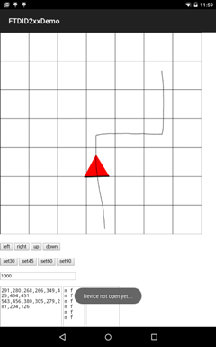
This is the crux of our application. In this code we generate UI Frames for every fixed interval and update the screen UI. The screen ui consists of a grid that represents the area where the car navigates in. Every frame we display the current location and orientation of the car. Once the user draw a path on the screen. We capture the coordinates touched on the screen and use the algorithm described above to calculate the commands and future orientations of the car. Once this data is generated. We issue the commands and update the position and orientation of the car at regular intervals of time. When the user provides a new path. The process is repeated to update the UI and issue corresponding commands.
The software stack representation of our android app is as follows.
Testing & Technical Challenges
- Mapping generated angles into meaningful data and deriving perfect mean angle at which car should turn next.
- Creating an android application using FTDI library to communicate with the sender LPC17XX board.
- Managing the UI animation and determining time interval to update UI and send the commands.
- IR sensors are detecting obstacles from a particular distance but in case of obstacle occurring suddenly in the way of TouchNavigator it could not detect the obstacle as quickly and crashes in to it. To overcome this challenge we are using interrupt for IR sensor to handle obstacle avoidance.
- Turning angles are dependent on the momentum of the angle, even the smaller degree of angle with high momentum causes car turning shapely. As a resolution of the problem, Instead of directly processing the received data from the wireless we are making a queue and storing the received data, and then giving data to controller one-by-one as it moves further. In other words we are handling momentum of the car by giving it data from the queue.
- Power Source: Using a AA/ni-cad battery without a constant voltage constant current supply causes difference in current sourced to motors as it discharges. This in turn causes variation in turning angles of motor i.e not a constant turning angle. As a remedy of this we used a 2200mAh 5V constant voltage constant current power bank which we generally use to charge our cellphones.
Conclusion
We are able to navigate the car successfully on path given in an android application. It was a great learning experience in embedded systems. We learned implementation of Real Time Operating System along with semaphores, queues and task priority mechanism. As we had to try different communication methods to get efficient and cost effective solution, we got a chance to learn and implement NORDIC wireless communication. This project also helped us understanding interfacing of an android device with a development board.
Project Video
Upload a video of your project and post the link here.
Project Source Code
References
Acknowledgement
We are grateful to our professor Preet Pal Kang for sharing his knowledge and wisdom throughout the semester and motivating us into successful implementation of this project. We also thank him for designing course CMPE 244 perfectly which helped us learn FreeRTOS & Semaphores and introducing us to many of the industry experiences and DO's and DONT's . We also like to express our gratitude to ISA-instructor Dhawal Parikh for guiding us from the selection of ideal project through the completion of the project.
References Used
- LPC1758_UserManual.pdf
- SJOne_lpc1758_rev4.pdf
- http://people.ece.cornell.edu/land/courses/ece4760/FinalProjects/f2014/mrr222_va86_dar324/4760%20Final%20Page/home.html
- http://www.socialledge.com/sjsu/index.php?title=SJ_One_Board#Board_Block_Diagrams
- http://www.ftdichip.com/FTDrivers.htm
- https://forelectronics.wordpress.com/2014/05/09/tsop-based-ir-sensor/
