S15: Smart Sparta Parking System
Contents
- 1 Abstract
- 2 Objectives & Introduction
- 3 Team Members & Responsibilities
- 4 Project Schedule
- 5 Parts List & Cost
- 6 System Block Diagram
- 7 Design & Implementation
- 8 Testing & Technical Challenges
- 9 Conclusion
- 10 References
Abstract
A smart parking system will aid people to find a parking slot at a parking garage. The system will display the available parking slots in real time and will direct the driver to a specified location hence reducing the trouble to find in huge space. This employs a Bluetooth communication with control center and consumer via an android application.
Objectives & Introduction
This project aims to simplify the parking process in large parking spaces. Currently, when a car enters a parking lot, the information is provided at the entrance about the total empty spots available. No information regarding where the exact spot is provided. If the parking lot is a large one and the spots left are very few, the users face a difficult time finding an empty spot.
What we are doing here is that we tell the user a spot number, based on his car size, where he can park his car. We also have provided the user with an android based mobile application which has a map of the parking lot hence making it easier for the user to find the exact location.
Team Members & Responsibilities
- Bhargava Leepeng Chandra
- Android application, Model/Prototype Design
- Gautam Saily
- Motor, Nordic Wireless, Model/Prototype Design
- Niveda Das
- IR Sensors, Nordic Wireless
- Rishabh Holenarasipur Sreedhara
- Display, LDRs, Integration
- Sujith Durgad
- Bluetooth, Control Centre
Project Schedule
| Week No. | Start Date | Planned End Date | Task | Status | Actual End Date |
|---|---|---|---|---|---|
| 1 | 03/30/2015 | 04/06/2015 |
* Design the Project Layout * Order necessary Hardware * Task allocation * GIT version control system setup and integration |
|
04/06/2015 |
| 2 | 04/06/2015 | 04/13/2015 |
* Start Model Implementation to position hardware * Design Android Application UI Layout * LCD base code testing * Research Nordic wireless |
|
04/13/2015 |
| 3 | 04/13/2015 | 04/20/2015 |
* Bring up parking layout and motors on to Model * Basic Bluetooth code testing * Basic Nordic wireless design |
|
04/21/2015 |
| 4 | 04/20/2015 | 04/27/2015 |
* Establish Communication between Nodes using Nordic wireless * Complete hardware model with Motors, IR sensors and LDRs installed * Implement IR sensors, LDRs and Motor (individual operation) * Update Wiki page |
|
04/27/2015 |
| 5 | 04/27/2015 | 05/04/2015 |
* LCD display Layout for information display with refresh * Implement Nordic wireless on all three boards * Verify multi-node communication * Android App basic initialization and interface with Bluetooth * Update Wiki page |
|
05/04/2015 |
| 6 | 05/04/2015 | 05/11/2015 |
* Integration testing with modular approach * Fixing issues * Update Wiki page |
|
05/11/2015 |
| 7 | 05/11/2015 | 05/18/2015 |
* Integration testing of complete system * Check if all systems are operational * Test working of system integration * Fixing issues * Update Wiki page |
|
05/18/2015 |
| 8 | 05/18/2015 | 05/25/2015 |
* Final testing * Complete Wiki page project report * Final demo |
|
05/24/2015 |
Parts List & Cost
| Index | Part Description | Part Number | Vendor | Qty. | Price/unit | Total Price |
|---|---|---|---|---|---|---|
| 1 | SJOne Board: ARM Cortex-M3 based LPC1758 Platform | Version 4 | SCE SJSU | 2 | $80.00 | $160.00 |
| 2 | Bluetooth Bee | B005GI4HFA | Amazon.com | 1 | $23.00 | $23.00 |
| 3 | LDRs | GM5539 | Amazon.com | 20 | $0.224 | $4.88 |
| 4 | IR Sensors | A382X5 | Amazon.com | 4 | $2.17 | $6.51 |
| 5 | Servo Motor | LS-0003 | Fry's Electronics | 2 | $9.99 | $21.73 |
| 6 | Model board | Cardboard sheet | Home Depot | 2 | $7.5 | $15.00 |
| 7 | Toy Car | Mustang GT, Lightning Mcqueen | Toysrus | 2 | $2 | $4 |
| 8 | MISC Components | -NA- | HSC, Anchor | -NA- | -NA- | $25.00 |
System Block Diagram
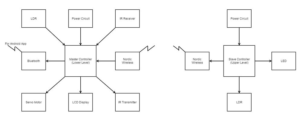
The left part of system block diagram consists of Master controller that is placed on the lower level. This is the master controller and it analyses the data received from LDR's of lower level and upper level through Nordic wireless, and based on the algorithm designed, it allocates a particular parking spot for the car. The right part of system block diagram consists of Slave controller that is placed on the upper level. This controller gathers the information from all the LDR's placed at every parking spot and transmits it to the master controller through Nordic wireless.
Every module is explained in detail in the following sections.
Design & Implementation
This section consists of the hardware/software design and implementation of our parking system model.
Master Controller
The master controller is the SJ-ONE board which is employed on the lower level of parking and it controls all the modules in the system. The functions of each module is explained below.
Slave Controller
The slave controller is the SJ-ONE board which is employed on the upper level of parking and it monitors the parking spots at the upper level using LDR and transmits the data to the master controller. The functions of each module is explained below.
Hardware & Software Design
The project reference model is divided into two parking levels. Both levels have different controllers. The lower level has the master controller and the upper level has the slave controllers. The modules controlled by the master are LCD Display, LED’s, LDR’s, IR Sensors, Servo Motors, Bluetooth Transceiver and Nordic Wireless. The modules controlled by slave controller are LDR’s and Nordic Wireless.
The function of each module is explained in the hardware implementation part.
Light Dependent Resistor (LDR)
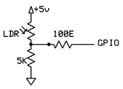
As the name suggests, LDR is a resistor whose resistance value depends on the light intensity. These LDR’s are used in our project at the following places:
- To detect the empty spots.
- To detect whether the car has crossed the boom-gate at the entrance and exit.
These LDR’s are placed at every parking spot in such a manner that if a car is parked over it, there will no no light reaching the LDR and hence the resistance will increase. This increased resistance is detected at GPIO inputs and the values at the GPIO pins (logic 0 - Presence of a car, logic 1 - absence of a car) are sent to the master controller.
LCD Display
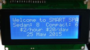
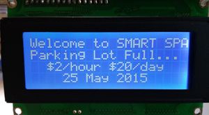
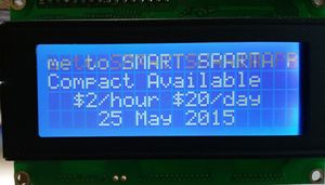
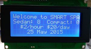
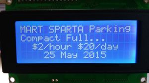
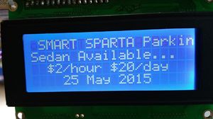
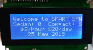
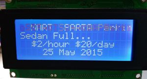
The LCD display is placed at the entrance of the parking lot. It displays one of the following:
- A welcome message with car park rates.
- The parking spot allocated to the car.
- A message saying that the parking lot is full.
Infra Red (IR) Sensors
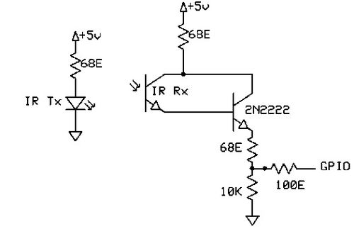
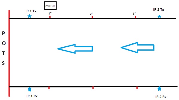
IR sensors are used to detect the presence of an object between the transmitter and the receiver. Output signal from the IR receiver depends whether the line of sight of the transmitter and receiver is intruded or not. In our project, IR sensor have been used to detect the presence of a car at the entrance and to measure the length of the car which further decides whether a compact or a big spot has to be assigned to the car. There are two IR sensors placed at the entrance. One is at the place where the car stops and other at an offset from the entrance (in our case it is 3.5 inches). When a car stops at the entrance of the parking lot, the first IR sensor is blocked. Then we check the second IR sensor. If the sensor is blocked the car is big in size, i.e. more than 3.5” long, otherwise it is a compact car.
Servo Motor
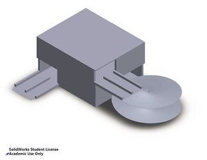
Servo motor is a geared motor that helps in the precise angular control. In our project, we are using the servo motor to control opening and closing of the boom-barrier (or boom-gate) at the entrance and exit. When a car is detected at the entrance by the IR sensor (assuming that the parking is not full) and the entrance button is pressed, the servo motor is actuated to turn 90 degrees so that the boom-gate is open. Once the car has crossed the LDR present at the other side of the boom-gate, the servo motor is brought back to 0 degrees and the boom-gate is closed.
Code snippet for Servo Motor
   PWM pwm4(PWM::pwm4, 50);
   while (1)
   {
       pwm4.set(5.0);
       printf("1 ms\n");//open
       delay_ms(1000);
       pwm4.set(10);
       printf("2 ms\n");//close
       delay_ms(1000);
   }
Bluetooth
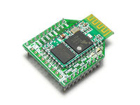
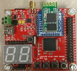
Bluetooth Bee is an easy to use Bluetooth Serial Port Profile(SPP) module compatible with existing Xbee sockets, designed for transparent wireless serial connection setup. Serial port Bluetooth module is fully qualified Bluetooth V2.0+EDR(Enhanced Data Rate) 3Mbps Modulation with complete 2.4GHz radio transceiver and baseband. It uses CSR Bluecore 04-External single chip Bluetooth system with CMOS technology and with AFH(Adaptive Frequency Hopping Feature). It has the smallest footprint of 12.7mm x 27mm. Default Baud rate:38400, Data bits:8, Stop bit:1, Parity:No parity, Start Bit:1 Supported baud rate: 9600,19200,38400,57600,115200,230400,460800.
Code snippet for Bluetooth:
     u3.init(115200);
     u3.put("\r\n+STWMOD=0\r\n");
     delay_ms(BT_DELAY);
     u3.put("\r\n+STNA=abcdefg\r\n");
     delay_ms(BT_DELAY);
     u3.put("\r\n+STOAUT=1\r\n");
     delay_ms(BT_DELAY);
     u3.put("\r\n+INQ=1\r\n");
     delay_ms(BT_DELAY);
Android Application
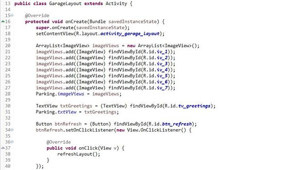
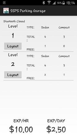
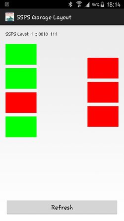
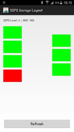
An application is developed for our Parking System that can work for Android Operating system. The application communicates with the SJOne development board over Bluetooth communication interface to display live information about the parking garage. The application is developed as two separate pages. The first page will display the relevant information that will have over all information about the parking garage that involves name of the garage, total number of slots, number of parking slots available, parking charges in terms of hour and day basis. The second page will display the model layout with parking slots designed based on the actual layout. The available slots will be displayed in green while the occupied slots will be in red. The following screenshots depicts the different aspects of the android appication.
Nordic Wireless
Nordic wireless supports multi-node mesh network with simultaneous communication between different nodes. It is a medium range wireless communication system which supports a fair amount of distance between different nodes. It is a low power application that extends the lifetime of a battery operated system. In our project we have used the nordic wireless to relay the sensor updates and other relevant information to the master controller at the lower level of the parking lot. The slave controller forms packets of the data it received from the LDR’s and transfers the information to the master controller wirelessly. To achieve this, we have to give a particular address to each node (master and slave) which is the base to operate a mesh network. We set the address of each controller by flashing the address in a file on each SJ-ONE board.
Hardware Interface
For two modules to communicate, there is a need of a protocol between them. This protocol is different for different types of interfaces. The communication between the different modules in our project is made possible due to the following hardware interfaces.
GPIO Interface
The GPIO pins on the SJ-ONE Board are used for switches, LED’s LDR’s and IR sensors. The GPIO pins are used as inputs for the IR receiver, LDR’s and switches. Whenever the signal at the output of these three devices is low, it indicates a logic ‘0’, and whenever the signal at the output of these devices is high, it indicates a logic ‘1’. The GPIO pins are used as outputs for LED’s and IR transmitter. Whenever the output signal is a logic ‘1’, 3.3V signal is given to the device and whenever the output signal is logic ‘0’, 0V signal is given to the device.
PWM Interface
The SJ-ONE Board on the lower level (Master controller) communicates with servo motor through PWM interface. In order to rotate the boom-gate at 90 degrees, PWM signal is sent to the servo motor.
Mesh Interface
The master controller (SJ_ONE Board) on the lower level communicates with the slave controller (SJ_ONE Board) on the upper level using a low mesh interface. The lower level receives the status of the parking spots acquired by the LDR’s at upper level using a mesh packet.
UART Interface
The master controller on the lower level communicates with the LCD display through UART interface. In order to display information on the LCD display, UART signals are transmitted to the LCD.
Hardware & Software Implementation
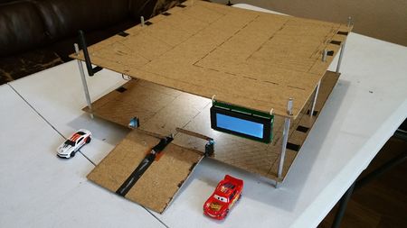
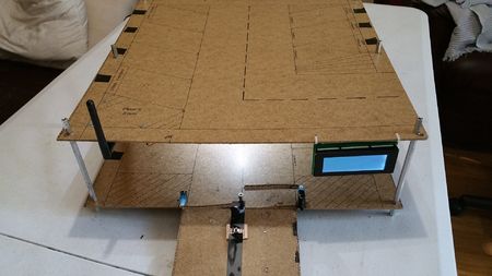
This section includes the overall working of the project. The physical model implementation of the parking garage in desplayed in the images below.
Back-End Algorithm
(Process of finding a parking spot)
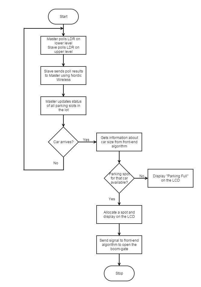
- The upper and lower module polls the GPIO pins connected to LDR’s to check the status of the spot (vacant or filled).
- This polling is done every one second. This means that the database is updated every second.
- As soon as the upper level controller polls the status of the LDR’s, it sends the packet containing the polling results to the lower level controller.
- This communication is done using Nordic Wireless.
- At this point , the back-end algorithm gets the information about the car size from the front-end algorithm and checks whether a parking spot is available for that particular car size.
- If a parking spot is available, its location will be decided here and displayed on the LCD.
- If there is no parking spot available, “Parking Full” message will be displayed on the LCD.
Front-End Algorithm
(What happens when a car arrives)
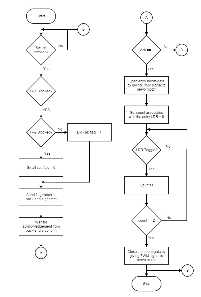
- The car comes at the parking lot entrance.
- The front IR sensor is blocked resulting in activation of the switch that has to be pressed to get a ticket.
- The second IR sensor (placed 3.5” from the boom-gate) detects the length of the car using the following steps.
- If the sensor is blocked, i.e. the car is greater than 3.5”. Hence it is categorized as a big car.
- If the sensor is not blocked, i.e. the car is less than 3.5”. Hence it is categorized as a compact car.
- This information about the car size is given to the back-end algorithm. If there is a free parking spot, the boom-gate opens.
- The LDR placed across the boom-gate checks whether the car has passed over it or not.
- When the car passes, the LDR gives the signal to the master controller to close the boom-gate.
Bluetooth Implementation
The system diagram to the riht shows the overall connection of the SJOne board and the Bluetooth bee module. This module can be mounted on the SJ one board on the zigbee base. The communication for configuration of the module is based on ST commands. There are unique commands for specific functions, to set the device name, set the pin, set the baud rate and much more. All you have to do is to save these ST commands in the form of string and send each byte serially to the module using a UART3. Initially the baud rate is set to 115200. Following table shows few of the AT commands which you may require.
Software Commands
| Commands | Use |
|---|---|
| \r\n+STWMOD=0\r\n | Set device working mode as client (slave). Save and Reset |
| \r\n+STBD=115200\r\n | Set baudrate 115200. Save and Rest |
| \r\n+STNA=Smart_parking_bluetooth\r\n | Set Device Name as "Smart_parking_bluetooth". Save and Reset |
| \r\n+STOAUT=1\r\n | Permit Paired device to connect me |
| \r\n+INQ=1\r\n | Commands for Normal Operation |
Android Application Implementation
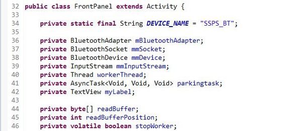
The Android application is developed in java programming language using the Android SDK embedded into Eclipse IDE. The aplication is given certain permissions in the android operating system to access the file system, bluetooth interface, WiFi (for future development of web server) etc. The source code for these startup permissions are briefly introduced in below. The implmentation flow is like in the decription.
- The application would access the Bluetooth Device of the Android device.
- It waits until the Bluetooth Bee on SJOne board is paired to the Android device (Named as SSPS_BT).
- Once the pairing is done, the application connects the Bluetooth Bee.
- After the connection is established successfully, the Bluetooth Bee sends a stream of data it receivces from the SJOne board using the UART3 communication interface in charaters to Android application.
- The andoid application receives the data stream and starts the analyses part. It analyses the character stream bit by bit in order to determine the status of each parking slot.
- After the analysis part is completed, the front UI is updated with these new values received from SJOne board that inturn gets it from the lDRs.
- Once the front panel is updated, the Layout UI for the two floors in the parking garage is populated with red/green colors based on the data.
- It shows that if the slot is green, that means it is available and if it is red, it means the slot is occupied.
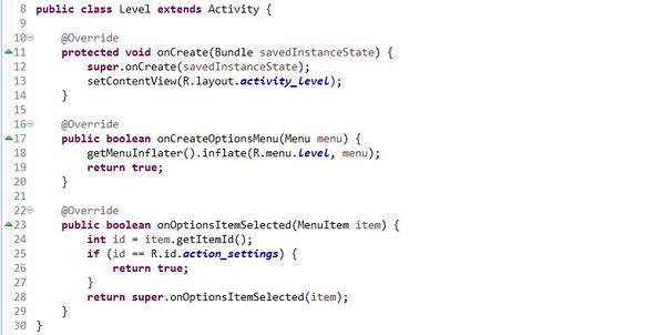
- The code snippets of the various aspects of the Application source code is shown below.
Code Snippet for Android Application
Screenshots of Application User Interface
IR Sensor Implementation
IR sensors are used at the entrance of the parking structure to determine the type of car, i.e whether the car is Compact (3 inch model) or Large (4 inch model). Two IR sensors are employed, IR1 and IR2 at a distance of 0.5 and 3.5 inches from the Stop sign. IR1 is used to check if the car has stopped and is in a position to press the switch used to replicate the parking ticket generator. Once the car stops at the entrance IR2 is used to find the type of car. If IR2 is blocked then the car is identified to be Large, else Compact car. The data from the two sensors are sent to the master board using GPIO pins.
Nordic Wireless Implementation
Each node, both the master and sensor (second board) is assigned with specific address called the node address. Once the car type is determined by the IR sensor’s, master board fetches the free slots info from the LDR’s interfaced to its itself and also from the sensor board at the top floor.
Master board requests for data through the following API:
- wireless_send(addr[noOfNodes], mesh_pkt_ack_app, &cmd, 1,hops))
The function sends the data packet to the particular node which is identified by the addr[noOfNodes] parameter. Upon receiving the data packet the node sends the acknowledgement back to the sending node which is stored in mesh_pkt_ack_app. The parameter hops give the distance between the two nodes.
The wireless_send() function sends the data packet and it returns true if the send is successful else it returns false indicating there was a failure in sending the packet. Assuming master sends the data packet to the slave successfully, it then waits for the slave to return back the packet with parking space info from the sensor node. The next step is to deform the packet the same way as it was formed. On deforming the packet, master gets the available slots for different car type.
Following are the rest of the API’s used at Master end are:
- wireless_get_ack_pkt(&pkt, 1000)
- wireless_deform_pkt(&pkt, 1, &freeLargeSlots, sizeof(freeLargeSlots), &freeSmallSlots, sizeof(freeSmallSlots));
The sensor node (board at the top floor) receives the request from master node, process the data, forms it into a packet and sends the formed packet to the master node.
The API’s used at the sensor node are:
- wireless_get_rx_pkt(&pkt,100)
The above function at the client side will wait for the request from the master node.
- wireless_is_ack_required(&pkt)
If the master has asked the sensor for acknowledgement then the above function would check for the same at sensor side.
- wireless_form_pkt(&pkt, pkt.nwk.src,mesh_pkt_ack_rsp,1,2,&freeLargeSlots,sizeof(freeLargeSlots),&freeSmallSlots, sizeof(freeSmallSlots))
The above function is responsible for forming the packet.
- wireless_send_formed_pkt(&pkt);
The above function is responsible for sending the formed packet to the master node.
Code Snippet for Nordic Wireless
Initialize and get Device address
   bool nordic_task::init()
   {
   myAddr = mesh_get_node_address();
   return true;
   }
Nordic wireless code snippet to Send data packets
   mesh_packet_t dataPac;
   uint8_t procNode = PROCESSING_TASK;
   uint8_t dataReq = lightValue;
   uint8_t lightSensor = 0;
   if (!wireless_send(procNode, mesh_pkt_ack, &dataReq, 1, 1))
   {
       LE.setAll(4); // If there is error sending the request packet all LEDs flash
   }
   else
   {
       LE.on(1); // Indicates the Request task has sent the packet
   }
   if (wireless_get_ack_pkt(&dataPac, 100))
   {
       if (!wireless_deform_pkt(&dataPac, 1, &lightSensor,
               sizeof(lightSensor)))
       {
           LE.setAll(4); // If there is error deforming the packet all LEDs flash
       }
       else
       {
           LE.on(3); // If packet is deformed successfully
       }
       LD.setNumber(lightSensor);
   }
   return;
Nordic wireless code snippet to Receive data packets
   mesh_packet_t reqData;
   mesh_packet_t procData;
   uint8_t lightVal = 0;
   if (wireless_get_rx_pkt(&reqData, portMAX_DELAY))
   {
       if (reqData.data[0] == lightValue)
       {
           lightVal = LS.getPercentValue();
           LD.setNumber(lightVal);
           LE.on(2); // If Request packet is received successfully
       }
       wireless_form_pkt(&procData, reqData.nwk.src, mesh_pkt_ack_rsp, 1, 1, &lightVal, sizeof(lightVal));
       if(!wireless_send_formed_pkt(&procData))
       {
           LE.setAll(4); // If error sending the packet all LEDs flash
       //     perror("Error: Packet not sent by process task\n");
       }
       else
       {
           LE.on(4); //If formed packet sent successfully
       /      printf("Process task resent to %d\n", reqData.nwk.src);
       }
   }
LCD Display Implementation
We have used a 20x4 LCD Display at the entrance of the parking to display the details like the welcome screen, number of vacant parking spots available for compact and big car length, parking full message if no free parking spots are available and the parking fees. The master controller (Lower level controller) transmits these information to the LCD display through UART2 signal. The master controller communicates through a set of API's.
The API's used are as shown below:
- $L:0:**** Welcome ****
This API prints "**** Welcome ****" on the first line of the LCD display.
- $L:1:SMART SPARTA PARKING ASSIST
This API prints "SMART SPARTA PARKING ASSIST" on the second line of the LCD display.
- $L:2:Cost/day: $20.00
This API prints "Cost/day: $20.00" on the third line of the LCD display.
$L:3:Cost/hour: $2.00 This API prints "Cost/hour: $2.00" on the forth line of the LCD display.
- $CLR_SCR
This API clears the LCD display screen.
- $BLIGHT:75
This API sets the LCD backlight intensity to 75%.
LCD Display Showing Different Updates
Testing & Technical Challenges
Hardware Issues
- Packet loss in Nordic communication:
Solution was Source and destination node address were checked. As there was still loss of packets, Antennas were used at both the source and destination node.
- Limiting the number of IR sensors:
Solution was we developed a simple and efficient approach/algorithm to determine the car type with only two IR sensors.
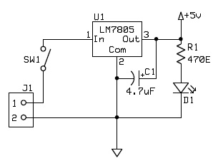
- Availability of 5V supply
LCD display required 5V supply for its operation. We designed a 5v power supply for this purpose.
Software Issues
- When interfacing Bluetooth bee with the SJ one board, the initially baud rate of the Bluetooth bee was set to 115200 rather than 9600. By connecting the output to voltage analyzer and calculating the frequency, we were able to calculate the baud rate in which the Bluetooth bee was operating.
Conclusion
This team project was a good learning experience for the team. We were able to learn how to communicate using GPIO, PWM, Bluetooth, NordicWoreless and UART interfaces. This project not only helped us to learn and improve our technical skills but also improved our team/work management skills.
Project Video
Project Source Code
References
Acknowledgement
We would like to thank Prof. Preetpal Kang for continued support during our project and helping us develop innovative concepts into applications. We appreciate his patience in making us understand the importance and wide applications possible through Real-Time Operating systems.
References Used
- Preetpal Kang, Professor, Computer Engineering, Charles W. Davidson College of Engineering, San Jose State University.
- Socialledge.com
- LPC1758 User Manual
- SJOne Board Schematics
- FreeRTOS Tutorial
- Git Tutorial
- C++ Tutorial
- Light Dependent Resistor Info
- Bluetooth Bee Info
- Bluetooth Module DataSheet
- Servomotor Info
- LS0003 Servo-motor DataSheet
- Nordic Wireless DataSheet
- Solidworks Cad Design Tool
- LM7805 DataSheet
- SparkFun Electronics
