S15: MP3 Player with Graphic Equalizer Display
Contents
Abstract
The SJ One Board, which contains an LPC1758 microcontroller, will play MP3 audio files from an SD card and display the audio frequencies on a graphic equalizer simulated by LED's, an MP3 audio decoder integrated circuit (VS1053), and equalizer analyzing IC (MSGQE7).
Introduction
An equalizer is a set of electronic filters that can adjust the frequency response of a sound system. A common type of equalizer is the graphic equalizer, which represents filter levels usually with light-emitting diodes (LED's). Depending on the integrated circuit used, a graphic equalizer shows the direct-current representation of a varying range of audio frequency bands. For instance, the MSGEQ7 CMOS IC splits audio in seven bands: 63Hz, 160Hz, 400Hz, 1kHz, 2.5kHz, 6.25kHz, and 16kHz. Commonly seen on audio devices and media software like Windows Media Player or VLC Media Player are simulated versions of audio spectra.
Objectives
Interface the MP3/Audio Decoder IC with Our Microcontroller
The first objective was to interface the MP3/Audio decoder IC (VS1053) with SJSU One board (LPC1758) using SPI bus with some additional pins for data transmit and reset purpose.
Design Software for the MP3 Player
The second objective was to design software for the MP3 player to read files from a SD card then transmit data to the MP3/Audio decoder IC to play and output sound.
Control the MP3 Player Using a remote control
The third objective was to read IR signal from a remote control using IR receiver on SJSU One board and make change on the MP3 player accordingly. Basic commands: play, pause, fastforward, rewind.
Construct Equalizer Analyzing Circuit
The fourth objective was to design the equalizer analyzing circuit using a MSGQE7 chip. The SJSU One board gives the RESET and STROBE signal to the MSGQE7. A 3.5mm audio jack was used to input the audio into the MSGQE7.
Team Members & Responsibilities
- Thinh Lu
- Writing VS1053 audio decoder driver
- Designing the MP3/Audio player
- Brian Nguyen
- Designing the equalizer analyzing circuit
- Andrew Pang
- Interfacing LED matrix with SJSU One board
- Editor-in-chief of project report
Schedule
This is our original plan and the status of each task.
| Week# | Ending date | Task | Actual |
|---|---|---|---|
| 1 | 4/18 | Order all hardware. | Completed. |
| 2 | 4/25 | Interface LED matrix with LPC1758.
Play a single MP3/Audio file. |
Completed. |
| 3 | 5/1 | Finish MP3 driver. | Completed. |
| 4 | 5/15 | Finish MP3 player.
Interface with a remote control. |
Both completed. |
| 5 | 5/22 | Interface LED's as graphic equalizer. Presenting on 5/25. | Completed. |
Parts List & Cost
Give a simple list of the cost of your project broken down by components. Do not write long stories here.
- (1) LED Matrix: $24.95
- (1) 12 V power supply: $11.59
- (1) 5/3.3 V power supply: $4.55
- (1) Mikro VS1053 breakout board: $21.90
- (20) jumper wires: $1.95
- (1) 4-pin Molex connector: $0.95
- (1) Electric tape roll: $0.95
- (2) Graphic equalizer display filter MSGEQ7: $4.95
- (1) Audio Jack 3.5mm: $0.95
- Breadboard, resistors, capacitors, all spare parts from previous CMPE courses
Total cost: $72.74
Design & Implementation
In this section, we will go over our hardware and software designs including sub-sections describing our design and implementation.
Hardware Design
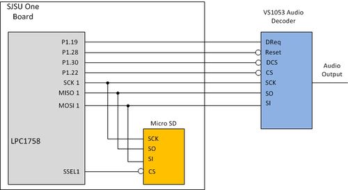
For the Mp3 Player, we use SPI interface to control and send/receive data from the decoder, VS1053.
As shown in Figure 1, this design uses four GPIO pins of the LPC1758 CPU including one for input and three for output. Pin 1.22 is used as output to control CS pin of the audio decoder. Pin 1.28 is used as output to control RESET pin of the audio decoder. Pin 1.19 is used as input to check the DREQ signal from the audio decoder. And pin 1.30 is used as output to control the DCS pin of the audio decoder. The audio decode shares SPI bus, SSP1, with the Micro SD.
Briefly, the pin functionality of the audio decoder can be described as follows:
- CS is chip select pin for SCI operation (to set up and control the audio decoder),
- DCS is a chip select for SDI operation (to play songs),
- RESET is to perform a hard reset on the audio decoder,
- and DREQ is used to notify when the decoder can receive more data (busy = 0, ready = 1).
The rest, SO, SI, and SCK, follow the SPI protocol, as explained in LPC 1758 and VS1053 datasheets.
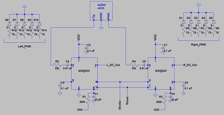
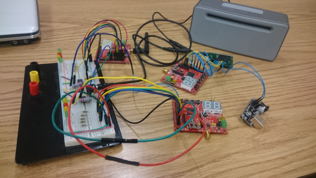
The two main components of the equalizer circuit were the audio jack and MSGEQ7 chip. The audio jack divides the audio into two audio channel, left and right. The left and right audio each go into the audio input of two seperate MSGEQ7. The MSGEQ7 is an audio spectrum analyzer chip with seven band-pass filters from 63 Hz to 16,000 Hz. Two MSGEQ7 chips were used to drive 2x5 LEDs. The MSGEQ7 is controlled with two digital signals, RESET and STROBE. A positive RESET signal is needed in order to start operation. The values of each of the bands can be read whenever seven negative pulses are inputted into STROBE. The values of the seven bands are analog values that are fed into an analog-to-digital converter (ADC) of two LPC1768. The ADC provides an us with a value between 0-4096 since the ADC resolution is 12-bit. The values from the ADC were divided by 40.96 in order to produce a value between 0 and 100. This new value is used in the pulse-width modulation in order to control the brightness of the 2x5 LEDs.
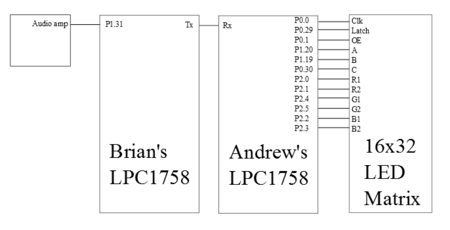
Initially, we planned on outputting the audio frequency spectrum on a 16-by-32 LED matrix, with connections shown in Figure 3 in which two LPC1758's would be connected by UART, then the LPC1758 interfaced with the matrix via GPIO connections. However, we could not implement this part and decided on an alternative design (see Problem #1 section below).
Hardware Interface
For the Mp3 player, we use SPI bus to communicate between the LPC1758, micro SD card, and VS1053. For the audio decoder, it has two operation modes, SCI and SDI. SCI is for control settings of the decoding process (volume, bass/treble value, clock speed, decoding/recording). And SDI is for receiving data; for example, when we want to play a song, we simply read the song from the SD card then send to the decoder, which is set up properly; the decoder will then just decode the data from the audio file and output sound to speaker/headphone. For driver, we break it down into small functions to set up the connection interface between the CPU and the audio decoder, to set up the audio decoder by sending the value to its control registers, to send a single byte as well as 32 bytes of data to the decoder to play songs.
Hardware Interface Driver
   LPC_GPIO1->FIODIR |= (1<<22);   //set pin P1.22 as output -- CS signal
   LPC_GPIO1->FIODIR |= (1<<28);   //set pin P1.28 as output -- RESET signal
   LPC_GPIO1->FIODIR |= (1<<30);   //set pin P1.30 as output -- DCS signal
LPC_GPIO1->FIODIR &= ~(1<<19); //set pin P1.19 as input -- DREQ signal
   LPC_GPIO1->FIOSET = (1<<28);    //set pin P1.28 high initially
   LPC_GPIO1->FIOSET = (1<<30);    //set pin P1.30 high initially
   LPC_GPIO1->FIOSET = (1<<22);    //set pin P1.22 high initially
ssp1_init(); //initialize ssp1
Software Design
LED Matrix
For interfacing the SJ One board with LED matrix, we intended to have the program activate a select number of LED's of a certain color, depending on audio frequencies read by the MSGEQ7 IC.
Pseudocode is as follows:
#define CLOCKPIN 0 // P0.0
#define LATCHPIN 29 // P0.29
#define OEPIN 1 // P0.1
#define APIN 20 // P1.20
#define BPIN 19 // P1.19
#define CPIN 30 // P0.30
#define R1PIN 0 // P2.0
#define R2PIN 1 // P2.1
#define B1PIN 2 // P2.2
#define B2PIN 3 // P2.3
#define G1PIN 4 // P2.4
#define G2PIN 5 // P2.5
while(1)
       /* Output to matrix display */
        GPIO0 FIOPIN: OEPIN bit = 1 // Disable output
       /* Select row */
         GPIO1 FIOPIN: APIN bit = 1
         GPIO1 FIOPIN: BPIN bit = 1
         GPIO0 FIOPIN: CPIN bit = 1
       /* Output color */
                 for(i = 0; i < 32; i++){
                   if row<8
                      GPIO2 FIOPIN: B1PIN bit = matrix[row][i]
                   else if(row>7)
                      GPIO2 FIOPIN: B2PIN bit = matrix[row][i]
                      GPIO0 FIOPIN: CLOCKPIN bit = 1
                      GPIO0 FIOPIN: CLOCKPIN bit = 1
         GPIO0 FIOPIN: CLOCKPIN bit = 1
         GPIO0 FIOPIN: LATCHPIN bit = 1
         GPIO0 FIOPIN: OEPIN bit = 1
Mp3 Player
Our focus in this project was on the whole system, an MP3 player with LED equalizer display. The system runs on FreeRTOS, reads a song list from a text file, and adds song names into a vector. Afterwards, the system reads the files in order, then sends to the audio decoder to decode and output sound to a speaker and the equalizer analyzing circuit. This accommodates further development; for example, we originally planned to establish communication between the player and a remote control but were precluded by time constraints. With FreeRTOS, we can schedule and synchronize tasks to do different jobs on realtime. So having other tasks to communicate with a remote control and control the player accordingly is a possible improvement.
Pseudo code for Mp3_Player task:
    open(songlist.txt) //read the songlist
    gets(line) //read line
    songnameVector.push_back(line) //push song names into vector
    while(open(songnameVector.front().c_str()) //open file from the SD card
    sendtoDecoder(buffer) //send data to the decoder
    songnameVector.rotateRight() //rotate the vector to get the next songname
Equalizer Circuit
The following code was used to start the equalizer and to collect 7 spectrum values. Reset is set high for one microsecond and strobe is set low. While the strobe is low, the value of the bands are read and saved into an array named spectrum. After saving the value in an array, the strobe is set high again and the process repeats.
    while(1)
   {
       reset.setHigh();
       delay_us(1);
       reset.setLow();
       delay_us(75);
       for(int i=0;i<7;i++)
       {
           strobe.setLow();
           delay_us(40);
           spectrum[i] = adc0_get_reading(3)/40.96; // Read the value of ADC-3
           strobe.setHigh();
           delay_us(40);
       }
    }
Implementation
Audio Decoder Driver
To set up the audio decoder, VS1053, these are the basic steps:
   Do a hardware reset
   Set up the Mode Register //for normal operation use 0x0800
   Set up BASS/TREBLE Register //set to the value desired
   Set up the Clock Register //0x2000 for default clock 12 288 000 Hz
   Set up the AudioData Register //0xAC45 for sample rate of 44100 Hz
   Set up the Volume Register
To send a song to the audio decoder, VS1053, these are the basic steps:
   Check DREQ signal //wait if it is 0 -- busy
   Send 32 bytes of data //as recommended by the manufacturer
   Read the AdditionalParameters Register //to see if any actions needed
Equalizer Driver
The following are the steps to display the equalizer output on the LEDs:
   Send a high signal for 1us to Reset
   Send a low signal to Strobe
   Read value of band into array
   Divide spectrum value by 40.96 to obtain value for PWM
   Send a high signal to Strobe
   Set PWM value to light LED
Testing & Technical Challenges
One of the advice after going through all the issues during our testing process is that always understand the basic knowledge of the hardware design. Always try to fully understand how each device behave and do the task we assign to it. With all that, the testing and troubleshooting process shouldn't be too complicated.
Following are the testing results of our design, as well as encountered issue.
Audio Decoder Driver and MP3 Player Testing
For the driver for SPI communication between the CPU and VS1053 IC, after troubleshooting the issue with one of the GPIO pin, the testing process is straight forward and showing that all the features work with no issues. For example, we can set up the IC correctly and read values from its control registers.
Our MP3 Player is able to read a file containing a songs list then pushes the songs names into a vector; after that, it just keeps playing the song one after another unless it receives a signal from switch 1, meaning that it skip to the next song. The testing process for the MP3 Player is pretty straight forward.
PWM Value Testing
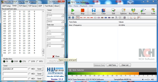
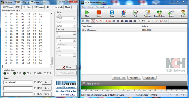
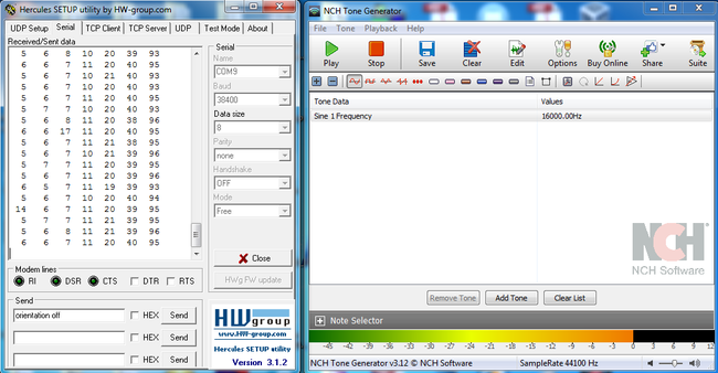
In order to verify that our values from the ADC are accurate, we used a tone generator. A tone generator produces a specific frequency at one of the bands which we can use observe on Hercules. In Hercules the first column of numbers is the values gathered from 63Hz. The second through seventh columns are 160Hz, 400Hz, 1000Hz, 2500Hz, 6250Hz, and 16000Hz respectively. If for example we used a 63 Hz sine wave in the tone generator we can expect the first column in Hercules to produce a higher number compared to the other six columns.
Issue #1: Programming LED matrix
Our original plan was to output graphic equalizer via a 16-by-32 LED matrix. However, with the method we used to connect the matrix to the SJ Board GPIO pins, we could not light up the matrix interfaced with the board. In the end, we decided to output the graphic equalizer via five LED's on a breadboard, instead. We advise future aspiring engineers to research about available libraries or ask an expert before attempting to interface hardware with a microcontroller.
Issue #2: Additional PWM signal
Our design needed seven PWM signals in order to properly display each of the seven bands. The SJ-One board provides six PWM pins for use. We tried to configure a another pin, P0.20, as a PWM pin but were unsuccessful. We had a choice of using six or five PWM signals to display the equalizer. In the end, we decided to use five PWM signals for symmetry. For the LED display, The 160 Hz and 6250 Hz bands were not used.
Issue #3: GPIO pin is defective
Our hardware design for the connection between the board and the VS1053 IC originally used pin 0.29 as the control signal for CS of the audio decoder. However, the original design didn't work. The issue was the GPIO pin 0.29 of the SJSU One board; it might be defective or require a pull up resistor. Everything worked just fine with pin 1.22 as the new CS pin. This issue took us some time to figure out since we were into Serial Clock Speed issue assumption. So for future reference, if you encounter this problem, when you cannot control CS signal the audio decoder at all, try to check the output level of all the GPIO pin first. It might save you some time.
Conclusion
An MP3 player is an embedded system because within a greater electrical system, the player has the express purpose of opening MP3 audio files and outputting the audio frequency via LED's, through a graphic equalizer circuit. The LPC1758 microcontroller uses SPI bus to communicate with the MicroSD card to read the audio file and VS1053 audio decoder, which then outputs to a seven-band graphic equalizer MSGEQ7 that splits the audio into several bands of varying frequencies, as well as to a speaker system. Rows of LED's display the filter levels of each band. Programming the audio decoder involves resetting the hardware, then setting proper registers (mode, bass/treble, clock, etc.) for sound levels and data. Sending a song to the decoder sends the title and other relevant metadata to a vector.
With this project, we developed skills in communication, division of labor, and time management. We have gained experience in using FreeRTOS as a platform for our further development in realtime system. Especially with this project, we learned more about using SPI bus to communicate between devices.
Future students who wish to pursue this type of project should learn the basics first; we must always try to learn and build things from scratch, not depend on existing libraries. This is because when an issue emerges, we will always be able to trace back to the root of the problem and troubleshoot it, from original work. Controlling an LED matrix will take some effort to learn how to control each and every row, column, and the colors of it. Using FreeRTOS to implement the MP3 player is a highly efficient method; further implementation of this project could be creating tasks that will perform different jobs like reading a file, sending data to the audio decoder, or reading data from the equalizer circuit.
Project Video
Upload a video of your project and post the link here.
Project Source Code
References
Acknowledgement
Acknowledgements to Sparkfun for providing components used, as well as lab instructor Preet Kang for his guidance in this project and throughout the semester. Special thanks to this group for a very detailed guidance to complete the mp3 player. They actually built a very convenient library used for simplifying the cstring operation. And we used it as is in our project for reading/storing file names.
References
- A. Dumbre, C. Vaidya, and K. Beadle. (2014). S14: Spectrum Analyzer for Audio Frequency Signals [Online].
- R. Huisinga. (1996). Equalizer [Online]. Available: http://web.archive.org/web/20100112045434/http://www.soundinstitute.com/article_detail.cfm/ID/110
- Mixed Signal Integration. (2004). Seven Band Graphic Equalizer Data Sheet [Online]. Available: http://www.keil.com/dd/docs/datashts/philips/lpc17xx_um.pdf
- NXP. (2010). UM10360 LPC17xx User Manual [Online]. Available: https://www.sparkfun.com/datasheets/Components/General/MSGEQ7.pdf
- T. Pantels. (2012). S12: Remote Controlled MP3 Player [Online].
- VLSI Solution. (2014). VS1053b Datasheet [Online]. Available: http://www.vlsi.fi/fileadmin/datasheets/vs1053.pdf
