S12: VAndroid
Contents
- 1 Project Title
- 2 Abstract
- 3 Objectives & Introduction
- 4 Parts List & Cost
- 5 Design & Implementation
- 6 System Hardware Interface
- 7 System Software Design
- 8 Testing & Technical Challenges
- 9 Conclusion
- 10 References
Project Title
VAndroid: The Vehicle Controlled By Android.
Abstract
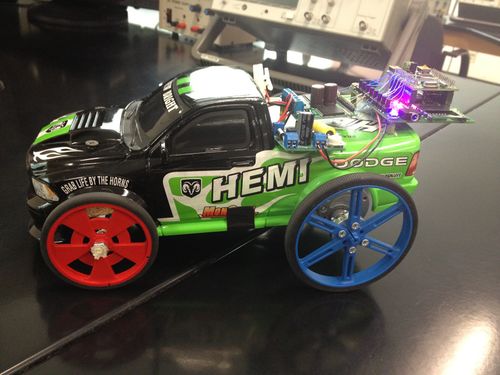
This CMPE 146 Embedded System Final Project consisted of constructing an Android controlled vehicle. The purpose of this project was to incorporate the the major components that will be used to complete the Senior Project: "Seglite: Self-Balancing Robot controlled by Android". This was accomplished by building a car from scratch to incorporate usage of the motors, motor controller, bluetooth module, and LPC2148 microcontroller. Ultimately the goal of this project is to create an android application to communicate via the bluetooth module with the LPC2148 CPU to control the vehicle's direction and speed.
Objectives & Introduction
The objective is to create VAndroid, the vehicle controlled by Android!
Team Members
- Josh Peters
- Everardo Ochoa
- Shadi Massad
Roles & Responsibilities
| Name | Alias | Role | Responsibilities |
|---|---|---|---|
| Josh Peters | "The Hammer" | Leader | Bluetooth Communication/Android/Testing |
| Everardo Ochoa | "The Mechanic" | Mechanic | Motor Control/PWM Drivers/Built Car |
| Shadi Massad | "The Tank" | Assistant Mechanic | Motor Control/PWM Drivers/Testing |
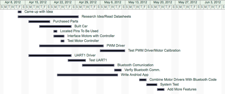
Schedule
Parts List & Cost
| Hardware Requirement | Specification | Purchased From | Price |
|---|---|---|---|
| Microcontroller | ARM7- NXP LPC2148 | sjvalley.com | $59.99 |
| (2) Motors | 29:1 Metal Gearmotor 37Dx52L mm with 64 CPR Encoder | pololu.com | $39.95 ea |
| Motor controller | Dual VNH2SP30 Motor Driver Carrier MD03A | pololu.com | $59.95 |
| Bluetooth module | Bluetooth TTL transceiver module | eBay | $14.99 |
| Android phone | Android OS | N/A | Free |
| Voltage regulator | Voltage regulator 7805 | RadioShack | $1.99 |
| Battery Pack and Charger | Tenergy 9.6V 2000mAh NiMH Battery Pack | Fry's Electronics | $22.99 |
Design & Implementation
This project was completed in a number of steps.
1)Motor control with the LPC2148
2)Bluetooth communication with the LPC2148
3)Android Application
1. Motor control with the LPC2148
Motor Hardware implementation:
This project used brushed DC motors with a 29:1 metal gearbox ratio. At low speeds, DC motors provide little torque and minimal position control, making them useless for position control applications. These motors were designed to be used at 12 V, but can function with much lesser input voltages. It is a very powerful and heavy motor operating at 9.6V because of the limitations of our battery pack.
A freely running motor (no load) will draw little current. Stall current rating specifies the amount of current is drawn at the moment the motor stalls. The torque rating is the amount of force the motor can exert on load. A motor with a high torque rating will put forth a larger force on a load placed at a tangent to its rotational arm than a motor with a lower torque rating.
Applying a high (+12 V) signal to the forward input makes the motor rotate in the forward direction. Conversely, applying a high signal to the reverse input makes the motor rotate in the reverse direction. Applying a voltage at both inputs is not permissible for a single motor. The higher the input voltage, the more torque is generated the motor.
For testing purposes, this is easily seen when switching the black and red wires of the motor between power and ground. However, this is not practical when the motors are mounted in a robot. A device that switches the motor direction automatically is needed.
Motor Controller Hardware Implementation
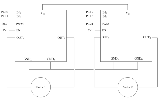
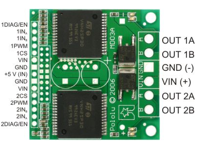
The motor controller we will be using is the Dual VNH2SP30 Motor Driver Carrier MD03A. This component is a full bridge motor driver that helps us manipulate the direction of each motor. A microprocessor is used to turn the H-Bridges on and off. This component can handle a pulse width modulation (PWM) of up to 20 kHZ, which is generated by the microprocessor. This is most efficient way of controlling the speed of a motor. To be more specific, the width of the applied pulse, as well as the period between pulses, controls the speed of the motor.
The DIAG/EN pins, when connected to an external pull-up resistor, can enable one leg of the H-Bridge. These pins also provide the system with a diagnostic feedback signal. These pins are not required, and can be left unconnected if you do not want to monitor fault conditions of the motor driver. The input pins control the direction of each motor, while PWM dictates the speed of each motor.
The two VIN pins on the left hand side of the board power up the two ICs. The VIN pin on the right hand side of the board powers the motors. The CS (current sense) pin lets the system monitor the amount of current in each motor.
Operating condition of motor controller
| INa | INb | ENa | Enb | OUTa | OUTb | Operating Mode |
|---|---|---|---|---|---|---|
| 1 | 1 | 1 | 1 | H | H | Brake to Vcc |
| 1 | 0 | 1 | 1 | H | L | Clockwise |
| 0 | 1 | 1 | 1 | L | H | Counterclockwise |
| 0 | 0 | 1 | 1 | L | L | Brake to GND |
Motor Software implementation:
Intialize PWM:
PWM Pin Selection:
There are a total of 6 PWMs available on the LPC2148; however, most of them are in use by UART0 and UART1. That leaves two PWMs for use, PWM 2 and 5.
- Select p0.7 for PWM 2
- Select p0.21 for PWM 5 Note: p0.21 is used in previous labs that use the SD Card, and existing SD Card code must be removed.
- Set the two PWM pins as outputs (IODIR0)
Set PWM control using Chapter 16 from the LPC2148 Datasheet:
- First set the PWM Precale Register (PWMPR) to 0, which specifies the maximum value of the PWM prescale counter
- Next, set the PWM Control Register (PWMPCR) to 0, which disables and deselects all bit channels to generate a single edge controlled PWM. Then use this register to enable the outputs of both PWMs.
- The max value of the pulse width is generated by setting the Match Register (PWMR0). 19kHz was calculated and used.
- Reset PWMMRC when matched with PWMMR0
- Latch in all PWMMR's by setting the PWM Latch Register (PWMLER) to 0x7F. This number is obtained by setting all 7 bits of the register to 1.
- Reset the counter using the PWM Timer Control Register (PWMTCR). This is done so that the PWM Timer Counter and the PWM Prescale Counter are synchronously reset on the next rising edge of PCLK.
Configure Motor Pins:
One must clear bits of a pin, before setting its direction (either input or output).
Motor controller pins for PWM 2:
- Pins p0.10 and p0.11 initialized as outputs on the LPC2148 that input to the first H-bridge on the Motor Controller module.
Motor controller pins for PWM 5:
- Pins p0.12 and p0.13 initialized as outputs on the LPC2148 that input to the second H-bridge on the Motor Controller module.
Motor Direction:
To move the motors forward, the two input pins on the H-bridge must be the inverse of each other.
IOSET0 = (1 << 10); //PWM2
IOCLR0 = (1 << 11); //PWM2
IOCLR0 = (1 << 12); //PWM5
IOSET0 = (1 << 13); //PWM5
To move the motors backwards, the input pins for the H-bridge must also be the inverse of each other. However, the pins that are cleared in the forward case are now set, and vice versa.
IOCLR0 = (1 << 10); //PWM2
IOSET0 = (1 << 11); //PWM2
IOSET0 = (1 << 12); //PWM5
IOCLR0 = (1 << 13); //PWM5
To stop the motors, all four pins are cleared.
IOCLR0 = (1 << 10); //PWM2
IOCLR0 = (1 << 11); //PWM2
IOCLR0 = (1 << 12); //PWM5
IOCLR0 = (1 << 13); //PWM5
Now that the motors have been configured, its time to make them rotate. Adjusting PWMs was used to make the VAndriod move. Not only is the device capable of turning right and left, it can also reverse in both directions as well.
To turn left, the motor on the left (controlled by PWM5) must move at a slower speed than the motor on the right (PWM2). How sharp of a turn depends on how fast the motor on the right is moving compared to the slower one on the left. For instance, if the left motor was completely turned of, while the right was rotating quickly, the VAndriod will move a circle around the left wheel. The same process is done when the VAndriod tuns right. Its just that the right motor has to move slower than the left.
The VAndriod is programed to operate at high speeds and low speeds, so the motors were calibrated and the proper PWM values were noted for each case.
Motor Task Pseudocode:
This was implemented for every driving mode that was created for this experiment. The only things that changed throughout every case was the function that sets the direction the motors will spin. In addition, the PWM values that are used to execute the direction to drive in. For example, to turn left when driving foward the PWM value for the right motor must be higher than the PWM value for the left motor.
for(;;)
{
  if(character received by queue)
  {
    SwitchCases(character received by queue)
    {
      case forward:
        if(speed_set_fast)
        {
           setFast_Pwm2;//this value is different for each case
           setFast_Pwm5;//this value is different for each case
        }

        else
        {
           setSlow_Pwm2;  //this value is different for each case
           setSlow_Pwm5;  //this value is different for each case
        }

        setPWM();       //initializes Pwm

        Forward();      //sets motor pins to drive forward

        while(timer < 500)
        {
           vTaskdelay(1);
           timer++;
        }

      timer=0;

      stop();         //stop the motors

      break;

     }
   }
 }
2. Bluetooth Module
BLUETOOTH Hardware implementation:
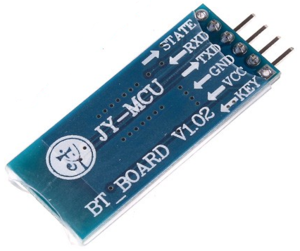
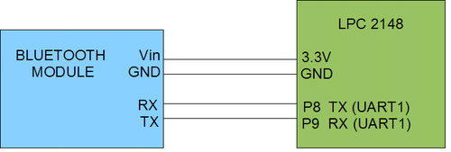
A cheap Serial Bluetooth module from eBay was purchased for $15 including shipping. The module has 4 pins: RX, TX, Power and Ground. Although the module is labeled 5V, connecting it directly to the LPC2148 3.3V output seems to work fine. Also make sure to connect it to the LPC2148 ground or share a common reference ground.
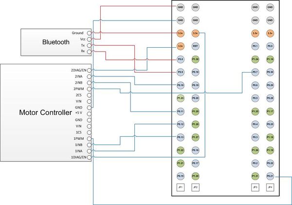
Connections must be made as shown below.
BLUETOOTH Software implementation:
The Bluetooth module uses UART1 on the LPC2148. In order to communicate, a driver must be written for UART1. The driver we implemented was based of the provided UART0 driver. This is converted for UART1 by changing all appropriate register names from UART0 to UART1. NOTE: it make take several pass through of the driver line by line before this is done correctly. Refer to the datasheet often. ALSO REMEMBER TO CHANGE THE INTERRUPT VECTORS in function uart1Init as shown below. (vector 6 does not have to be used, but it should be an even number that is not already being used.)
After UART1 is written, a Bluetooth task is also needed. The bluetooth task works as follows:
- initialize UART1 (note: baud rate is 9600 fot he bluetooth module)
- use function uart1GetChar to take in a character sent over BLUETOOTH and store in a byts called data
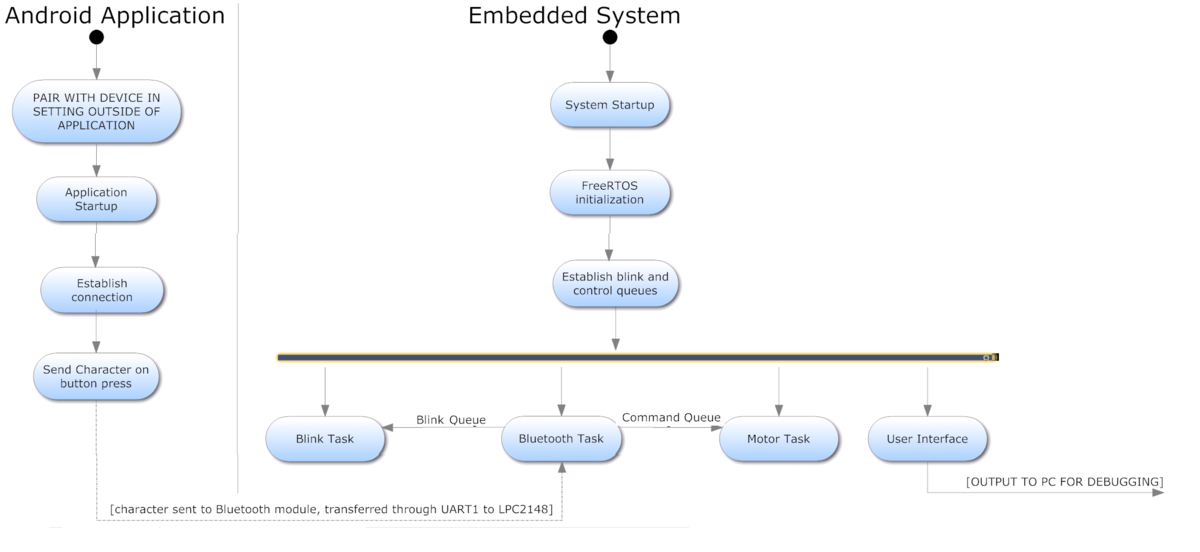
- if data matches a functional character, send the data through the command queue and blink queue which connect to the motor task and blink task respectively. (queue's shown in the System Software Design below)
Software and hardware verification:
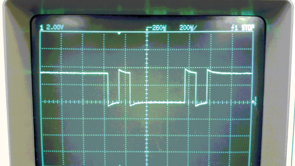
To verify UART1 is working properly, create a task that outputs a character with a small delay. Then use an oscilloscope to verify the character is being sent. The image below is of the character ‘A’ being sent on UART. Note: it appears UART sends the character backwards based on the waveform. This doesn’t affect the communication, just a surprising factoid.
To verify the Bluetooth module works properly it necessary to pair the devices. First, power on the LPC2148 (which powers on the Bluetooth module) and turn on an Android device. On an android device, open SETTINGS -> WIRELESS AND NETWORKS -> and make sure the Bluetooth box is checked. Then select BLUETOOTH SETTINGS -> SCAN FOR DEVICES and select “linvor”. Enter the passcode of “1234”.
Now that the Bluetooth module and the android device are paired, download the app for android: SENA BTerm Bluetooth Terminal This terminal application establishes a connection between linvor and android device. Since the LPC2148 is already programmed to output character ‘A’ on UART1 which is connected to the Bluetooth module, you should now see it appear on the terminal on the phone.
At this point communication between the LPC2148 and the android device is verified.
3. Android Application
Before even thinking about an application, all the tools need to be installed. For this project, we followed this tutorial for tool setup and this tutorial for making a first application and getting familiar with the android environment.
Writing an application from scratch takes forever and without knowledge of Java and Xml given the time constraints, many errors can result. Therefore, this project used the provided Bluetooth Chat sample code from the Android SDK and was modified to fit the goals of this project.
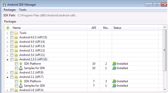
To download the sample code: Go to the navigation menu click Window->Android SDK Manager and make sure the sample code has been downloaded and the SDK platform for the specific version of device used. Since the phone used Ran Android 2.3.4, this project used the Android 2.3.3. Once completed the files will be located in the SDK folder on the machine used. Copy and paste them all into the relevant new project folder created.
The next goal was to establish communication with our Bluetooth module on the LPC2148. The BluetoothChat sample project does not include this functionality!!!! After extensive google searching, this blog was found which said to change the following line of code within the file BluetoothChatService.java. Below shows the original line of code which was commented out and below is the new one that replaced it.
Once that is done, the BluetoothChat application can now communicate with a terminal on a PC. To test it use a PC or an application on another phone called Sena BTerm and verify two-way communication.
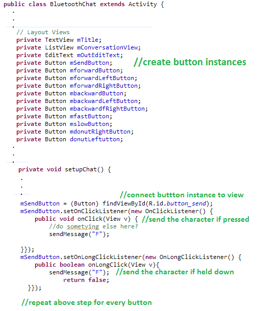
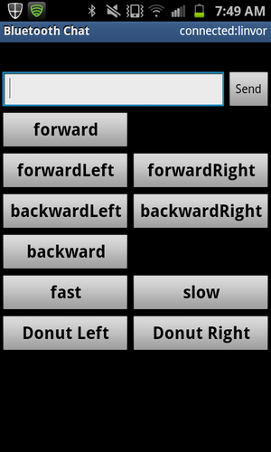
The app should connect and you should be able to send a character to the LPC2148 by typing it in and hit send. However the next step is to add buttons that send a dedicated character to the LPC2148. Under main.xml insert a table from the layouts and click and drop buttons in place. In strings.xml add the appropriate strings for the button names. Now change the BluetoothChat.Java file as shown below.
Make a button for every function. The function name and character sent are shown in the table below.
| Character | Function |
|---|---|
| F | Forward |
| R | Forward Right |
| L | Forward Left |
| B | Backward |
| S | Backward Left |
| T | Backward Right |
| X | Fast |
| W | Slow |
| D | Donut Right |
| C | Donut Left |
As a side note, it was difficult to figure out how to change the layout of the appliocation. If I tried to remove a field from the app layout screen the application would crash, even if I removed all the underlining code that relied on that field (maybe I missed one somewhere but it was difficult to debug in a short time). Therefore I just made what fields I could smaller and changed the function of the send button to just tell the car to drive forward).
System Hardware Interface
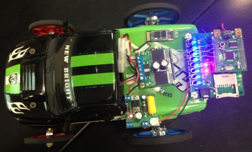
VAndroid was implemented using UART Serial Communication for means of communication between the bluetooth module and the LPC2148 microcontroller. The system was implemented using two UART drivers: UART0 and UART1. The UART0 driver was used for debugging purposes and to program the microcontroller board. The UART1 driver was used to establish communication between the bluetooth module and the microcontroller. The bluetooth module uses two pins: Rx and Tx, to transmit and receive data. In addition, GPIO (General Purpose Input/Output) pins on the LPC2148 microcontroller were used to control the direction of the motors. The interfacing of the LPC2148 board, motor controller and bluetooth module can be seen below.
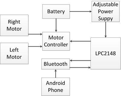
The system block diagram below shows the overall flow of VAndroid's system. Firstly, the 9.6V battery is used to power up the the motors via the motor controllers. The battery power is also regulated via an adjustable power supply that regulated the 9.6V to 5V. The regulated 5V power is used to power up the microcontroller. The android application that was created sends a character to the microcontroller via the bluetooth module. The microcontroller analyzes the data and performs the action based on the input, which will generate the control signals for the motors to move. Separate tasks were used to handle the bluetooth data, motor actions, and the LED blinking. The system was designed using to a counter that will execute the task for 500 milliseconds based on the button pressed on the application.
System Software Design
| Task | Description | Outline |
|---|---|---|
| Bluetooth Task | Receives a character from the Bluetooth module using UART1 and sends it to the command queue and blintask queue |
|
| Motor Task | Receives a character from the command queue and operates the motors accordingly. |
|
| Blink Task | Blink the lights on the board when a command is sent in the blink queue |
|
| User Interface Task | Debugging Task - used to monitor other tasks CPU usage | provided |
Testing & Technical Challenges
Technical Challenges:
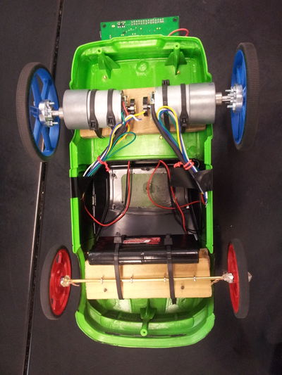
The challenges encountered throughout this project began at an early stage. The parts that were purchased for this project were ordered before the final project was assigned. The motors were ordered based on research obtained from our senior project experiment. The motor controller was ordered from the same website that the motors were ordered from, under the impression that they would be easy to interface. However, the motor controller datasheet was confusing and unclear. It took longer than expected to read the datasheet and comprehend the layout of the motor controller board. In addition, during the implementation of the PWM driver we had included a clock divisor to set up the PMW clock, PCLK, which is used for peripheral devices. This line of code prevented the motor task from working simultaneously with the bluetooth task. When the Android application sent a command the motor task, the motors would not work. The entire code was debugged, and the error was narrowed down to this line of code. It was simply removed because it had be initialized in another task, and was causing conflict. Once the change was made, both tasks began executing commands correctly. Another issue that was encountered once the vehicle was established was that one motor was faster than the other right out of the box. In addition, since only two motors were being used to handle forward, backwards, and turning. The group encountered a challenge of mounting two free-wheels that simply were there to support the vehicle. Since we were creating our own car this posed as a challenge because it was unclear on how it could be accomplished. There were parts that could be ordered online, but due to time constraints it was not plausible. Using engineering thinking methods we simply took a trip to a hardware store and bought a brass rod, small hooks, and steel nuts. The idea was to solder the two nuts, one on each side of the wheel to maintain it at a fixed position and to allow it to spin. However, when trying to do this the entire rod would heat up and melt the solder away. Desperate for a quick fix, a hot glue gun was used to secure the nuts onto the rod. The challenge with building the car was that nobody in our group had the power tools available on campus needed to fix the issues we came across.
Testing:
There was a lot of testing done with the PWM values to achieve the performance wanted since one motor was faster than the other. The only way to solve this issue was with software. However, for example in the forward case for slow speed the PMW2 value was 0x00000080 and PWM5 was 0x00000095. PWM2 controls the faster motor and PWM5 is for the slower motor. Ideally the motors should have of functioned under the same PWM value to move the vehicle straight forward. This issue caused us to perform trial-and-error testing to get the car to move in the direction desired. The PWM values varied a lot between each direction.
Conclusion
In conclusion, the objective of this final project was to make a wireless android controlled vehicle. This goal was accomplished using more than half of the parts that will be used during our senior project. All the objectives for this project were met and the final product worked smoothly. Many challenges were overcome during this project and a lot of knowledge and experience was gained. Our group worked well together, great communication and relationship was built. It is crucial to establish a good working atmosphere amongst the group. Overall, we were satisfied with the goals that were set and met for this class. Our group had a blast working on this project. Our group would like to suggest future groups to get a project plan established early, stick to the schedule, order parts early, and divide the workload as evenly as possible amongst the group members.
References
Acknowledgement
- Dr. Ozemek
- Preet Kang
- Bryan
References Used
- LPC2148 DataSheet
- PCA9535 Port Expander Datasheet
- http://android-meda.blogspot.com/2012/01/installing-android-development-tools-in_21.html
- http://android-meda.blogspot.com/2012/01/writing-your-first-android-app-body.html
- http://www.anysparechange.co.uk/blog/?p=33
