S12: Traffic Light Sensing Vehicle
Contents
Light Color Sensing Vehicle
Abstract
The report is constructed for the final project of the undergraduate Embedded System Course at San Jose State University. The main objective is to build a miniature vehicle that can distinguish color emitting from multiple LED light sources. The vehicle will stop, forward/reverse depending on the color of light present. This project uses knowledge from previous laboratory experiments on FreeRTOS operating system, building SPI and I2C drivers, configuring ports, etc. to accomplish the main goal.
Objectives & Introduction
This main objective of this project is to build a miniature vehicle that can stop, move forward/reverse according to different color light sources. The main components used in this project are an ARM7 LPC2148 Development Board, ShiftBrite LED modules, and light color sensor ADJD-S311-CR999.
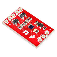
The ARM7 LPC2148 Development Board is a microcontroller with an ARM7 processor. The package consists of USB connectors, reset button, etc. This microcontroller is programmed in C language with FreeRTOS as its operating system. ShiftBrites are LED modules manufactured by macetech that integrate Allegro A6281 3-channel constant current LED driver with a large, high-brightness RGB LED. This LED module can produce up to 1,073,741,824 possible color combinations. The ADJD-S311-CR999 light color sensor is the main component for this project. It is a 4 channel digital sensor with mere size of 2.2x2.2x0.76mm. With 10-bit per channel resolution, ADJD can discern the smallest differences between visible colors. The sensor is packaged as an evaluation board by Sparkfun Electronics.
In order to accomplish the main goal, the following objectives are needed:
- Design and interface LED modules, light color sensor
- Construct PWM driver for motor controller
Team Members
- Warren Ou
- Thinh Duong
Roles & Responsibilities
| Member | Roles & Responsibilities |
|---|---|
| Thinh Duong | RGB LED driver |
| Warren Ou | PWM driver and Light Sensor Tasks |
Parts List & Cost
| Part Name | Price | Link |
|---|---|---|
| ARM7 - NXP LPC2148(1) | $59.99 | [1] |
| ShiftBrite LED modules (3) | $4.99 | [2] |
| Light Color Sensor (1) | $14.95 | [3] |
| RC Toy Car (1) | $14.99 | [4] |
| Motor Controller (1) | Unknown | None |
Design & Implementation
The section covers the hardware and software designs.
Hardware Design
This project requires the hardware implementation of:
- ShiftBrite LED modules
- Color Sensor
- Motor Controller
SHIFTBRITE MODULES
ShiftBrite LED modules require at least 5.5V for minimum operating mode. However, the best result is obtained using a voltage between 6.5V and 9V. One ShiftBrite module has one RGB LED and an Allegro A6291, a small controller chip. The A6281 provides 10-bit PWM and 70bit current control signal for each of the red, green and blue LEDs. It uses a simple clocked serial interface to receive a 10-bit brightness value for each color, resulting in over a billion possible colors. Each input is buffered and output to the other side of the module. This allows each ShiftBrite to repeat the signal to the next, allowing cascaded LED modules without using an excessive number of I/O pins. [5]
| Specification | |
|---|---|
| Controller: | Allegro A6281 |
| LED Brightness: | 8000 mcd per color |
| LED Viewing Angle: | 140 degrees |
| Current: | 60mA maximum (all channels on) |
| Power supply: | 5.5V to 9V |
| PCB Size: | 0.8 x 0.8 inches |
| Pin Spacing: | 0.1 inches |
| Pin Pitch | 0.6 inches( wide DIP) |
COLOR SENSOR
The ADJD-S311-CR999 is a cost effective, 4 channels (RGB + CLEAR) digital output sensor in miniature surface mount package. It is a CMOS IC with integrated RGB filters and analog-to-digital converter front end. This devide is designed to cater for wide dynamic range of illumination level and is ideal for applications like portable or mobile devices, which demand higher integration, smaller size and low power consumption. Sensitivity control is performed by the serial interface and can be optimized invididually for the different color channel. The sensor can also be used in conjuntion with the on board white LED for reflective color management. [6]
MOTOR CONTROLLER
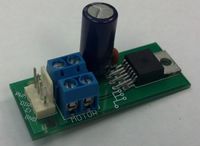
This motor controller has 4 ports (PWM, direction, EF, GND). This motor has a voltage converter 5V integrated on board. The PWM and DIR pins are used in this project to control the back motor of the vehicle. Error Flag (EF) was not used.
Hardware Interface
ShiftBrite Driver
Each ShiftBrite module requires 6 necessary connections including: power, ground, data, clock, latch, and enable. The following table shows the pin connection bettween one ShiftBrite module and LPC microcontroller
| LPC2148 Pin | ShiftBrite Pin | Description |
|---|---|---|
| P0.4 | Data In | Data Pin |
| P0.5 | Latch In | Latch Pin |
| P0.6 | Enable In | Enabling the module |
| P0.7 | Clock In | Clock |
| GND | GND | Common Ground |
The communication between ShiftBrite and microcontroller can be established using SPI interface. However, for simplicity purpose, in this project the communication was done using "bit-banging" method. That is, all the necessary pins for the communication are set to General Purpose In and Out Mode, and to "output" on LPC 2148. To set port P0.4 to P0.7 to GPIO, it only takes one line of code
PINSEL0 &= ~(0xFF<<8); //setting port P0.4 to P0.7 to GPIO
This line of code sets P0.4 to P0.7 to GPIO according to the datasheet for LPC2148
Next is to set all those ports to be output. This is done using IODIR, GPIO Port Direction control register in LPC2148. Port n is set to output if bit n of the IODIR register is set to 1
IODIR0 |= (1<<4); // setting port P0.4 to output
PWM
Steps to Initialize PWM
- select a pin and assign it to PWM using PINSEL
- select the direction of the pin as output(1) using IODIR
- disable counter register PWMPCR
- enable desired PWM pin in counter register PWMPCR
- select frequency of PWM by writing to register PWMMR0
- enable desired PWM latch in register PWMLER
- reset counter register PWMTCR
- enable counter register and enable desired PWM in register PWMTCR
| LPC2148 Pin | PWM Pin | Description |
|---|---|---|
| P0.8 | PWM | Pulse Width Modulation |
| P0.9 | DIR | Direction |
| GND | GND | Common Ground |
Color Sensor
Steps to Initialize Color Sensor
- write value [0-15] for each color capacitor register
- higher values yield smaller digital outputs
- write value [0-4095] for each color integration register
- higher values yield larger digital outputs
| LPC2148 Pin | Sensor Pin | Description |
|---|---|---|
| P0.2 | SCL | Serial Clock |
| P0.3 | SDA | Serial Data |
| GND | GND | Common Ground |
| 3.3V | 3.3V | Power |
Software Design
Show your software design. For example, if you are designing an MP3 Player, show the tasks that you are using, and what they are doing at a high level. Do not show the details of the code. For example, do not show exact code, but you may show psuedocode and fragments of code. Keep in mind that you are showing DESIGN of your software, not the inner workings of it.
- RGB LED
This project required three ShiftBrite LED modules which will be set to Red, Green, Blue. To accomplish this, understanding how to use and control a chain of ShiftBrite is crucial.
- Power Connection : The V+ and GND pins power both LED and the control chip. ShiftBrites require up to 60mA per module when all LEDs are active. The supply voltage should be kept between 5.5V and 9V.
- Data In/ Data Out: DI (Data In) pin carries the actual control information into the ShiftBrite. It is the input to an internal 32-bit shift register. Every time data is shifted into the controller, the binary value on the DI pin is places in Bit 0 of the shift register, and the next value in Bit 31 overflows out the DO (Data Out) pin to the next ShiftBrite in the chain. Data is shifted in using MSB.
- Clock In / Clock Out: CI (Clock In) pin controls teh shifting process. Each time the CI pin is sent a logic high and low, data is shifted into the DI pin and out of the DO pin. The CI signal is passed through the ShiftBrite to the CO pin.
- Latch In / Latch Out: The LI (Latch Input) in causes the ShiftBrite to accept whatever is in its shift register as a new command.
- Enable In / Enable out: EI (Enable Input) turns teh entire chain on and off. If it is sent to logic high, then it will black all ShiftBrites. When EI is low, all ShiftBrites will display the colors specified previously
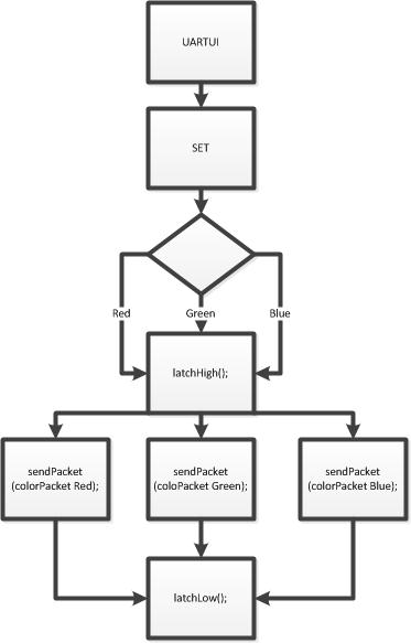
The following diagram illustrates how to set one ShiftBrite module to a certain color desires
All ShiftBrite control functions are put in UartUi Task. For example, if one needs to set the first module in the chain, simply type "set red" in Hercules.
- LatchHigh() / LatchLow() : These two function setting the latch bit on ShiftBrite chain to logic high and low by either set the port in LPC2148 to "output high" or "output low"
IOSET0 = (1<<5); //set latch pin (P0.5) to logic high
IOCLR0 = (1<<5); //set latch pin (P0.5) to logic low
- ColorPacket() contains packet (32-bit data) which is the information (integers) to set the LED to certain color. It ranges from 0 to 1024 (0 is the "light off" and 1024 as the brightest)
typedef union ShiftBritePacket
{
   unsigned long value;
   struct
   {
       unsigned greenDotCorrect:7;
       unsigned clockMode:2;
       unsigned :1;
       unsigned redDotCorrect:7;
       unsigned :3;
       unsigned blueDotCorrect:7;
   };
   struct
   {
       unsigned green:10;
       unsigned red:10;
       unsigned blue:10;
       unsigned command:1;
   };
} ShiftBritePacket;
- SendPacket() sends a colorPacket() to a ShiftBrite module. After sending one bit, the Clock pin is toggle (Bit Banging method). To set the next module in the chain, simply send another packet. The first packet will be shifted over the the second one, and so on for the rest of the chain.
void sendPacket(ShiftBritePacket shiftbrite_packet)
{
   int i = 0;
   for(i = 1; i < 32 + 1; i++)
   {
       //Set the appropriate Data In value according to the packet.
       if ((shiftbrite_packet.value >> (32 - i)) & 1)
       	IOSET0 = (1<<4);
       else
       	IOCLR = (1<<4);
       //Toggle the clock bit twice.
       IOPIN ^= (1<<7);
       IOPIN ^= (1<<7);
   }
}
- Light Color Sensor
Implementation
Software
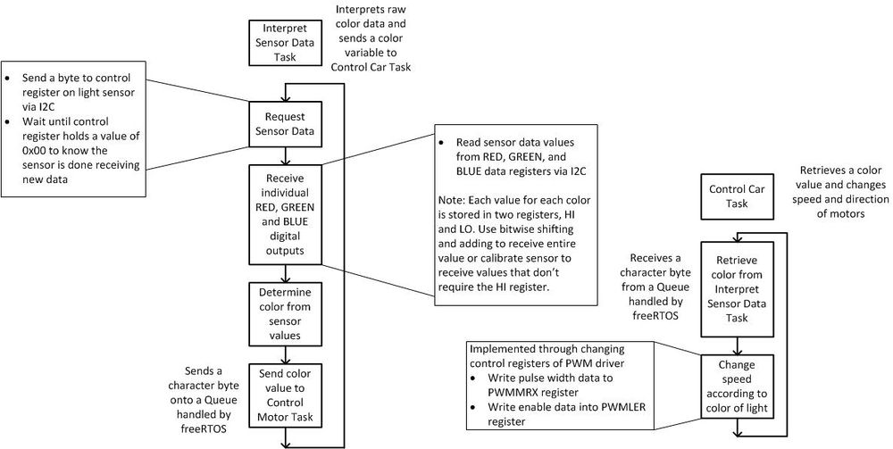
Psuedocode for Primary Functions
- Retrieving a RGB color value from sensor
- write a ready signal 0x01 to device register CTRL via I2C write function to device's write address (0xE8)
- wait until read data from CTRL register is 0 using I2C read function from device's read address (0xE8+1)
- write the data address value for the lower byte of a data register (eg. DATA_RED_LO is in register 0x40) via I2C write function to device write address
- read the value using I2C read function from device read address
- write the data address value for the upper byte of a data register (eg. DATA_RED_HI is in register 0x40) via I2C write function to device write address
- read the value using I2C read function from device read address
- shift the upper byte to the left by 8 (eg. upper = upper << 8;)
- add the upper and lower bytes together to obtain the integer data value
- Retrieving an Average value for sample size M
- retrieve a sample set of RGB values using code from above
- use a for loop M-1 times
- retrieve a separate set of RGB values
- add the two values together and divide by 2
- Sending data from sensor task to car control task -- We implemented this utilizing freeRTOS's queue structure
- in the main program, create a queue using freeRTOS's create queue function (xQueueCreate)
- after retrieving a set of sample data interpret what that color is -- this is done by taking sample data while the sensor is exposed to different colors of light and comparing the differences. This is probably the most difficult part of using the sensor
- send a character to the queue for the data collected using freeRTOS's send to queue function (xQueueSend)
- Retrieving data from sensor task
- retrieve a character from queue using freeRTOS's read from queue function (xQueueRead)
- Controlling motor direction and speed
- Direction
- controlled by a single I/O pin
- use CPU's IOSET function to indicate forward direction
- use CPU's IOCLR function to indicate reverse direction
- Speed
- controlled by PWM's match register (PWMMRX) and latch enable register (PWMLER)
- the frequency of the PWM signal is orignally set by writing a value to PWMMR0
- to change the speed of the motor write a fraction of the value in PWMMR0 to PWMMRX - the closer the number is to 0 the faster the speed will be (this actually changes the pulse width of the PWM signal)
- to enable the change, write the PWM pin number to PWMLER
- Direction
Hardware
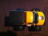
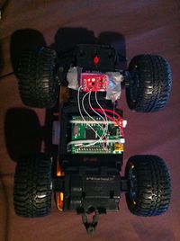
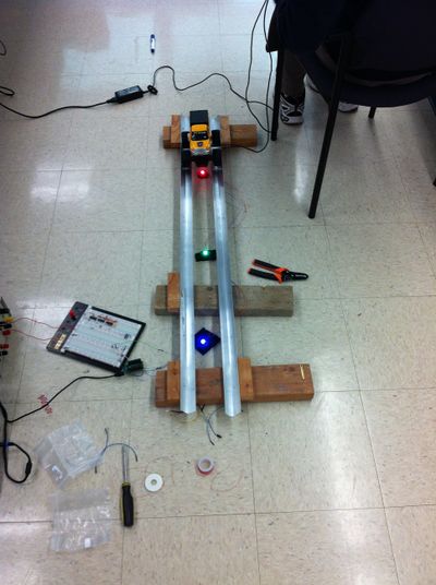
This section will provide pictures of hardware implementation of the vehicle.
Testing & Technical Challenges
The main challenge of this project deals with retrieving reliable readings from the color sensor module. The readings from the color sensor were inconsistent and extremely sensitive to environment changes.
Factors that affect color sensor:
- ambient light
- position with respect to light source
- distance from light source
To deal with the inconsistency and data fluctuations of the light sensors, we took an average of multiple readings. This, however, does slow down the data capture rate so the car was programmed to move more slowly to compensate. To ensure valid readings from the light sensor it would be advisable to isolate the light being captured. This method produces more consistent data, but takes away from the features of the application of light sensors on vehicles.
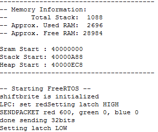
To test our project, we tested everything individually as we built them. Testing of each module took place using the UART communication with the microcontroller and our computer. Using Hercules, a utility with a serial port terminal, we sent commands from our computers to the microcontroller to control our drivers and tasks. Testing the light sensor took the longest amount of time and consisted of measuring values repeatedly to observe the values at different colors and different settings.
Due to the level of inconsistency of the light sensor, testing the final product was extremely inefficient. Because the car is continually taking data while moving, the positions of the light source with respect to the sensor will always be different. This results in different RGB data values on each run. This becomes difficult to handle when multiple colors of light come into play as distinguishing between colors will require comparisons of RGB values.
If we were to do this project again, we would try to calibrate the sensor to be more accurate. We could also try to use the second feature of the light sensor, reflective object measurement, where sensor evaluation board lights up white LED against an object to try and detect reflected rays of light.
Conclusion
In conclusion, this project has been an excellent experience for us. We were able to interface and use our own hardwares. Using the knowledge from the laboratory throughout the semester, we were able to accomplish the main goal. There were still some imperfection in our final performance. In order to improve this, more accurate reading from the sensor is essential. Calibration is the key for our project. We did not succeed in perfectly calibrating our sensor, thus lead to the varied data outputs. There is still room for improvement in the future. Our group appreciated the opportunity to experiment a hand-on Embedded System design project. We would recommend this project to future CmpE146 student since the idea is interesting, fun to work with, and yields satisfying result. However, early planning is a MUST and researching in advance can help boost up the process immensely.
References
Acknowledgement
Dr. Haluk Ozemek
Preet Kang
References Used
ADJD-S311-CR999 Light Sensor Datasheet and sample code: [7]
ADJD-S311-CR999 Light Sensor Application Note: [8]
ShiftBrite Documentation: [9]

