Project Advising: Remote Security System
Contents
- 1 Remote Security System
- 2 Abstract
- 3 Objectives & Introduction
- 4 Team Members & Responsibilities
- 5 Schedule
- 6 Parts List & Cost
- 7 Design & Implementation
- 8 Testing & Technical Challenges
- 9 Conclusion
- 10 References
Remote Security System
Abstract
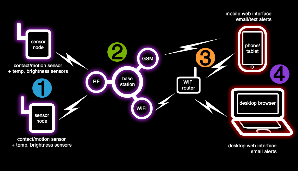
The objective of this project is to create a security system designed for homes and small businesses. The system will be comprised of a base station, low-power sensor nodes, a web application, and a mobile application. The base station will receive wireless transmissions from sensor nodes and notify the user of suspicious activity via text alerts. The user will be able to use a web or mobile application to view security reports and change settings remotely.
Objectives & Introduction
Traditional security systems are expensive, requiring a costly installation and an exorbitant monthly fee. These costs can be prohibitive to both small business owners and homeowners, who both have limited resources to dedicate to a security system. By replacing wired sensors with user-installable wireless sensors, the cost of a professional installation can be eliminated. By substituting a call center with text alerts and a cross-device web application, monthly fees can be eliminated and security can be placed into the property owner's hands.
The result of this project will be a working prototype of a wireless security system that accomplishes the following objectives:
Base Station
- The base station shall communicate wirelessly with sensor nodes
- The base station shall host a web app that can be accessed to configure the system and display logs and statues
- The base station shall send alerts containing suspicious activity via email
- The base station shall send alerts via SMS under circumstances where email is inaccessible
- The base station shall be capable of running off a backup battery when external power is lost
Sensor Nodes
- Sensor nodes shall be small, low cost, low power, and built using custom PCBs
- Sensor nodes shall be capable of being interfaced with a variety of sensors, including temperature, brightness, contact, and motion sensors
- Sensor nodes shall be configurable with different sensors
User Application
- The web and mobile application shall be used to configure the sensor configuration and settings
- The web and mobile application shall be used to view system logs and statuses
Team Members & Responsibilities
- Caleb Chow
- Sensor node (PCB, enclosure, sensors interface, software), Android app, and web app
- Warren Ou
- Sensor node (PCB, enclosure, sensors interface, software) and web app
- Christopher Pauley
- Base station (Raspberry Pi bring-up, Nordic module interface, communication with sensor node, web app)
Schedule
The following is the schedule beginning at the implementation phase of the project:
| Week # | Date | Task | Actual |
|---|---|---|---|
| 1 | 1/20 |
|
|
| 2 | 1/27 |
|
|
| 3 | 2/3 |
|
|
| 4 | 2/10 |
|
|
| 5 | 2/17 |
|
|
| 6 | 2/24 |
|
|
| 7 | 3/3 |
|
|
| 8 | 3/10 |
|
|
| 9 | 3/17 |
|
|
| 10 | 3/24 |
|
|
| 11 | 3/31 |
|
|
| 12 | 4/7 |
|
|
| 13 | 4/14 |
|
|
| 14 | 4/21 |
|
|
| 15 | 4/28 |
|
|
| 16 | 5/5 |
|
|
Parts List & Cost
Base Station
| Part | Quantity | Cost | Description |
|---|---|---|---|
| Raspberry Pi | 1 | $40 |
|
| SIM900 GSM/GPRS Module | 1 | $35 |
|
| SIM Card | 1 | $0 |
|
| Nordic Wireless Module | 1 | $20 |
|
| Battery Pack | 1 | $20 |
|
| Enclosure | 1 | $3 |
|
| Wireless Router | 1 | - |
|
| Total | $118 | ||
Sensor Nodes
| Part | Quantity | Cost | Description |
|---|---|---|---|
| Sensor Node Development Board | 5 | $400 |
|
| Contact Sensor | 2 | $15 |
|
| Motion Sensor | 2 | $26 |
|
| Battery | 2 | $18 |
|
| Enclosure | 2 | $7 |
|
| Total | $466 | ||
Design & Implementation
Hardware Design
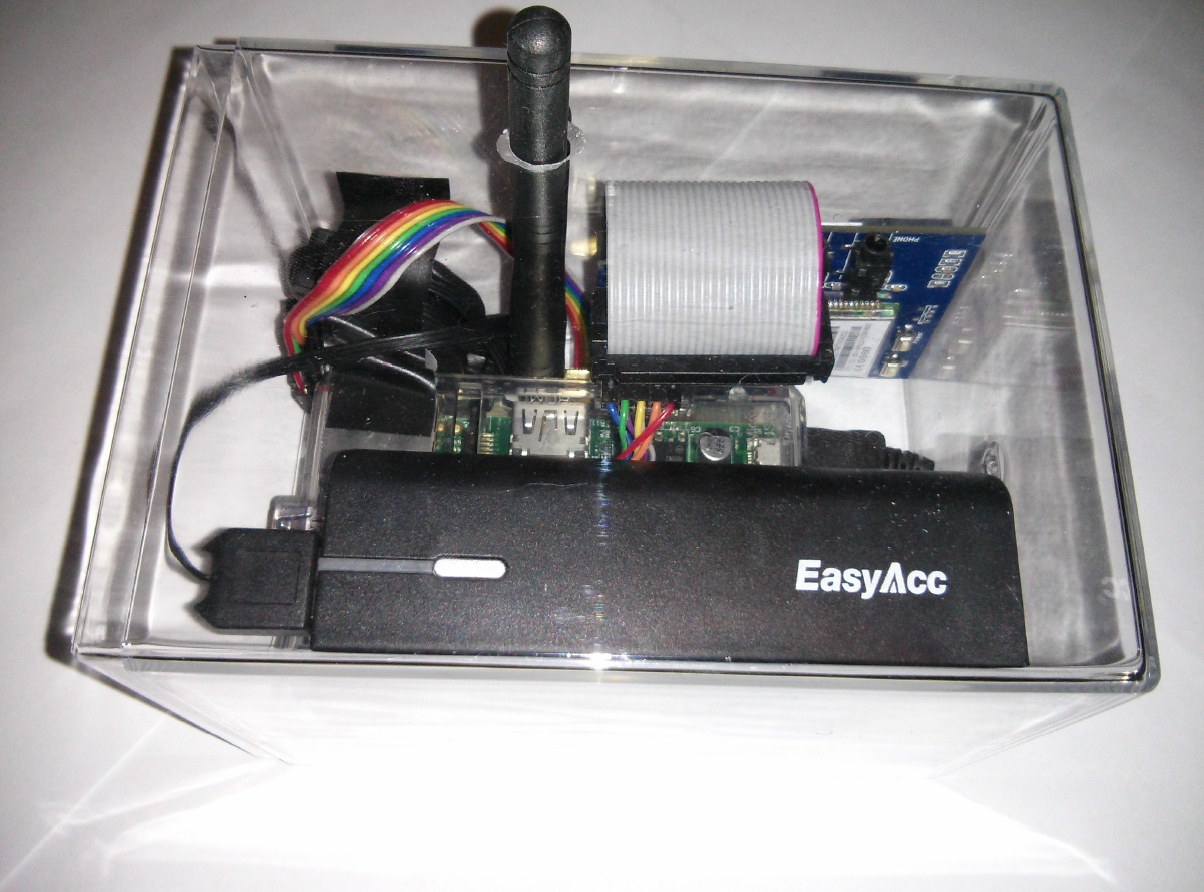
The hardware for the security system consists of two sub-systems. One sub-system is the wireless base station, which is based around a Raspberry Pi computer. The other sub-system is the wireless sensor nodes, which are based around an ARM Cortex-M3 microcontroller.
Base Station
The Raspberry Pi needed additional hardware to serve as the base station. The base station must be able to communicate with sensor nodes, communicate externally when the internet is down, and be capable of operating during a power outage. Considerations for the base station hardware are described below.
Sensor Node Communication
The Nordic nRF24L01+ wireless module is selected for its considerable range, low-cost, and energy efficiency.
Cellular Communication
The SIM900 GSM/GPRS module allows the base station to send text messages directly through a cellular provider. This is useful in cases where the internet connection or email service is unavailable.
Backup Battery
To accommodate cases where there is a power outage, a backup battery is included so that logging and external communication will still achievable. The base station runs off a USB battery pack with pass through capability so that the base station can seamlessly switch over to battery power when external power is unavailable.
Sensor Nodes
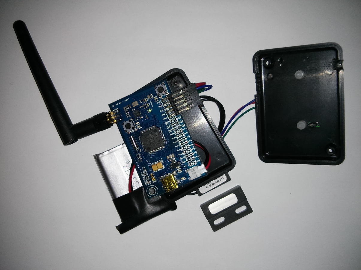
In order to create a small, low-power sensor node, the board is custom-designed around an ARM Cortex-M3 microcontroller based on the SJ One board. There are a number of design considerations that must be made to deliver a system that can be installed in the user's home or office with minimal impact. The sensors need to be small and unobtrusive, and require minimal maintenance, so energy consumption must be cut to a minimum to reduce the frequency of changing the battery. Considerations for the sensor node hardware are described below.
Battery Life
To maximize battery life of the sensor node, a custom PCB is designed based off the original SJ One board to reduce current draw from components. Pull-up and pull-down resistors are increased to reduce current draw and unnecessary components are removed. The following components are eliminated for the sake of improving battery life:
- Accelerometer
- Flash module
- IR receiver
- 7-segment LED display
- Buttons
- LEDs
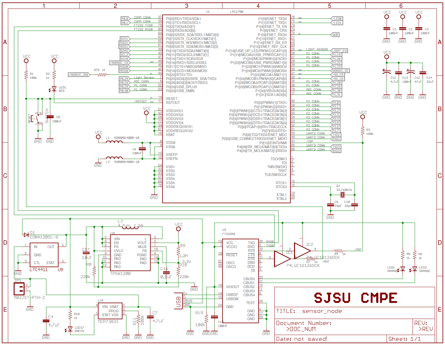
The USB UART IC, along with its TX and RX status LEDs are also designed to not be powered when running off battery. This requires additional logic to disconnect the components from the circuit when not being powered through USB. A boost regulator is also included to so that the full capacity of the 3.7V battery can be utilized. The boost regulator is necessary due to the board requiring 3.3V. Once the battery drops below the level required by the 3.3V regulator requires, the sensor node will die. But, the battery is still capable of supplying power down to 2.9V. The boost regulator ensures that the full output range of the battery can be utilized. An additional ideal diode is utilized to eliminate the extra voltage drop from a standard diode in the battery circuitry. This reduces the amount of voltage the boost regulator boost so that the system will function.
Size
The original SJ One board is also larger than necessary for a simple wireless sensor node, and by redesigning the PCB and eliminating components, the footprint can be shrunken down to fit inside a gum-sized Altoids tin. In additional to the components removed to improve battery life, the footprint for a XBee or WiFly module is also removed to reduce the size by a considerable amount.
Base Station Communication
The Nordic nRF24L01+ wireless module is selected for its considerable range, low-cost, and energy efficiency.
Convenience
The PCB is designed to be powered off a standard 3.7V lithium ion battery, which can be easily replaced when it no longer holds a charge. For the user's convenience, the battery can be charged using on-board charging circuitry by plugging in the USB.
Sensors
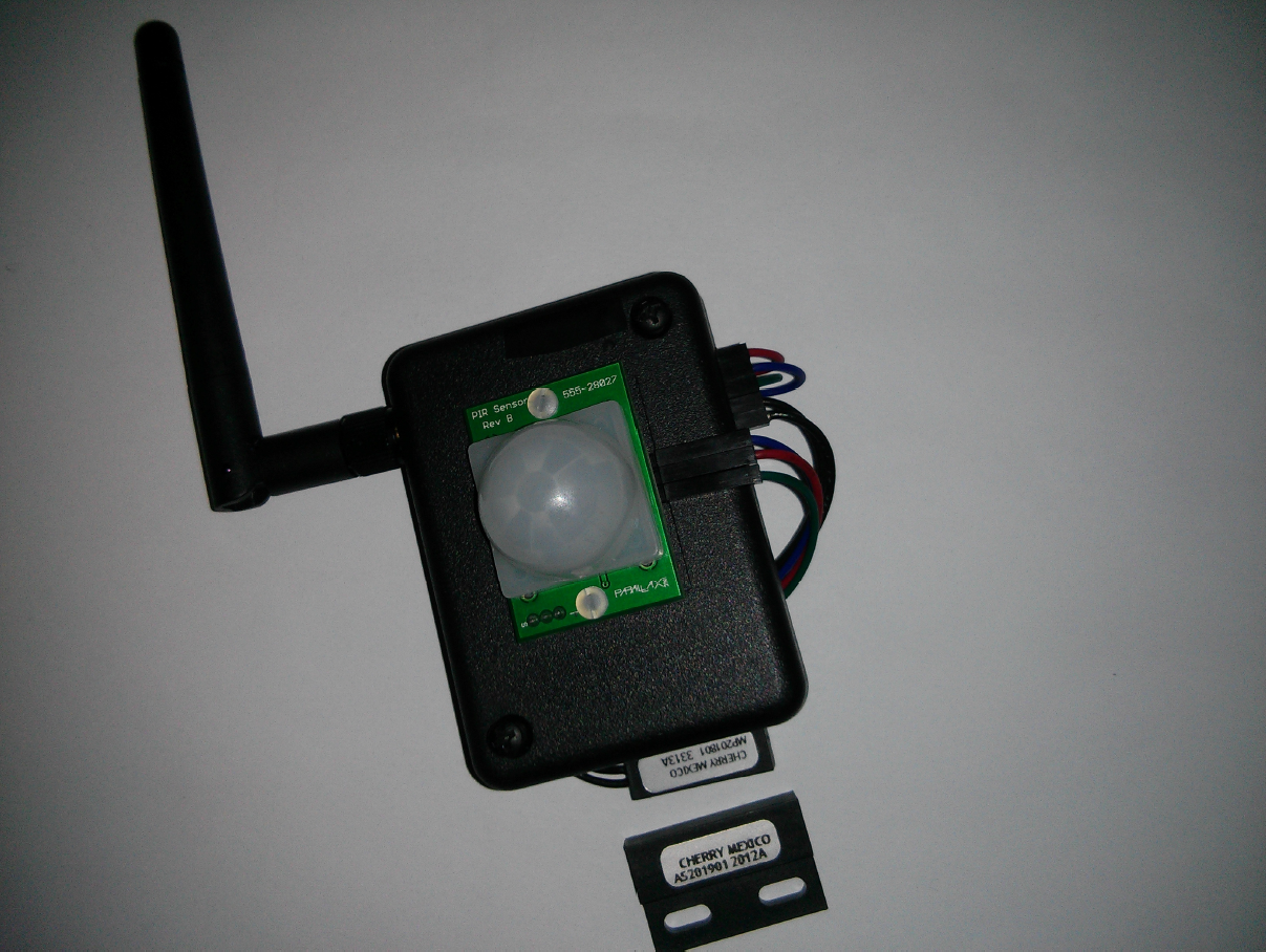
Contact and motion sensors are capable of being interfaced to sensor nodes, if the system configuration demands for it. These sensors are the core of the system to determine if there is a security issue.
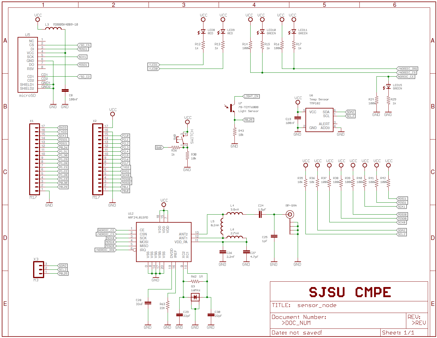
The schematics for the custom designed sensor node PCB are shown below.
Hardware Interface
Aside from the hardware interfaces on the sensor node, which is derived from the SJ One board, there are four hardware interfaces which need to be designed for the system:
- SPI interface between the Raspberry Pi base station and the Nordic wireless nRF24L01+ module
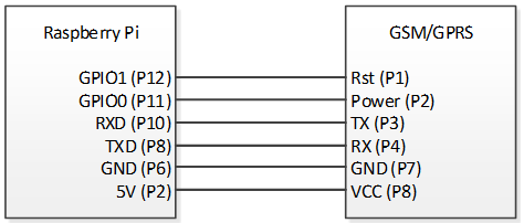
- UART interface between the base station and the GSM/GPRS module
- Contact sensor for sensor node
- Motion sensor for sensor node
Raspberry Pi to Nordic Wireless Module
Raspberry Pi to SIM900 GSM/GPRS Module
Sensor Node to Contact Sensor
Sensor Node to Motion Sensor
Software Design
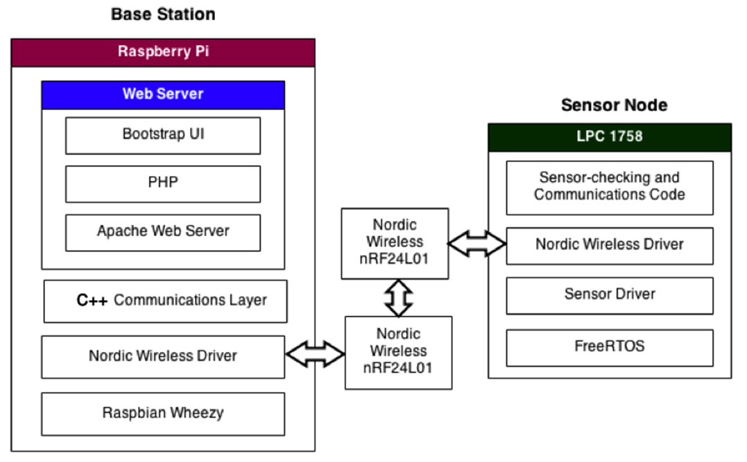
The system software is divided into two parts: the base station and the sensor node. The software design for the entire system is shown below.
Base Station
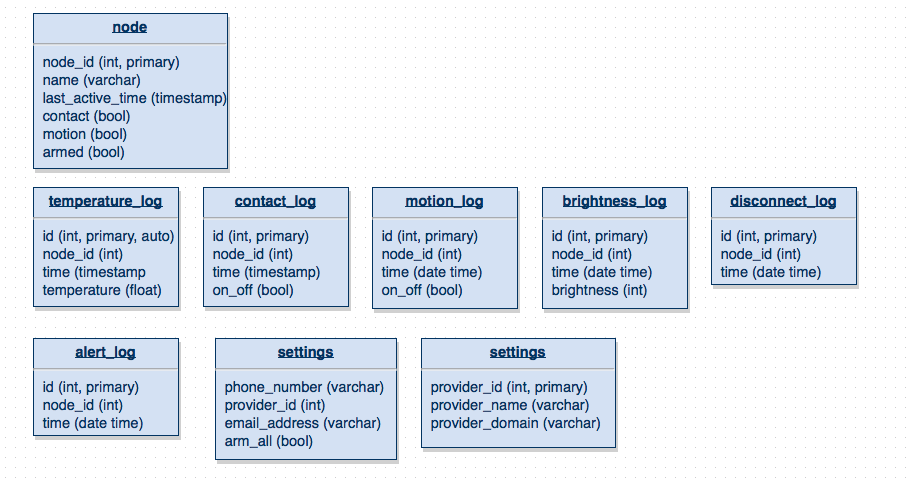
Database
The base station must store and process data sent from the wireless sensors, so there must be a mechanism for storing all this data. The most logical choice is a MySQL database to store information from the sensors. The communications code on the base station will use a C++ driver for the Nordic wireless nRF24L01+ module and accessed using PHP.
Communication Protocol
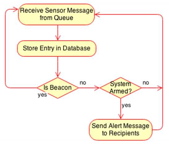
Communication between the sensor nodes and base station are achieved with the following steps:
- Sensor node sends a packet
- Base station receives data, logs it in the database, and triggers alert if node is armed
Logging and Notification
Once the base station receives a packet from a sensor node, the data has to be logged. Notification may also be sent depending on the system state. A process running in the background is also used to determine if additional alerts are necessary, in the case where missing packets signify a node being unavailable.
External Interface
The system is accessed solely by the web application on the base station. Through the web application, the user can setup the system and configure the system to send notification upon a sensor being triggered. The mobile application utilizes this web application to access the system.
User Interface
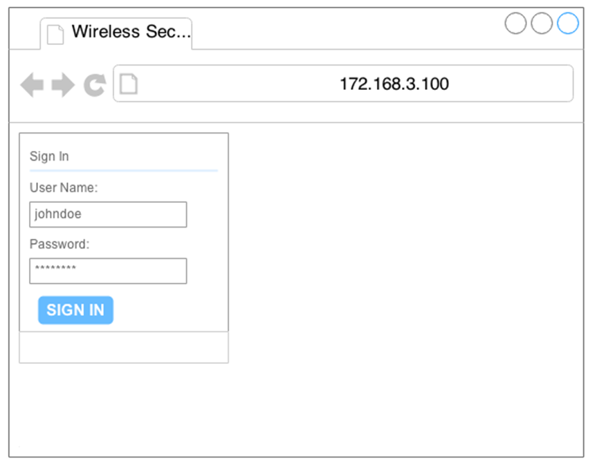
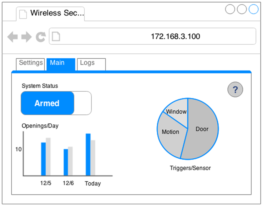
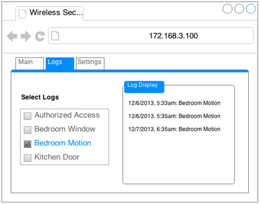
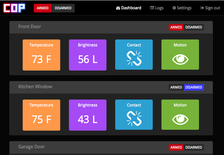
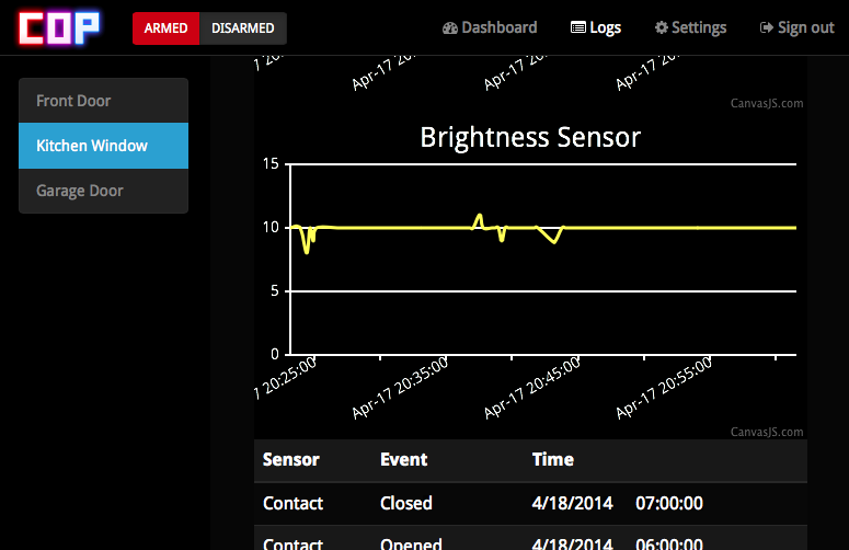
The user-interface is designed around Bootstrap, an HTML framework. The basic pages for the web-interface are shown below.
Sensor Nodes
Communication Protocol
Communication between the sensor nodes and base station are achieved with the following steps:
- Sensor node detects sensor status changed
- Sensor node sends data through Nordic module to the base station
- If no activity within preset time, send beacon message packet through Nordic module
Detection and Transmission Tasks
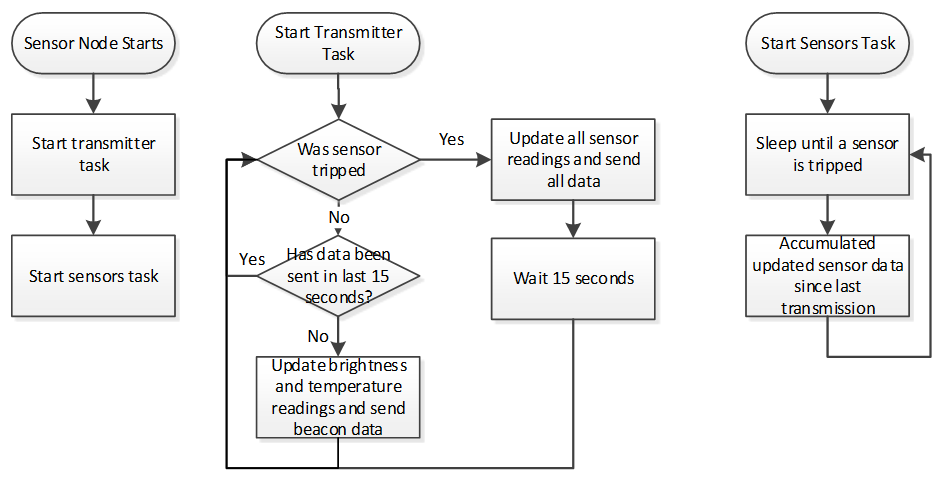
The sensor nodes run two tasks, a sensors task and a transmitter task. The operation of the two tasks are shown in the diagram below. The sensor node will send data to the base station whenever a sensor goes from one state to another. When the sensor has not been triggered for a certain set time period, a beacon message will be sent to notify that the sensor node is still alive.
Hardware Implementation
Base Station
Sensor Nodes
Software Implementation
Base Station
Operating System
To program the Raspberry Pi, it is necessary to load a Linux distribution on an SD card. The base station would be well suited with the popular Raspbian, as it is the most commonly used distribution and there are abundant resources for setting up common communication protocols and web services.
SSH and Remote File Access
In order to develop on the Raspberry Pi without being chained to an HDMI monitor, it was necessary to configure SSH. With SSH, it is possible to operate the Raspberry Pi from the command line, and with Unix, or Mac OSX (which runs Unix) a graphical interface can be opened as well. To increase efficiency in programming on the Raspberry Pi, it was necessary to seek out a solution for managing files on the development laptop. Two options were used for accessing files remotely, an FTP server and SSHFS. FTP allows remote access to files through popular FTP clients. SSHFS goes a step further with Mac OSX, and allows the developer to mount the Raspberry Pi over SSH and edit files seemingly locally, using whatever text editor to save files [1].
Internet Sharing
In order for the Raspberry Pi to be able to access the internet, it is necessary to enable internet sharing on the development laptop. By properly configuring internet sharing and IP settings, the Raspberry Pi is able to access the internet without access to a router [2].
SPI Setup
There is an option in the "raspi-config" command that turns on SPI capability, but in practice it doesn't work. The solution is to enable SPI by updating the firmware with Hexxeh's firmware update tool. Once the developer runs the tool on the Raspberry Pi, the SPI devices spi0 and spi1 show up in the /dev folder [3].
LAMP Setup
For the web GUI, it is necessary to install a web server, MySQL and PHP. This is generally referred to as LAMP: Linux, Apache, MySQL and PHP. It was necessary to install these tools with apt-get, also installing the Apache-PHP module to enable PHP to work with Apache [4].
sSMTP Setup
To allow sending a text message from the Raspberry Pi base station, sSMTP is utilized along with mail utilities. Both of these tools are installed using apt-get. Afterwards, the sSMTP configuration files are modified to include an existing Gmail account to forward the text messages to the user's phone [5].
Nordic to Raspberry Pi Interface
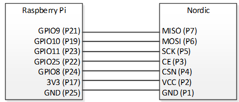
To enable communication between the Raspberry Pi and the Nordic nRF24L01+, it was necessary to install a third-party driver to enable communication. Stanley Seow's RF24 library provides a full set of commands to enable communication with the Nordic nRF24L01+. Once the pins were properly connected, the first test was sending a message from one Raspberry Pi to another [6].
The library provides sample code for receiving messages and sending them back, and the code was modified to send a basic message from one Raspberry Pi to another. Once Pi to Pi communication was established, the Nordic had to be configured to communicate with the completely different driver running on the sensor node. There were a number of register values on the Raspberry Pi's nRF24L01+ that had to be modified to enable communication including auto ACK being disable and matching the pipe addresses.
Logging
Logging is kept in a local MySQL database. The database stores Node ID numbers along with readings from the temperature sensor, motion sensor, light sensor, door sensor, and a timestamp. The database is accessed through the main security program in C.
Security Program
The main security program consists of a hub that receives messages from any sensor nodes. Upon receiving a packet, the packet is parsed and the information is stored into the MySQL database. An acknowledgement packet is sent back to the node so repeated packets will not be sent. If any intrusions are detected a PHP script is called to alert the owner. In order to increase the security of the system, data acknowledgement was implemented. To enhance security even further, a background daemon is used to occasionally detect if a sensor node is disconnected. Upon detection, an alert is also sent.
SMS/Email Alerts
In this set up, an existing Gmail account is used with sSMTP to forward messages to a cell phone's texting email address. The cell phone's email address is defined by its carrier (e.g. AT&T numbers have an email address in the form of: [10 digit number]@txt.att.com). The owner selects which numbers and emails to send messages to. When an intrusion is detected, the main security program calls a PHP script which sends a message out to the numbers selected. In case of trouble with internet access or power outage of an access point, the base station also includes a GSM/GPRS module for texting with a SIM card. When internet connectivity is not detected, the base station uses this module to inform the owner of any intrusions.
User Interface
To enable users to view the status of and control their security system, it is necessary to have a slick, modern web GUI. Bootstrap was chosen to provide a cross-browser, responsive GUI design, meaning that the web interface looks the same on mobile devices as it does on a computer monitor. Graphing capability is provided Google Charts, a Google API for plotting and graphing data on a variety of graph types.
Sensor Nodes
Nordic Wireless Driver Setup
The driver for the Nordic module was based off Preetpal Kang's library in the sample project for the SJ One board.
Sensors
To read the value of the sensors, GPIO pins were used. Both the contact and motion sensor used GPIO pins.
The contact sensor was configured and read with the following steps:
- Configure one input pin with pull-down and interrupts enabled for one terminal of sensor
- Configure one output pin to high (or tie to 3.3V) for other terminal of sensor
- When edge interrupt triggered, if high then contact, else no contact
- If sensor gets disconnected, sensor reads no contact
The motion sensor was configured and read with the following steps:
- Configure one input pin with pull-up and interrupts enabled
- When edge interrupt triggered, if high then motion, else no motion
- If sensor gets disconnected, system reads motion
Security Program
Using FreeRTOS, the sensor nodes send sensor readings to the base station. Acknowledgements from the base station are received to notify that the transfer was successful.
Testing & Technical Challenges
The base station and sensor node were unit tested before integration. The entire system was tested after integration to ensure that the system was functional.
The following criteria were tested:
- Sensor Node Test
- Sensors get triggered
- Detects when to send status updates to base station
- Base Station Test
- Web app is accessible
- Sign in functional
- System can be armed/disarmed only with log in
- Displays sample test data
- Scheduler and notifications are functional
- Overall System Integration Test
- Sensor node can be paired
- Base station receives sensor data and status updates
- Sensor triggers notification when armed
The main challenges faced in the project were in the PCB design and wireless communication. The creation of the PCB only allowed for one try due to time and money constraints. Although the design is based off an existing proven design, the modifications made were enough to cause issues. A poor PCB manufacturer caused even more issues as many of the boards were broken. Wireless communication was also an issue as an incorrect configuration resulted in no communication.
Sensor Node PCB
During the design phase, the sensor node was designed to have a low power consumption. Pull-up and pull-down resistors were increased to reduce the amount of current drawn. One pull-down resistor on the battery charging circuit was modified from 2kΩ to 100kΩ. This inadvertently limited the charge current to almost nothing. A lower value 4k7Ω resistor was used to replace the charge current limiting resistor to resolve this issue and keep the charge time reasonable.
The board was re-designed such that it could operate off a 3.7V lithium ion battery. To accomplish this, more logic had to be added to the FT232 module. The issue faced was that the FT232 needed to be powered off 5V in order to not keep the CPU in the reset state. Tri-state buffers were added to disconnect the FT232 from the CPU when it was not powered. But, the signal selected to determine if the FT232 was powered was flawed in that the signal did not behave as expected. The selected 3.3V out signal on the module was floating when the chip was not powered, even with a pull-down resistor. This was unexpected and caused the board to be stuck in reset mode when started up off the battery. To resolve this, the USB cable must be plugged in to get the FT232 to no longer be in a reset state. In the next revision, the input to the tri-state buffers will need to be modified. The source could be changed, possibly to the 5V on the USB port. In the prototype, the resistor from the DTR line of the FT232 was removed such that the CPU would not be kept in the reset state. Manually pressing the reset button will be required to program the boards since the DRT line can no longer be controlled through software.
After the manufactured PCBs were received from OurPCB, they were tested to ensure that the boards were functional. Upon visual inspection, three out of the five boards were determined to be soldered improperly. There were shorts visible on components from the poor soldering job, especially on the Nordic, FT232, boost regulator, and CPU. A soldering iron was used to run over the connections to reflow the solder and remove the shorts. But even after repairs, the three boards would not boot. This is possibly due to the boards being burnt during testing. Of the two boards, one was fully functional and the other was unable to transmit at longer distances. The reduced transmission distance is possibly a result of a poor soldering job, as some of the components are not touching the PCB but is touching solder. A more reliable PCB supplier will be necessary for revisions.
Nordic Wireless Driver on Raspberry Pi
The most prominent issue in the entire project was getting the Raspberry Pi to communicate with the Nordic nRF24L01+. Once SPI was installed, it was tested by using a loopback script. Connections between the Raspberry Pi and the Nordic were carefully tested by setting each wire low and high and measuring with a multimeter. When the RF24 driver didn't work, it was attempted to write a driver from scratch, using simple SPI command to read the value of the Nordic's registers. What was thought to be a programming error on the developers' part was actually a documentation error made by the author of the driver, Stanley Seow [7].
While the SPI connections MOSI, MISO and SCLK were all correct, Stanley Seow made the mistake of writing that CE on the Pi should be tied to CE on the Nordic. Being the author of the driver, it made perfect sense. However, CE on the Raspberry Pi is a completely different function than CE on the Nordic. After further investigating the Raspberry Pi and Nordic documentation, it is learned that CE0 and CE1 on the Raspberry Pi are SPI chip select, but CE on the Nordic is actually a select line for choosing whether to put the device in Rx or Tx mode. However, being called "Chip Enable" it seemed to make sense that it would be tied to CE0 or CE1 on the Raspberry Pi. Instead, SPI chip select on the Raspberry Pi is actually called CSN. Swapping CE and CSN on the Nordic solved the issue, and the RF24 driver worked.
Conclusion
Wireless security systems are getting cheaper and putting more control into the property owner's hands, but there is a need for an unrestricted product without recurring costs. The wireless security system detailed by this paper is simple to manufacture, using a single PCB for each sensor and a pre-built development board for the base station. The resulting product detailed by the requirements is low-cost, flexible, and easy for any user to install. This security system has an easy to operate user-interface, with all the features available without charging the user any additional money per month. The custom-designed circuit and PCB for the sensor node allow precise control over power consumption. By cutting unnecessary components, further control of power consumption can be accomplished by utilizing microprocessor sleep states. Also, by using a Raspberry Pi the developer can rapidly set up a web server and deliver a dynamic control panel for the security system using the latest web content generation techniques. The end result is a hardware/software security system that is very easy to use, and provides maximum impact for the consumer's investment.
Project Video
Upload a video of your project and post the link here.
Project Source Code
Send me your zipped source code and I will upload this to SourceForge and link it for you.
References
Acknowledgement
We are deeply indebted to Preetpal Kang for his invaluable comments and assistance in the development of this prototyping project. We'd also like to thank Steven Yu for his advice and feedback in the PCB design process.
References Used
[1] Home: Fuse for OSX [Online]. Available: http://osxfuse.github.io
[2] Share your internet from your Macbook Pro Retina to your Raspberry Pi [Online]. Available: http://kmahelona.blogspot.com/2013/04/share-your-internet-from-yourmacbook.html
[3] Brian's Life: Getting SPI working on the Raspberry Pi [Online]. Available: http://www.brianhensley.net/2012/07/getting-spi-working-on-raspberry-pi.html
[4] RPi: A Simple Wheezy LAMP Install [Online]. Available: http://elinux.org/RPi_A_Simple_Wheezy_LAMP_install
[5] SMTP Mail Setup [Online]. Available: http://rpi.tnet.com/project/faqs/smtp
[6] Setup Nordic nRF24L01 RF modules to both Arduino UNO and Raspberry Pi [Online]. Available: http://arduino-for-beginners.blogspot.com/2013/02/setup-nordic-nrf24l01-rfmodules-to.html
[7] stanleyseow/RF24 [Online]. Available: http://github.com/stanleyseow/RF24

