F21: Skeh-lleybones
Contents
Block Breaker
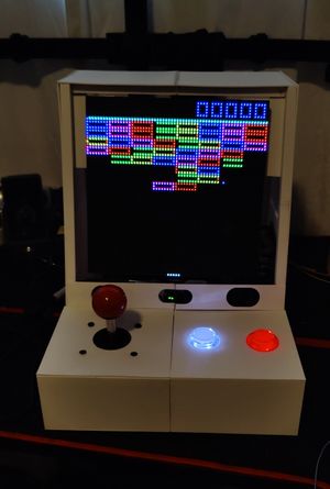
Block Breaker is a fun game in which you control a paddle and destroy blocks with a moving ball. The player controlled paddle deflects the ball at different angles to target different blocks and destroy them.
Abstract
As the capstone project for this class, we were instructed to create a video game using a few required elements. As the cornerstone of development in this class, we were required to use the SJ2 development board. Additionally, we were required to use a LED matrix as means of displaying the video game movement. Finally, we were required to facilitate the usage of an external peripheral or sensor that would contribute to the end result in a meaningful way.
Introduction
In order to realize the requirements of this project, we constructed a plan to verbally prototype a few different elements of the project:
- The idea of the game - we discussed two player snake as a potential idea, but ultimately decided on block breaker.
- The task logic - it made sense to run a single task that would serve as the "clock" task to operate the game at a stable refresh rate. Another task could serve to update the data structure that held the state of the LED matrix at any given moment in time.
- The LED matrix driver - because of the nature of the LED matrix's operation, a consistent order of operations is required to update each pixel. More on this will be discussed in later sections.
- The enclosure - since we had access to a 3D printer, we concluded that a tabletop arcade cabinet would serve to house all necessary components.
- The music - we decided to use the theme song from the video game Geometry Dash since we used rectangular blocks and doing so pull us in scope of using the theme song.
Objectives & Introduction
In order to accomplish the objective of the game, we split the project into a few sub-topics that could be tackled individually:
- Main "clock" task for updating the LED matrix.
- Main gameplay loop task that would update the position of the ball, paddle, and blocks.
- Design of various game screens via a state machine.
- Game logic to determine the ball's bounce relative to its current trajectory.
- Design of PCB to utilize a ground plane and avoid excessive loose wiring.
- Design of a 3D printed enclosure to display a clean look.
- MP3 background track during gameplay.
- Speaker volume adjustment based on user proximity to enclosure.
Team Members & Responsibilities
Prabjyot Obhi
- Core MP3 module driver development.
- Task logic for sending music data to MP3 module.
Justin Stokes
- Core game logic development.
- Debugging and testing of game logic and LED Matrix functionalities.
Manas Abhyankar
- Develop LED Matrix driver.
- Design and print enclosure for project.
- Design and send PCB for manufacturing.
Schedule
| Week# | Start Date | End Date | Task | Status |
|---|---|---|---|---|
| 1 |
|
|
|
|
| 2 |
|
|
|
|
| 3 |
|
|
|
|
| 4 |
|
|
|
|
| 5 |
|
|
|
|
| 6 |
|
|
|
|
| 7 |
|
|
|
|
| 8 |
|
|
|
|
| 9 |
|
|
|
|
Parts List & Cost
| Part | Link | Price | Quantity |
|---|---|---|---|
| LED Matrix | Sparkfun | $80 | 1 |
| Power Supply | Adafruit | $30 | 1 |
| Barreljack connector | Adafruit | $0.95 | 1 |
| Joystick | Sparkfun | $16.95 | 1 |
| Button | Adafruit | $2.50 | 2 |
| Quick connect wires | Adafruit | $4.95 | 1 |
| Resistors/Capacitors | N/A | N/A | 3 of each |
| Ultrasonic Sensor | Adafruit | $3.95 | 1 |
| MP3 Module | Adafruit | $34.95 | 1 |
| Speakers | Adafruit | $7.50 | 1 |
| 3D Printed Enclosure | To be 3D printed | N/A | 1 |
| 40-pin ribbon cable | Adafruit | $2.95 | 2 |
| SJ2 Development Board | Amazon | $50 | 2 |
Design & Implementation
The design section can go over your hardware and software design. Organize this section using sub-sections that go over your design and implementation.
Hardware Design
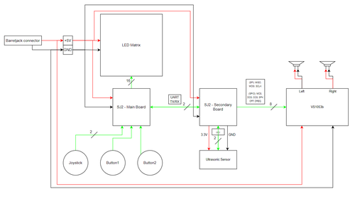
In the hardware setup for this project, we listed a few high-level conceptualizations of what connections must be made. These conceptualization can be viewed in the top-level schematic show below this list. It was designed used draw.io.
- SJ2 Interconnect
- SJ2 connection to LED matrix
- SJ2 connection to VS1053b
- SJ2 connection to ultrasonic sensor, buttons, joysticks
For our implementation, we decided to use two SJ2 boards: one controlled the game logic and drove the LED matrix, the second controlled the music track. The SJ2 interconnect would enable the SJ2 boards to communicate with each other. Doing so was important so that the appropriate sound effects could be played when specific game events occurred. Unfortunately due to time constraints, we were unable to make use of this SJ2 interconnect.
For the first board, it was responsible for game logic and driving the LED matrix. The matrix required a variety of pins to connect them to the SJ2. It did not use any standard peripheral for communication (such as I2C or UART) so the pins were driven using GPIO switching. The pins used are listed below:
| Address Pins | Color Pins | Control Pins |
|---|---|---|
| A, B, C, D, E | R2, G2, B2 | OE, CLK, LAT |
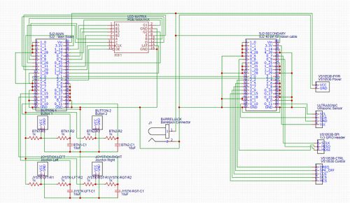
The color pins enabled 8 different colors through various combinations of red, green, and blue. The address pins allowed us to select a specific row for updating its pixels from values 0 - 31. Finally, the control pins were used to latch in row and pixel data and to enable or display the output. More about these control pins will be discussed in a coming section. The mapping for these pins can be found in the hardware schematic below.
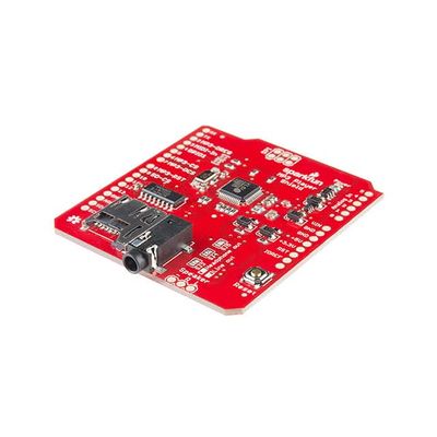
The next interconnect to be discussed is for the VS1053b music decoder. Its exact pin connections will be shown in a later section. It utilized the FatFS library to send bytes of music data over SPI for communication with the music SJ2 board. The VS1053b can utilize two screw terminal blocks to connect to external speakers, or a 3.5mm audio jack can be used to connect to desktop speakers or headphones. This board also used the ultrasonic sensor to play and pause the music. The ultrasonic
The final connection that was made connected the buttons and joystick to the main SJ2 board. The buttons were configured in a falling edge interrupt setup, with a button press causing a falling-edge interrupt that was handled with a software ISR. The joystick was configured to perform an action on a polling setup so that holding the joystick in a direction would continuously move the paddle in the game.
The hardware schematic shown below was designed in EasyEDA and shows all of the connections made between all of the components.
Hardware Interface
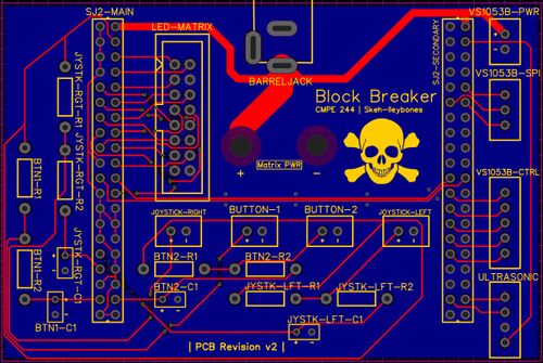
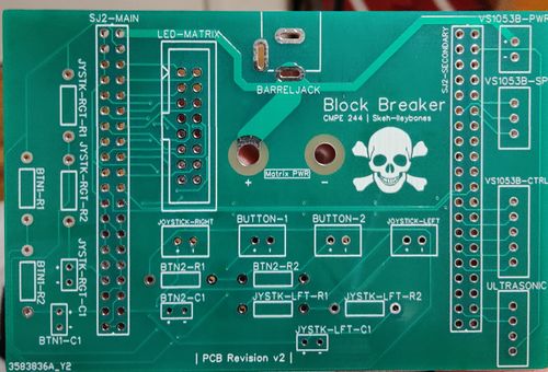
Since we had two different SJ2 boards and various other components, we required a PCB to consolidate all of the necessary connections. Using EasyEDA, we developed a PCB that would connect all of the components together. The pictures below show the final result.
To enabled the interboard communication, we decided to simply use UART. We deduced that it would be fast enough to transmit signals to the music board to play specific sounds when a block was struck or when the ball bounced. All of the LED matrix connections were made as short as possible to the main board to eliminate any chance of crosstalk affecting the quality of the LED matrix image. The buttons and joystick were connected to a few GPIO pins, 2 of which were configured for GPIO interrupts on GPIO Port 0 for the buttons, and the other 2 which were configured for polling using different GPIO pins. These pins were all attached to a debouncing circuit that used 1kOhm resistors and 10uF capacitors. We found that this combination was optimal considering our supply of existing components and the desired RC time constant. On the music board, the SJ2 connected to the VS1053b using GPIO connections and utilized SPI for data transfer between the song stored on the SD card and the decoder.
One of most important aspects of a PCB is to have a ground plane. This entails have a solid copper pour-over as a single layer of the PCB to encourage limited trace crosstalk and noise immunity. In our first rendition of the PCB, we failed to incorporate this practice and suffered from a myriad of noise, affecting signal integrity of the LED matrix connections. Our second rendition fixed this by creating a ground plane on the bottom layer of the PCB and routing signal and power traces through the top layer. Additionally, we opted to use a barreljack connector to distribute power to everything attached to the PCB. This enabled us to connect everything to the same PCB, making for a compact solution that fit within our 3D printed enclosure.
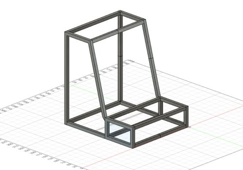
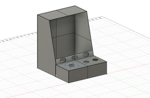
This leads us into the topic of the 3D printed enclosure. Since 3D printing has greatly matured in the past 5 years, designing a 3D model and printing was simple and a great learning experience. The concept of the 3D printed enclosure would let us capture all of our componentry in a single "box" that would be easy to transport and to setup. The back of the 3D printed enclosure was made detachable by means of a canvas sheet and velcro strips. The pictures below show the 3D printed enclosure's frame and panels.
Software Design
Below are the list of the tasks we used to create our project. This includes, the task name, task priority, and high-level view of what the task performed.
| Task Name | Task Priority | Comments |
|---|---|---|
| left_button_task | PRIORITY_HIGH | This task was used to receive inputs from the left button. Used interrupts to send binary semaphore on each press. |
| right_button_task | PRIORITY_HIGH | This task was used to receive inputs from the right button. Used interrupts to send binary semaphore on each press. |
| joystick_task | PRIORITY_MEDIUM | This task was used to monitor movement of the joystick. This task was polled rather than using interrupts |
| game_state_machine_task | PRIORITY_HIGH | Task responsible for running the game. Accessed the main state machine used to drive the game logic. |
| update_display_task | PRIORITY_HIGH | Updated the physical matrix based on the 2D array in code. |
| check_for_speed_up_task | PRIORITY_MEDIUM | Checked if the 'current power up' was a speed related power up. If yes, changed the delay of game_state_machine_task to reflect the speed up/down. |
LED Matrix Driver
The LED matrix is controlled with a specific set of instructions. It functions by updating 2 rows of LEDs at a time, 1 in the first 32 rows and 1 in the second 32 rows. This type of scanning pattern occurs at a high enough frequency such that the human eye is unable to perceive the "scanning line" effect. The GIF below illustrates this effect.
In order to update the LED rows, you must do the following:
- Disable the latch
- Enable the output (keep in mind this signal is active low)
- Use the RGB pins (R1, G2, etc) to set a color for a pixel in a row
- Give a clock pulse to latch in the selected colors for each pixel in the row
- Enable the latch to drive the LED driver
- Disable the output
The code in the following snippet will demonstrate the logic behind this functionality.
Below you can find the coded implementation used to drive the LED Matrix based on the control method described in the above section.
for (int i = 0; i < 32; i++) {
   led_driver__disable_latch();
   led_driver__enable_output();
   for (int j = 0; j < 64; j++) {
     led_driver__map_color_code_to_color_select_pins_top(led_matrix[i][j]);
     led_driver__map_color_code_to_color_select_pins_bottom(led_matrix[i + 32][j]);
     led_driver__clock_toggle();
   }
   led_driver__enable_latch();
   led_driver__disable_output();
   ((i)&0x01) ? gpio__set(A) : gpio__reset(A);
   ((i)&0x02) ? gpio__set(B) : gpio__reset(B);
   ((i)&0x04) ? gpio__set(C) : gpio__reset(C);
   ((i)&0x08) ? gpio__set(D) : gpio__reset(D);
   ((i)&0x10) ? gpio__set(E) : gpio__reset(E);
 }
}
Game Implementation
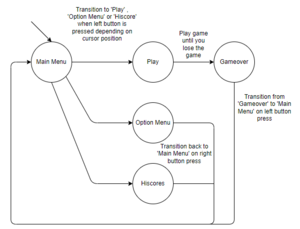
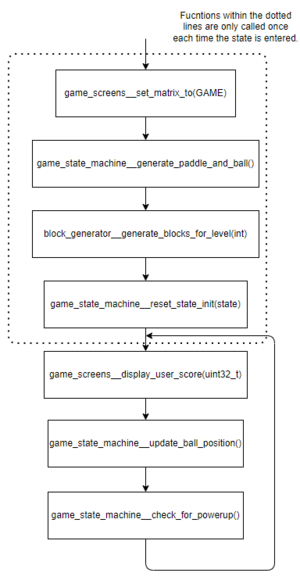
The game was implemented using a state machine. The main driving function, ‘game_state_machine__run_game()’ is outlined in the below flow chart( main_game_logic ). A state machine design was chosen for two reasons. First, states did not simply flow down from one state to the next as shown in the state transition diagram below. Using switch and case statements is also much easier from a code readability standpoint then a large if-else block.
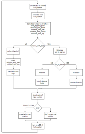
The above flow chart takes a look inside the 'GAME' or playing state at a high level. The functions that are called within the dotted box are only called once upon each state transition. This is done such that the main UI is initialized only once which greatly reduces the amount of data being written to our display buffer. We designed each module such that it only updates the part of the display it is affecting rather than simply rewriting the whole buffer. Most of the functions do exactly as their names suggest and aren't very in-depth besides game_state_machine__update_ball_position which is covered below.
The above flowchart goes over the majority of the logic required to run our game. Collisions with the top of the game area, left wall, right wall, paddle, and blocks are all calculated and acted upon here. First we calculate the next position of the ball as if there were no blocks. Based on this calculated position, we check for collision with any blocks by checking the current value of the coordinate in the matrix buffer. If there is a value other than zero, we know we have some sort of collision with one of the various objects within the game area. If it is not a block, then we simply handle the bounce logic based on the current direction the ball is travelling.
Once we decide if the collision is with a block, we then check if the current position of the ball is in the corner of two or more blocks. This is to decide how many blocks are hit in the case of being in a corner. If it is determined that the ball is not in a corner, we hit a block and handle the bounce logic. If the ball is in a corner, we hit up to three blocks then send the ball in the opposite direction from which it came. We also implemented the concept of block lives based on their color so one more check is required before updating the ball's position. this check involves the color of the LED in the expected next position. We expose an API from the LED Matrix driver which will return the current color at that position. If this is determined to be BLACK or CYAN, we update the position and light up the LED using CYAN. If not, then we do not update the ball position. If we did update the position, then the block(s) which were hit would then be missing a pixel at that location causing an issue with detecting collisions going forward.
Block lives were one of the features we decided to implement. This was tracked using the color of the block and keeping these colors in a block array. The colors of a block could be the following: RED, GREEN, YELLOW, BLUE, PURPLE. With RED meaning the block has one life left and PURPLE having five. When we hit a block we decrease the life by simply decrementing the index of that block based on the array. Scoring was implemented in the same function and we simply added 100 each time a block was either hit or deleted, depending on its color. Since we had scoring implemented, we also wanted to keep track of the hiscores to add a competitive aspect. A sorted five element array of scores was used to do so. Going forward, we would have wrote this to the SJ2's on board flash memory to have a persistent record rather than having a new list each time the game was powered on/off.
MP3 and Ultrasonic Hardware Design and Interface
The overall hardware design of the MP3 module was very straightforward as the means of communication between the SJ2 and the VS1053B board was an SPI interface. The MP3 control pins such as CS, DCS, DREQ, and RESET were simple GPIO pins that were available on the SJ2 board. The largest component was to select which GPIO pins and SPI interface to employ as everyone had to be consistent due to the fact that this would be connected onto a PCB. The thought process behind selecting pins to choose was the spacing between each grouping of pins as well the ease of putting wires in.
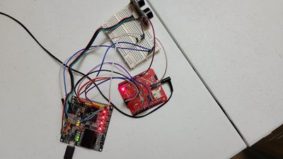
The pins that we decided to use for the MP3 control signals are as follows: DREQ to 2.2, RESET to 2.5, DCS to 2.7, and CS to 2.9. We chose these pins because they are in a straight line. Also, the MP3 pins are away from the SPI pins which are as follows: Clock to 0.7, MISO to 0.8, and MOSI to 0.9. Below are images of the VS1053B connected to the SJ2 Board
Once all of the wires were set up we had to use the 3.5-millimeter wire to connect the module to different speakers, headphones, and other audio devices to ensure that we could hear the music being played and that the quality of the sound was decent. This is shown below.
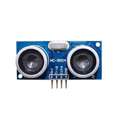
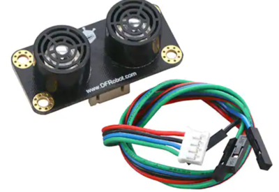
The final component was the ultrasonic sensor, and we initially used a spare $4 component. We quickly realized it would be easier to simply use a higher quality, better sensor for our project. Luckily, we were able to take apart a previous project which used a better ultrasonic sensor to use for this. Below is an image of the cheap ultrasonic sensor and the more expensive, easier to use ultrasonic sensor.
The ultrasonic sensor that we ended up using utilized I2C to communicate with the SJ2 board. Initially, we tried to use I2C1 because we had recently finished the I2C lab and when we used I2C busses to communicate on one board, and thought we could continue the process. We quickly realized that we could simply use the I2C2 bus because it would already be initialized and ready to use to read data.
MP3 and Ultrasonic Software Design
On startup, there is only one task that is created in main, namely the ultrasonic_sensor_task. This task reads the value that the ultrasonic sensor is sensing, and when the value is below 25, three tasks related to MP3 playback are created and begin running. There is a mp3_reader task, a mp3_player_task, and a mp3_contoller task. The controller task combs through the songlist and sends the name to the mp3_reader task to begin reading, and ultimately played. The reason this methodology was used was to make sure that the song title did not need to be hardcoded, so anyone could name their files whatever they wanted and the song would still play. The mp3_reader reads the data from an SD card to a buffer which will be transmitted to the mp3_player_task via a queue. Finally, the mp3_player_task sends the data to the MP3 module to be
Testing & Technical Challenges
Block Corners
Block corners were a constant problem in our game. The issue was with how collisions were detected and handled based on the next calculated position of the ball and the direction of travel. Using these two parameters meant that a corner had to be either considered part of a row or a column and the logic for each of these was different. This didn’t matter for cases where there was no connected block to the one being hit; but in the case of two blocks stacked on top of each other or two blocks side by side, it created corner cases we didn't originally expect. To overcome this, we decided to handle all corners as part of the column rather than part of a row. By doing so, we were able to create a consistent result which allowed the game to run more fluidly and not have unexpected bounces in directions the user wouldn’t expect. We tested treating corners as rows and found that the behavior of the algorithm resulted in unexpected bounces when interacting with multiple blocks.
Testing
Testing of the project’s game logic was a real problem. The solution used that worked for us was print statement debugging. That being said, if we were to do this project again prints would not be used. As the project and code base scaled in size, so did the amount of print statements to effectively debug each scenario and the size of the logs that we needed to debug with. Designing the code with modularity in mind helped and several interactions of refactoring were done to achieve the modularity, but using unit testing would have greatly reduced development time and would be used if the project were to be done again and all future projects.
Code Modularity
The code was no initially designed with modularity in mind. This became our biggest problem very quickly. Not only did it slow down debugging, it also made the code more difficult to read through. We made attempts to increase modularity through refactoring which helped a lot. More refactoring can still be done to raise the code quality.
Conclusion
Ultimately, we were able to fully replicate the block breaker game with a geometry dash soundtrack that the player would be able to control. This a was a fun project that allowed us to employ all of the knowledge that we learned about in class. We used a handful of the communication protocols in the project, and these would most definitely be used in industry as they are foundational pieces of knowledge. Regardless of if people decide to pursue this field, there are still characteristics that are shown through the project that would be useful in other areas.
Advice for Future Students:
The largest piece of advice for future students is to decide on and order your hardware quickly. The chip shortage may have had an impact, but our packages took quite a long time to arrive. It’s very difficult to make progress on a project when you do not have the necessary hardware to even start the project. Also, we received multiple defective matrices throughout the semester, so the sooner you order these the sooner you can return bad ones. Finally, getting a head start on your parts allows you to start designing your PCB, which may need to do multiple iterations due to an error you did not expect, like a noisy ground.
What we learned/Where we improved:
- PCB Design
- 3D Printing
- Software Design
- Software Planning
- Communication
- Debugging
Project Video
Project Source Code
Block Breaker project source code
References
Acknowledgement
We'd like to thank Preet for giving us the opportunity to develop and learn through an interactive team project. We would also like to acknowledge the TAs Ellis, Ameer, and Tirth for their feedback throughout the semester.
