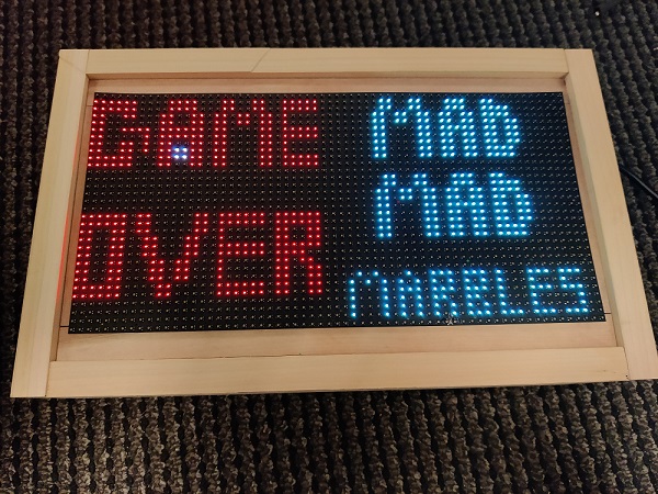
F20: Maddening Marbles
Contents
Maddening Marbles
Objectives & Introduction
Objectives
- Create smooth and natural feeling motion controls using the SJTwo's onboard accelerometer.
- Implement a collision detection system that can detect stage goals and will allow the marble to roll along walls.
Team Members & Responsibilities
- Scott LoCascio
- Game timer
- LED Matrix driver implementation
- Game graphics
- Case/housing for project
- Wiki editing
- Francesco Vescio
- Gameplay and concept
- Collision logic
- LED Matrix driver design
- Motion controls
- Wiki editing
Schedule
| Week# | Start Date | End Date | Task | Status |
|---|---|---|---|---|
| 1 |
|
|
|
|
| 2 |
|
|
|
|
| 3 |
|
|
|
|
| 4 |
|
|
|
|
| 5 |
|
|
|
|
Parts List & Cost
| Quantity | Item | cost |
|---|---|---|
| 1 | 5-Volt 20-Amp Power Supply | $20 |
| 1 | 64x32 RGB LED Matrix | $74 |
| 1 | SJTwo Microcontroller | $50 |
Design & Implementation
Hardware Design
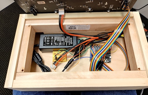
The hardware for this project consists of an SJTwo microcontroller, an LED matrix and a power supply. The microcontroller handles the game logic, drives the display, and interfaces with its on-board accelerometer to control the game.
Hardware Interface
The LED Matrix requires 13 pins to function, which are connected to 13 pins on the SJ2 board configured as GPIO output pins. All pins are active high, except for the OE pin. These pins are initialized in the led_matrix__init() function.
The display is enabled by the active low OE pin. When the display needs to be updated, it needs to be disabled and the data unlatched by resetting the LAT pin. Then, two rows of LEDs are selected by setting pins A, B, C, and D, which act as a 4-to-16 decoder. The R1, G1, and B1 pins control the LED in the upper selected row, and the R2, G2, and B2 control the LED the lower row (16 rows down). Then, the CLK and LAT pins are toggled on/off in order to load the data into the LED matrix and select the next column of LEDs. After all LEDs for a row are updated, LAT is set, OE is reset, and a delay is added to prepare for the next row. When all rows are finished being updated, the OE pin is set again to display the LEDs.
| LED Matrix Pins | SJTwo Pins | Function |
|---|---|---|
| R1 | P0.18 | Controls red color for rows 0-15 of the LED matrix |
| R2 | P0.17 | Controls red color for rows 16-31 of the LED matrix |
| G1 | P0.22 | Controls green color for rows 0-15 of the LED matrix |
| G2 | P2.9 | Controls green color for rows 16-31 of the LED matrix |
| B1 | P0.15 | Controls blue color for rows 0-15 of the LED matrix |
| B2 | P0.16 | Controls blue color for rows 16-31 of the LED matrix |
| A | P2.7 | One of four decoder inputs used to select the rows of the matrix |
| B | P2.8 | One of four decoder inputs used to select the rows of the matrix |
| C | P2.5 | One of four decoder inputs used to select the rows of the matrix |
| D | P2.6 | One of four decoder inputs used to select the rows of the matrix |
| CLK | P2.2 | Clock input used to shift bits into the display registers |
| LAT | P2.4 | Latch input used to save the state of the pins |
| OE | P2.0 | Output Enable, used to enable the display to power LEDs according to the current configuration of the display registers |
| GND(x3) | GND | Three ground pins of the display connect to a common ground on the SJTwo |
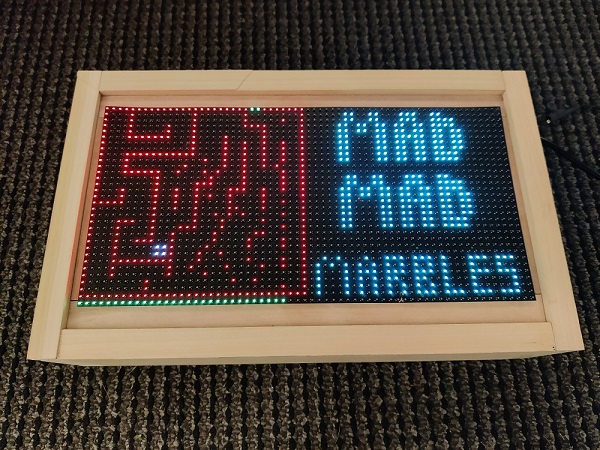
The enclosure is a wooden box designed by the team.
Software Design
The LED matrix driver, led_matrix.c, handles pin assignments, setting LEDs on and off, drawing mazes, updating the display, drawing and erasing the marble, and displaying the timer.
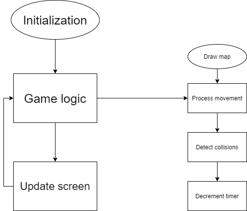
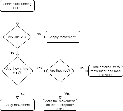
The game logic is contained in the marble.c file. The marble__init() function initializes the accelerometer, "zeroes" the marble so that the position you hold the LED board at is considered "flat," and sets the next stage to load to the title screen. The marble__handle_movement() method reads the accelerator reading, scales it to prevent choppy movement, calculates what the change in movement should be, and calls the marble__update_marble_position() function. This function checks the 12 spaces around for any obstacles that will limit its movement. If the ball will roll to the maze's goal, the next maze is loaded by a call to marble__draw_next_stage() and the marble repositioned to the starting position for that maze, which is determined by a call to marble__get_starting_coordinates(). The game timer is in the led_matrix.c file. The timer is displayed on the bottom of the board as a line of LEDs that slowly turn off. The LEDs start green, but when half of the time is remaining they turn yellow, and when a quarter of the time remains they turn red. When the timer runs out, the game over screen is displayed and the game resets back to the title screen.
FreeRTOS is used as the real-time operating system (RTOS) to manage the timing and call the various interfaces mentioned above. Two tasks are used. The highest priority task is the screen refresh task runs every 10 milliseconds to update the display based on the current state of the LED matrix buffer. The next task is called every 100 milliseconds and updates the position of the marble in the maze based on accelerometer readings and processes any interactions with the maze environment caused by the change in position.
Technical Challenges
LED Matrix Driver
The LED matrix used in this project suffered from a lack of documentation. Adafruit has a tutorial on their website that uses a Python library they developed for use with Arduino boards. With no datasheet to reference, this project had to reference previous years' projects that used the same hardware. Specifically, it wasn't initially clear how the row select worked with the A, B, C, and D bits, as well as when the LAT pin should be driven high/low to latch/unlatch the data to update the display. After some trial and error, we figured out how to properly use the LAT pin.
Motion Controls
Creating smooth feeling motion controls required some finessing. Because we planned to mount the SJTWO-C board to the back of the LED matrix but were testing the game by holding the board directly, we couldn't be sure that the controls we developed would feel smooth in the final build.
Collision Detection
Issues arose with collision detection in mazes with tricky geometry. The marble would not move in certain directions despite having clearance. Some extra logic had to be added to the cases where a marble moved towards an LED lit in one of the four adjacent corners to eliminate the movement in a direction where there was not room enough for the marble to roll to or the direction in which the magnitude of movement was the smallest.
Conclusion
This project allowed us to take the concepts learned during the embedded systems course and put them into a practical application. We had to be creative about how we designed our game logic and mindful of how we were implementing the hardware interface. It was definitely a learning experience to see all of the work and consideration that goes into creating every aspect of a product.
Our game does have a limited set of features but can be expanded upon in the future. At some point, we would like to integrate score elements, a leaderboard, and audio. We were concerned that if we tried to implement too expansive of a feature set that we may have a lot of half baked features and an unplayable game. We prioritized accomplishing the parts necessary to have a complete game from start to finish and reached our goal. Ultimately, this project was a challenging learning experience and a lot of fun.
