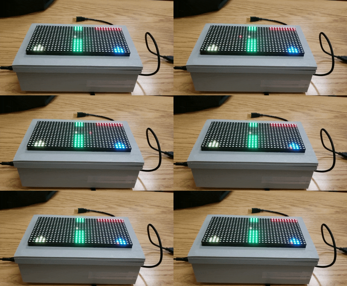
F19: Pocket tank
Contents
Pocket Tanks
Abstract
Pocket Tanks is a fast-paced and incredibly fun artillery game. It's a one versus one battle between two tanks the aim being to destroy your opponent with firepower or bury him by firing into the surrounding landscape.
The idea is to position the tank by moving it left or right and then modifying one's shooting angle and power in order to cause maximum damage to the opponent.
Objectives & Introduction
Team Members & Responsibilities
- Adithya Baskaran
- Game development, PCB design,Mp3.
- Tarun Chawla
- Game development, RGB matrix driver design.
Schedule
| Week# | Date | Task | Status |
|---|---|---|---|
| 1 | 10/1/2019 |
|
|
| 2 | 10/15/2019 |
|
|
| 3 | 10/22/2019 |
|
|
| 4 | 10/29/2019 |
|
|
| 5 | 11/5/2019 |
|
|
| 6 | 11/12/2019 |
|
|
| 7 | 11/19/2019 |
|
|
| 8 | 11/26/2019 |
|
|
| 9 | 12/3/2019 |
|
|
| 10 | 12/10/2019 |
|
|
| 11 | 12/17/2019 |
|
|
| 12 | 12/18/2019 |
|
|
Parts List & Cost
| Item# | Part | Manufacturer | Quantity | Cost($) |
|---|---|---|---|---|
| 1 | SJ Two Board | Preet | 1 | 50.00 |
| 2 | Adafruit RGB LED Matrix | Adafruit | 1 | 62.00 |
| 3 | Power Adapter | Power Supply | 1 | 7.95 |
| 4 | JLC PCB | JLC PCB | 1 | 22.00 |
| 6 | Miscellaneous (Jumper Wires, Connectors, Switches) | Excess Solution | 2.00 |
- Total Cost: $143.95
Design & Implementation
The design section can go over your hardware and software design. Organize this section using sub-sections that go over your design and implementation.
Hardware Design
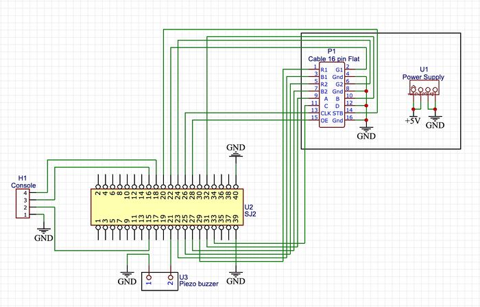
The Hardware design for Poket Tanks involves the use of two SJtwo LPC1758 microcontroller boards, 16x32 RGB LED Matrix and Active Buzzer as described below. Pin configuration information for integration with PCB and power source have been detailed.
LED Matrix
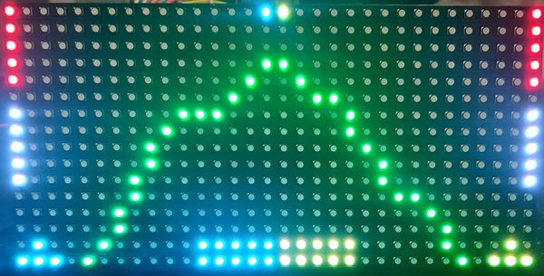
The Project uses 32x32 6mm pitch RGB LED Matrix consisting of 1024 RGB LEDs.
32 rows of LED matrix have been divided into 16 interleaved sections/strips.
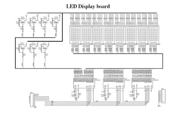
On the PCB is 12 LED driver chips. These are like 74HC595s but they have 16 outputs and they are constant current. 16 outputs * 12 chips = 192 LEDs that can be controlled at once, and 64 * 3 (R G and B) = 192. So now the design comes together. We can have 192 outputs that can control one line at a time, with each of 192 R, G and B LEDs either on or off. The LPC1758 controller selects which section to currently draw (using A, B, C and D address pins - 4 bits can have 16 values). Once the address is set, the controller clocks out 192 bits of data (24 bytes) and latches it. Then it increments the address and clocks out another 192 bits, etc until it gets to address #15, then it sets the address back to #0.
To light up an individual pixel, appropriate row value is loaded on to the address pins A,B,C & D, Clock is set out to traverse the row
and when required pixel is reached, the latch is set high to turn ON the LED.
We have used the Adaafruit GFX libaray. In this library a 3D array of size 32*32*3= 3072 bytes is used. This 3D array basically represents the whole matrix with the three RGB values. Each function in the library takes the arguments of rows and columns and just makes the corresponding byte high in the matrix. The update display function is called in a repetitive interrupt function. This function loads travesses the 3D array and selects the appropriate row and loads the row using clk pin and finally latches in the value.
Technical Specification:
Dimensions: 192mm x 96mm x 12mm (7.6" x 3.8" x 0.5")
Panel weight with IDC cables and power cable: 357.51g
5V regulated power input, 4A max (all LEDs on)
5V data logic level input
2000 mcd LEDs on 6mm pitch
1/16 scan rate
Indoor display, 150 degree visibility
Printed Circuit Board (PCB)
The PCB schematic and Layout have been designed using Eagle 9.2.2. The circuit board consists of single power supply which will be powering
- SJtwo Board (5.0V)
The Circuit uses LM7805 Voltage regulator IC from Texas Instruments to meet the power requirements. The output of voltage regulator will be typically 5V, 1.5A thus preventing excess current to SJtwo boards. 9V, 4A adapter was used to power the LED Matrix. The LED Matrix which comes with dual Molex headers. Each of the two were safely connected to LED Matrix and Circuit board to power them accordingly. The circuit design has been made robust and versatile. The voltage regulator uses decoupling capacitors placed in parallel at input and output. They bypass the AC component at the input and improve the transient response at the output. Further, a diode has been connected in shunt across the regulator to provide reverse bias protection.
Hardware Interface
Push Buttons
Three Push buttons are integrated to facilitate the movement of the tanks. The shooting angles are also mapped to these push buttons. The leftmost Push button is mapped for the left movement of the tank. The Center button is mapped for right movement of the tank. The rightmost button is meant to initiate shot selection. When the Rightmost button is selected, the movement buttons are overwritten for shot selection. The power percentage moves from 25, 50 and 75 percentage. The Left, center and right buttons handle these 25, 50 and 75 percentage shooting respectively. The pushbuttons consist of a GPIO pin and a ground pin. The GPIO pin is pulled up and the ground pin is connected to common ground. When the pushbutton is pressed, the GPIO will be grounded and pushbutton reaches logic low indicating button press.
Piezo Buzzer
Piezo Buzzer was used to give background Sound for the game. Piezo buzzer has two pins, A GPIO pin which channels PWM signals and a ground pin. Varying Frequency and Duty cycle can be used to produce sound at a different pitch. Piezo buzzer produces programmed sound at the end of the game after a player wins until a button is pressed.
Software Design
Show your software design. For example, if you are designing an MP3 Player, show the tasks that you are using, and what they are doing at a high level. Do not show the details of the code. For example, do not show exact code, but you may show psuedocode and fragments of code. Keep in mind that you are showing DESIGN of your software, not the inner workings of it.
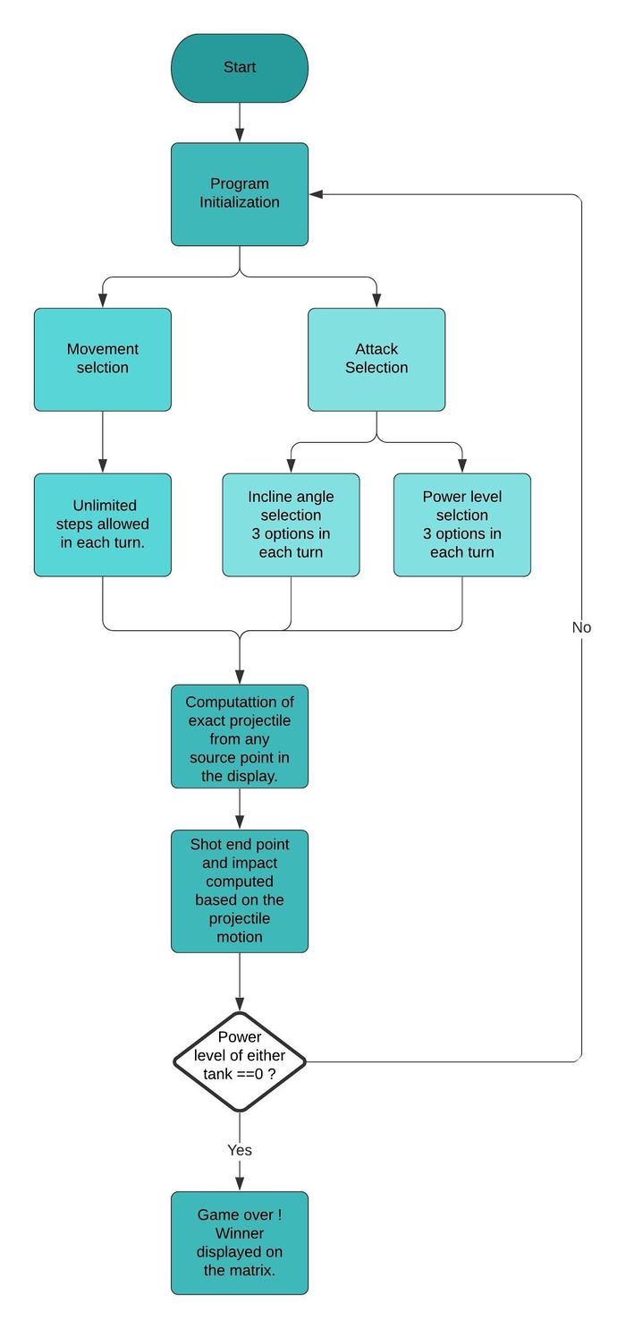
We start the game with the Program Initialization. In this, we have two options we can choose from. The options being - Movement Selection and Attack Selection. We have to choose Movement Selection to get to Attack Selection. If we choose Attack Selection first, we will not be able to move the current player's tank from one position to another. The Movement Selection helps us move from one spot to another and strategically place the tank in order to attack the opponent's tank. After we place the tank in the desired position, we choose the Attack Selection where we further have two options - Choose angles and Choose power. We have three options of angles to choose from - 23.5, 45 or 90 degrees. after we decide on the angle, we choose on the power. The power also has options - 25%, 45%, 80%. These can change according to the power the player decides to choose. The higher the power, the more the range towards the opponent's tank. The higher the power, the further the missile of the player's attack goes. This is basically the logic of the game and this goes on until one of the two players lose their armor and replenish their tanks. The winner is displayed along with the Game Over screen. Once the Game Over screen is displayed, we have a restart option to choose. If this option is chosen, the game restarts from the Program Initialization where we choose the Movement Selection option and continue the above explained method.
Implementation
This section includes implementation, but again, not the details, just the high level. For example, you can list the steps it takes to communicate over a sensor, or the steps needed to write a page of memory onto SPI Flash. You can include sub-sections for each of your component implementation.
Piezo Task
Piezo task handles acquiring frequency values for each note and setting the desired time duration on the PWM channel to play the note. Each note should be played for a specific duration depending on the song speed. The note will be played until duration using inbuilt delay functions.
static void piezo__task(void *params) {
  const gpio_s piezo = gpio parameter;
  while (true) {
    for (did iteration reached 203 notes?) {
      int wait = The duration each note should be played for based on song speed;
      initialize pwm1 with single edge; // frequency
      Set pwm1 duty cycle for desired value;
      wait untill 'wait' duration to play the note;
    }
  }
}
Draw base Task
Draw base task draws the necessary graphics that represent the game. It draws the background blue sky, divider to represent the limit of movement, Two tanks to represent Player1 and Player2 and health bar for each of the players.
    while(1){
       draw the bluesky background;
       draw the divider;
       Draw tank for the player1;   // tank 1
       Draw tank for player2; // tank 2
       Draw the health bar for player 1;
       Draw the health bar for player 2;
     }
Shoot Task
Task handles shooting selection from players. Displays 3 possible options to be selected to shoot. After shot has been selected, prompts a screen to choose a power level for the shot to be made. Once the shot is fired and hits the opponent player, a feature appears in the path of shot which reduces the health of the player if he shoots in the same direction.
while (true) {
              wait till all LED shift registers are updated and report the button press;
              if (left button is pressed) {
                Clear shooting oprtion and display power option;
                delay till buffers are updated and button is pressed;
                Choose power option at 25% at power 1 and shoot;
                Delay till buffers are updated;
                if (player 2 health is less than 7) {
                  shot has been registered and feature appears at the path of shot;
                }
                break;
              } else if (center button is pressed) {
                Clear shooting oprtion and display power option);
                delay till buffers are updated and button is pressed;
                Choose power option at 25% at power 2 and shoot;
                Delay till buffers are updated;
                if (player 2 health is less than 7) {
                  shot has been registered and feature appears at the path of shot;
                }
                break;
              } else if (right button i.e. select  button is pressed) {
                squarep1(8, 0);
                 delay till buffers are updated and button is pressed;
                Choose power option at 25% at power 3 and shoot;
                Delay till buffers are updated;
                if (player 2 health is less than 7) {
                  shot has been registered and feature appears at the path of shot;
                }
                break;
              } else {
                The power selection button is displayed again as a reminder;
              }
            }
            break;

          }
Health Task
The health of the individual players are constantly checked and updated using respective tasks.
if (health of player 2 is <= 0) {
      Player 1 is the winner;
      make piezo flag to true to invoke piezo sound;
      while (true) {
        wait till the buffers are updated and check if any button is pressed;
        if (select button is pressed) {
          Restart the game; //restart
        }
      }
    }
    if (health of player 1 is <= 0) {
      Player 2 is the winner;
      make piezo flag to true to invoke piezo sound;
      while (true) {
        wait till the buffers are updated and check if any button is pressed;
        if (select button is pressed) {
          Restart the game; //restart
        }
      }
    }
Pushbutton Task
This can be given for multiple buttons and as individual tasks to get respective values.
static void button_task(void *params) {
  Transfer parameter to GPIO;
  while (true) {
    Check for GPIO value {
      Set button value;
    } else {
      Set button value;
    }
   Give a task delay;
  }
}
Testing & Technical Challenges
- Non-availability of datasheet for ADAFRUIT 16x32 RGB LED Matrix was a major challenge. This made the understanding of pin configuration details difficult. Subsequently, we extracted ADAFRUIT GFX library and created an interface class to make it compatible with our project requirements.
- It was hard to determine the refresh rate for LED Matrix. Low refresh rate would cause display to flicker and a high refresh rate would slow down the display update rate thereby causing overhead. Through trial and error, we came up with a value of 500us for interrupt which was an ideal refresh rate value.
- It was great challenge to implement the pause feature in the game. We had to capture the real time movement of the attacks when the user hit pause and resume the game from same position. The push button switch on joystick was used to pause and game would resume with input direction.
- Starting the game with initial tank position was challenging due to the designed algorithm. This was overcome by calculating the tank location before start of the game by hard-coding the default direction on game start.
- Approach to design a PCB to meet the project requirements was complex. We had to redesign the circuit schematic and layout thrice to ensure that it was robust. Moreover, We had to import libraries from Sparkfun and adafruit for various components and also make sure that the same were available with Digikey.
- Mapping the trajectories of the attack route took some time since it was changing with respect to the power value selected.
- The Song Notes to be converted into frequencies was harder than expected and the delay between the notes took a toll to match.
Bug/issue name
- The LED Matrix display was constantly flickering and we couldn't narrow down the reason behind it. Once all the circuit connections were properly made, this issue was resolved.
- The top-leftmost LED blinks whenever game restarts. This was bug which couldn't be resolved.
Conclusion
The project was a success both in terms of output and learnings. We were able to design the pocket tanks game which has been controlled via a handheld joystick using push buttons. It gave an exposure of working drivers for 16x32 RGB LED Matrix, push buttons and active buzzers. It helped us utilize the knowledge of FreeRTOS and GPIO driver gained through the CMPE-244 class.
Working as a team and having brainstorming sessions helped us in overcoming a lot bugs which we encountered during game design. Furthermore, it helped in expediting the integration, testing and debugging of the project days before final demonstration. On the whole, we had a wonderful experience of working in a team and developing a complete product using professional tools and techniques.
In addition, post completion of the project we have understood the methodology behind scheduling multiple tasks in order to ensure real time operation and deterministic scheduler behavior.
Project Video
Project Source Code
References
Acknowledgement
We would like to sincerely thank Professor Preetpal Kang for his allround guidance, feedback and support. His classroom lectures were significant in imparting knowledge on embedded systems. Further, we would like to thank ISA team for their advice. Additionally, I would like to extend my gratitude to the members of the SCE lab at SJSU including Neeraj, Daniel and Tiago for helping me out with 3D printing the casing for the game console.
References Used
https://cdn-learn.adafruit.com/downloads/pdf/32x16-32x32-rgb-led-matrix.pdf?timestamp=1543806512/
Appendix
You can list the references you used.
