F16: Wireless Tilt Controlled Camera Arm
Contents
Wireless Tilt Controlled Camera Arm
Abstract
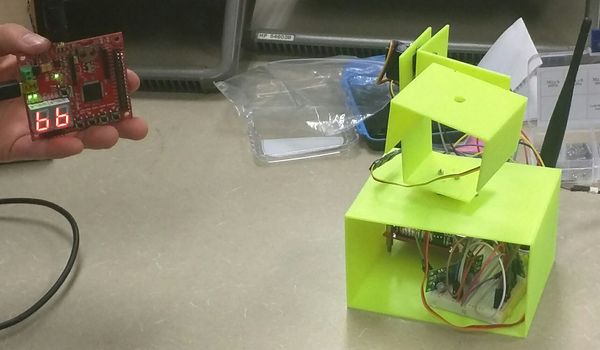
For this camera system, the camera moves according to the tilt of the wireless controller, which will be one of the two SJOne boards. The camera is mounted on a mechanical arm that is connected to the second SJOne board. The camera's movement speed is set. However, the camera's direction is determined by the angle in which the controller is tilted. The controller's tilt will be tracked using the attached SJOne board’s accelerometer and used in the movement of the camera arm. Similar to the movement of the human eye, the camera arm in this camera system is able to move nearly 180 degrees in all directions in forward vision, allowing for a wide range of different camera angles. The camera can look at an angle in any direction such as left, right, up, and down. If there is an error, the user can reset the camera arm motion controller to reset the camera back to the center position so that the camera is facing the correct orientation. Data is transferred through wireless communication between the two SJOne boards.
Objectives & Introduction
The objective for this project was to learn how to use motors and to use them to implement a project. Here, a camera arm was designed in order to take acceleration sensor data from one board and and through wireless communication, receive information on how to move the arms with respect to how the control board would move. The following objectives were set for the project:
1. Design an arm in CAD software to hold all the motors that will perform all the movements.
2. Research the proper hardware needed for the expectations for the project, which would be high precision motors that are capable of fine movement.
3. Write software to control motors and to establish wireless communication across 2 devices.
Team Members & Responsibilities
- Kevin Lai
- Acceleration Sensor and Wireless Communication Software Developer
- Document Writer
- Alex Reyna
- Arm and Track Designer, and Motor Driving Software Developer
- Document Writer
Schedule
| Week# | Start Date | End Date | Task | Status | Actual Completion Date |
|---|---|---|---|---|---|
| 1 | 10/8 | 10/14 | Write Project Proposal | Completed | 10/14 |
| 2 | 10/14 | 10/21 | Finalize Project Design | Completed | 10/21 |
| 3 | 10/21 | 10/28 | Research and Determine Necessary Components | Completed | 10/28 |
| 4 | 10/28 | 11/11 | Purchase Parts | Completed | 11/15 |
| 5 | 11/11 | 11/18 | Generate Schematics and Begin Prototyping | Completed | 11/18 |
| 6 | 11/18 | 11/25 | Program First Microcontroller to Act as Wireless Remote Controller of Camera Arm | Completed | 11/23 |
| 7 | 11/25 | 12/2 | Create Movable Camera Arm | Completed | 12/9 |
| 8 | 12/2 | 12/9 | Program Second Microcontroller to Interface with the Camera Arm | Completed | 12/16 |
| 9 | 12/9 | 12/16 | Perform Final Tests, Generate Final Report, and Prepare for Demo | Completed | 12/19 |
Parts List & Cost
A part list for our project.
| Part Name | Model Number | Quantity | Cost (Total) | Notes |
|---|---|---|---|---|
| Microcontroller | SJOne Board | 2 | $160 | One for Main Wireless Controller and One for Camera Motion Controller |
| 2.4GHz 6dBi Indoor Omni-directional Antenna | Antenna | 2 | $9 | Used for wireless communications between the boards |
| Osoyoo Micro Servo Motor | SG90 | 10 | $20 | Used for the motor control for the arm |
| High Torque Metal Gear Feather Servo Motor | HS-5065MG | 2 | $54 | Used for the motor control for the arm |
| 5V Step-Up/Step-Down Voltage Regulator | S18V20F5 | 1 | $15 | Used for regulating power to the SJOne Board |
| 6V Step-Up/Step-Down Voltage Regulator | S18V20F6 | 1 | $15 | Used for regulating power to the motors |
| 3D Printed Arm | SCE | 1 | $0 | 3D printed at SJSU's SCE Club Room, free of charge with club membership |
Design & Implementation
The Wireless Tilt Control Camera Arm design was broken up across two boards, both hardware and software. One board was going to be used to get data from the on-board acceleration sensor, interpret it and send it wireless over to a second board to that would receive the information transmitted and move the motors accordingly.
Hardware Design
Motor Control
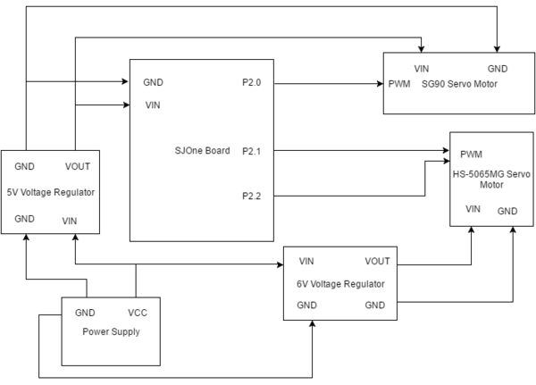
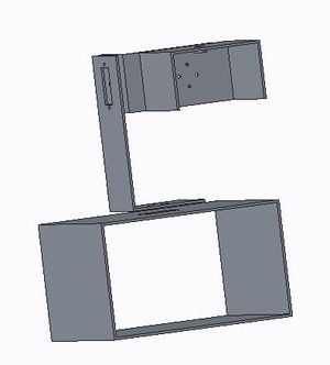
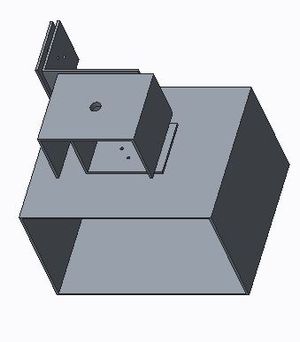
The hardware design mainly focused on the motor control board. No additional hardware was implemented to the board that was sending the acceleration sensor data. Three motors were used in the arm design. 2 high precision servos, the HS 5065MG micro servos, were chosen to be used in the hardware design because of their ability to have fine control and movement. They are not typical servos that moved in a manner that required a certain amount of pulse to trigger or needing a certain length to the duty cycle. Rather, the servo rotates based on the duration of the pulse. The motor had a workable range of 750 - 2250 microseconds. The servo had a workable range of of 120 degrees. These were the more expensive motors and had metal gears. The third motor was the Osoyoo SG90 micro servo, which had a duty cycle of 50 hz, or 20 ms. It required a pulse of 1-2ms to rotate the motor 90 degrees, either to the left or to the right. These motors were much simpler and had plastic gears. These were not able to provide fine control. In order to power all the devices, two voltage regulators were purchased. A 5V Step Up/Step Down voltage regulator from Pololu was purchased to power the SG90 servo and the SJOne board. A 6V Step Up/Step Down voltage regulator from Pololu was used to power the precision servos. The 6 volts to the motors guaranteed highest efficiency and precision. All the hardware was housed in arm design in CAD tools. The design can be seen in Figure 2 and Figure 3. The schematic and hardware layout can be seen in Figure 1.
Hardware Interface
The motors received pulse width modulation (PWM) signals from the 2.0-2.4 GPIO pins boards on the SJ One board. All devices had to share a common ground port to work efficiently. The onboard PWM API was used to control the motors. They had to be slightly tuned in that inputting a value of 50 into the initialization of the PWM . Setting the value of 4 in turn actually generated a duty cycle of 20 ms. This was verified using an oscilloscope. The percentage of the duty cycle was calculated to measure to correct duration of pulse needed to move the motors.
Software Design
Board-to-Board Wireless Communication
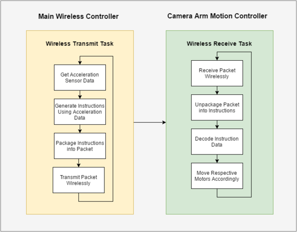
The board-to-board wireless communication utilizes Nordic Wireless on the SJOne board. Two additional tasks were created to perform the intended operations needed in this project: one task for wireless data transmission and one task for wireless data reception. The main wireless controller performs the task that transmits data while the camera motion controller performs the task that receives data. The transmit task first interprets and uses the acceleration data captured by the SJOne board's acceleration sensor to generate the appropriate instructions to send to the camera motion controller. Then, after the instructions have been generated, the transmit task packages the instructions into a packet and sends the packet wirelessly to the other board. The receive task receives the wireless packet and unpackages the packet to obtain the instruction data. Then, the receive task uses the instruction data to control the movement of the motors. Figure 4 describes the general software design of the project.
Implementation
Board-to-Board Wireless Communication
The wireless communication used the wireless API to perform the formation of a wireless packet and the wireless transmission of the packet. Initialization of the SJOne boards' wireless features was mostly handled by the default wireless task. For wireless communication, the wireless channel number and the air data rate used by both boards must be the same. The two boards used in this project each had their own wireless node address, which was used to uniquely identify each of the boards during the wireless communication. Both tasks were set to HIGH priority to ensure that they were running all of the time. Figure 5 describes an more in-depth view and explanation of the functionality and process of the two tasks used in this project.
Testing & Technical Challenges
Wireless Stability
Issue
Initially, as we were testing the board-to-board wireless communication, many packets would often be lost during the transmission.
Solution
We determined that the cause of the issue was the Nordic Wireless's limited wireless range. As such, in order to resolve this issue, we reduced the air kbps rate down to provide a more stable signal in a larger wireless range.
Getting Motors to Work Properly
Issue
Motors were acting sporadically and not as expected.
Solution
By connecting every component in the design to common ground, we were able to resolve this issue.
Conclusion
This project was a success because we completed all of our intended objectives. The two boards were able to wirelessly communicate with each other and were able to receive and send packets of data. The camera arm was able to move according to the instruction data sent wirelessly from the main wireless controller. This project increased our knowledge in both hardware and software designs. We learned a lot about the wireless API and how two boards can communicate wirelessly with each other by sending and receiving packets of information. We also learned a lot about motors and how to use them in a hardware design. Overall, we learned how to design a mechanical arm and control the mechanical arm wirelessly.
The project was done as successful as we wanted. We started with the idea of control a camera over wireless communication. Software was going to be created to gather information from an acceleration sensor, interpret the data and transmit relevant information to a board that had motors that controlled a 3D printed arm. Much of the stuff was new, as in using motors and using PWM, understanding and implementing wireless communication over Nordic mesh network. This led to some drawbacks in understanding how to interfacing items into the projects. The project was a great learning experiencing and exposed us to new and fun concepts.
Project Video
Project Source Code
References
Acknowledgement
We'd like to thank Preet and Dr. Ozemek for their commitment to everyone and the limitless effort that they provide for San Jose State.
